
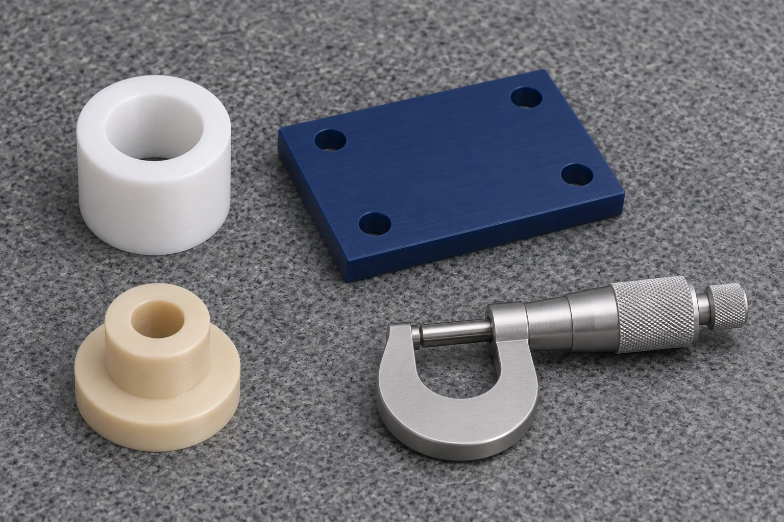
Measuring machined plastic parts requires a defined measurement state, suitable contact force and consistent support. A finer display cannot compensate for deforming the component. You should agree the inspection method before ordering tight tolerances, especially when supplier and receiving measurements must match.
Define The Dimension You Actually Need
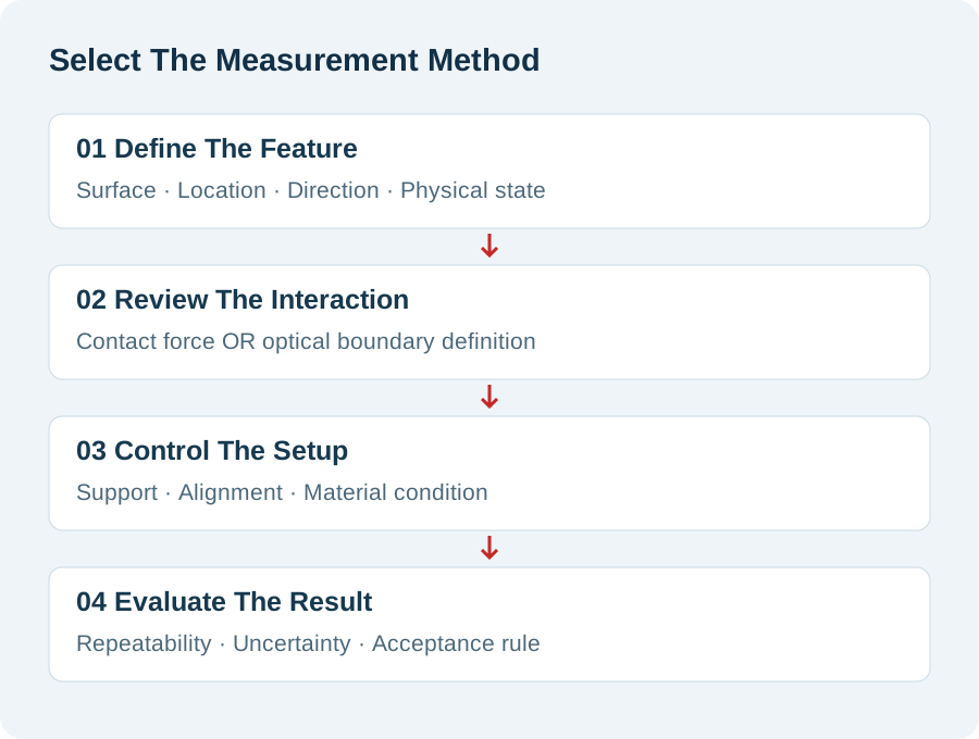
You should define the measured feature and its physical state before choosing an instrument.
A diameter on a flexible bushing can mean several different things. You might need its free diameter, its installed bore or its functional clearance. Those results answer different engineering questions, even when each report uses the same unit.
Start with the drawing revision and functional relationship. Identify the surface, measurement direction and relevant datum. State whether the component is free, supported or restrained. If installed inspection matters, define the mating condition separately.
For purchased components, make the acceptance state visible on the inspection plan. Do not expect receiving inspectors to reconstruct it from the assembly model. A supplier can measure the correct nominal feature in a different state and reach a different result.
Separate Resolution From Measurement Confidence
You should judge the complete measurement process rather than relying on the smallest displayed increment.
Resolution describes the instrument's display increment or discrimination. It does not establish the uncertainty of your actual result. Setup, alignment, workpiece behavior and environment can contribute additional variation.
The National Physical Laboratory's uncertainty guide explains contributions from instruments, workpieces, environments and operators. It also distinguishes uncertainty from measurement error. Use that distinction when evaluating a proposed inspection method.
Ask how the method's capability relates to your tolerance and acceptance decision. Avoid inventing a universal instrument-to-tolerance ratio for every feature. Your quality team should evaluate the actual measurement process and applicable customer requirements.
A calibration record remains useful, but its scope matters. It does not independently validate your fixture, edge detection or handling sequence. Those belong in the application-specific method review.
Control Contact Force And Contact Geometry
You should evaluate whether the measuring contact changes the dimension you are trying to observe.
A small contact can indent a surface. A larger contact may distribute load differently, while interacting with local curvature or nearby edges. Lower force can reduce deformation in suitable setups, but it cannot resolve every support or contact problem.
Mitutoyo's low-force measurement guidance discusses delicate workpieces and contact-tip selection. Its examples support evaluating force and indentation together. They do not provide a universal force setting for every polymer component.
Use representative parts when selecting the contact arrangement. Compare repeated results while controlling position and support. If readings change when you tighten the instrument, investigate deformation before treating the difference as manufacturing variation.
Document the selected force-control mechanism or operating technique. Naming the instrument alone may leave substantial operator discretion. Your receiving team needs enough detail to reproduce the intended contact condition.
Support The Part Without Redefining Its Shape
You should support the component consistently while preserving the measurement state required by the drawing.
A thin plate can move when supports change. A ring can respond differently when held across its diameter. A component resting on debris may tilt before the probe touches it.
Define support locations and orientation for sensitive features. Avoid adding clamps merely to make readings stable. Restraint can create repeatable results for a shape that disappears when you release the part.
If your requirement concerns an assembled condition, a controlled fixture may be appropriate. Identify the locating surfaces, restraint sequence and relevant installation conditions. Keep this method separate from any free-state dimensional check.
For additional discussion of shape-sensitive measurements, see flatness in machined plastic parts. Apply the same discipline to thickness, parallelism and hole relationships when their results depend on support.
Match The Method To The Feature
You should select the measurement principle according to access, deformation risk and the feature's functional definition.
The following table compares questions to resolve during planning. It does not rank every instrument by accuracy. Different instruments can be suitable when the complete methods are demonstrated.
| Feature | Candidate Method | Main Setup Question | Acceptance Concern |
|---|---|---|---|
| External thickness | Controlled-force contact measurement | Where are the support and contact points? | Local indentation or bending |
| Bushing bore | Suitable bore measurement or agreed gauging | Which depths and directions represent the requirement? | Taper, ovality and contact effects |
| Hole position | Coordinate measurement | How are datums established? | Alignment and sampling strategy |
| Thin profile | Optical or other evaluated method | How is the visible edge defined? | Lighting, focus and edge selection |
| Installed fit | Defined mating fixture or functional check | What installation state is reproduced? | Confusing fit with independent dimensions |
Your quality and inspection review should connect these choices to the actual drawing. An equipment list alone cannot establish how a difficult feature will be accepted.
Measure Bores At Agreed Locations And Directions
You should define where a bore is measured before comparing diameter results across organizations.
One reading near an entrance does not describe every location along a bore. A chamfer, burr or local distortion can influence contact. Likewise, a single direction may miss a change observed after rotating the measurement orientation.
Define the relevant measurement depths and directions for your feature. Choose them according to function and the drawing requirement. Avoid turning an arbitrary sampling pattern into a universal acceptance rule.
Mitutoyo's caliper guidance identifies measuring force and inside-jaw geometry as potential error sources. Check whether the instrument's contact geometry suits the bore size and access. A convenient caliper reading may need a more suitable method for final acceptance.
If a mating shaft passes, record what that functional check demonstrates. It does not automatically establish bore geometry or clearance throughout the working length. Keep dimensional and functional evidence identifiable.
Treat Optical Measurement As A Different Method
You should evaluate optical edge definition instead of assuming noncontact measurement removes every source of uncertainty.
Optical methods can avoid a mechanical probe pressing on the inspected edge. However, lighting, focus, transparency and surface appearance can affect which boundary the system identifies. A chamfered edge can also produce more than one visible transition.
Agree which edge represents the drawing dimension. Retain setup information for lighting and image processing where it affects the result. Use representative components rather than validating only an easy reference shape.
For transparent or reflective components, discuss access and contrast during manufacturing planning. Avoid applying an improvised coating without approval. That treatment could affect the surface, dimensions or downstream use.
Compare optical and contact results against the same feature definition. A difference may reflect how each method identifies the boundary. Investigate the method before assigning the entire difference to the component.
Record Temperature And Material Condition
You should compare results only after checking whether the component conditions are meaningfully comparable.
A component moved from machining, washing or transport may be changing condition. Holding it repeatedly can also change its temperature. Define a practical handling sequence for measurements sensitive to these effects.
Your inspection plan should identify the agreed environment and preparation state. Record relevant temperature information when required by the method. Avoid assuming that the room temperature immediately represents every part's temperature.
Moisture-sensitive materials add another condition to review. A dry incoming sample and a conditioned production component may not represent the same state. Our nylon moisture absorption guide explains why the conditioning basis belongs in the specification.
Do not invent one waiting period for every geometry and polymer. Agree the conditioning method using the material, component size and application. Record exceptions when urgent inspection occurs before the agreed state is reached.
Check Repeatability Before Interpreting Small Differences
You should investigate the method's variation before interpreting small reading changes as a process trend.
Begin with repeated measurements using the same defined setup. Then evaluate changes introduced by repositioning the part. Where multiple inspectors use the method, include representative operators in the review.
Keep the sequence structured. Change one relevant setup element at a time when diagnosing a discrepancy. Otherwise, temperature, alignment and force changes can become difficult to distinguish.
Before comparing organizations, exchange one representative sample with its method record. Confirm that both teams inspect the same locations. Record the sample identification and transport history. This helps you separate setup differences from differences between production parts.
Record the raw results instead of retaining only a preferred average. A wide spread may reveal an unstable contact or support arrangement. Averaging cannot explain away a method that measures different physical states.
Your quality team should decide whether a formal measurement-system study is needed. Its design should reflect production use and customer requirements. This article does not prescribe a universal statistical acceptance threshold.
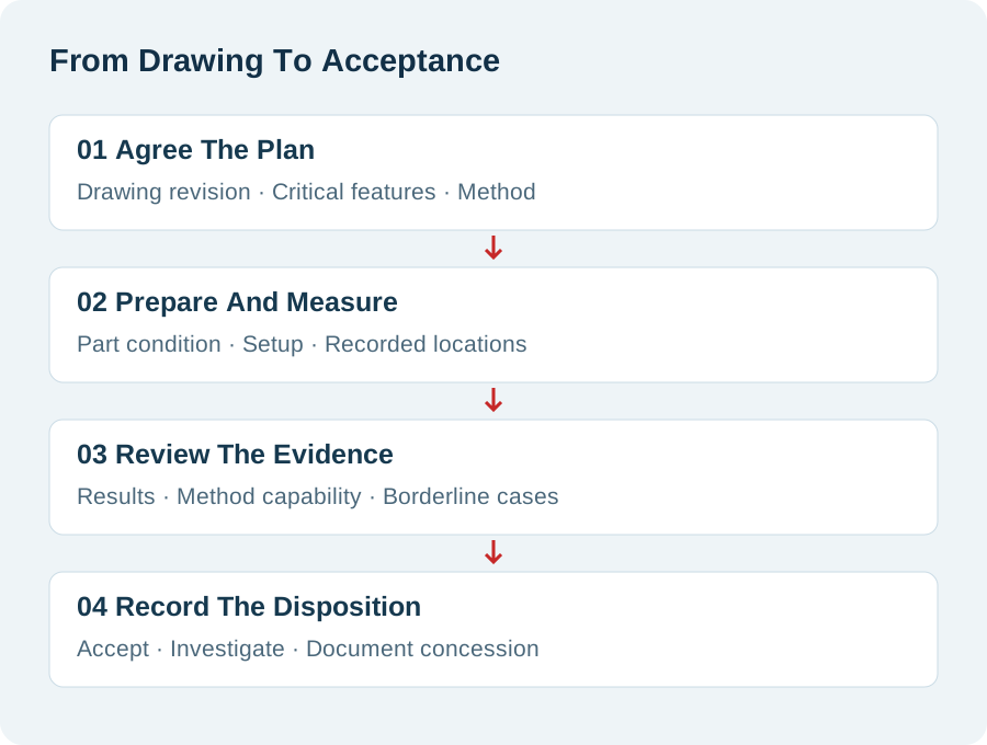
Agree How Borderline Results Will Be Decided
You should define the conformity decision before an inspection result approaches a tolerance boundary.
A number close to a limit can create disagreement when the measurement process has unresolved uncertainty. More decimal places do not settle that question. Agree the applicable decision rule with the responsible quality parties.
Specify who reviews borderline results and what additional evidence can be requested. Define whether a repeat measurement must reproduce the original setup. A different instrument should not silently introduce a different feature definition.
Keep deviations and concessions separate from ordinary acceptance. If an engineering concession permits use, identify the affected batch and scope. Do not rewrite the inspection result to make the disposition appear routine.
For a broader approval framework, see first article inspection for plastic parts. The measurement method should remain linked to the approved drawing and sample configuration.
Build A Report That Another Inspector Can Use
You should retain enough method information for a second team to understand the result and reproduce its basis.
A result table needs more than nominal dimensions and pass marks. For sensitive features, connect the reported value to the measurement location and state. Record the relevant method revision when the process changes.
| Report Field | What To Record | Why You Need It |
|---|---|---|
| Part identity | Part number, batch and drawing revision | Prevents configuration mix-ups |
| Feature identity | Drawing reference and measurement location | Connects the result to the requirement |
| Physical state | Free, supported or installed | Makes comparisons meaningful |
| Method setup | Instrument, contact and support details | Exposes important setup differences |
| Conditions | Relevant preparation and environment | Supports comparison across inspections |
| Disposition | Result and agreed acceptance basis | Separates measurement from engineering release |
Retain photographs or fixture sketches when they clarify the setup. These records should show the relevant arrangement without implying unsupported accuracy. A clear method record can reduce repeated investigations during future deliveries.
Compare Inspection Costs Against Functional Risk
You should concentrate inspection effort on the features whose uncertainty could affect assembly, operation or acceptance.
A difficult tolerance can require additional setup development, fixtures or measurement time. Broadly tightening every dimension may add effort without improving function. Identify critical relationships before requesting a detailed quote.
Discuss in-process checks separately from final acceptance. A production check may guide machining without providing the entire delivery evidence package. Agree which records accompany each batch and which remain available on request.
Ask TOPS to confirm the proposed method and available evidence for your component. The website presents machining and inspection services, but this article does not verify a specific instrument inventory. Special measurement arrangements require order-specific confirmation.
Include quantity and repeat demand when discussing the plan. A method suitable for a prototype may need different handling for routine batches. Changes should preserve the accepted measurement basis rather than merely accelerate inspection.
Measuring Machined Plastic Parts FAQ
You should resolve these common method questions before exchanging acceptance reports.
Can I Use An Ordinary Caliper?
Possibly, depending on the feature and requirement. Evaluate force, contact geometry and method capability before using it for final acceptance.
Does A Ratchet Eliminate Deformation?
No. A force-control feature can improve consistency, but the applied force can still affect the component. Review the complete setup.
Is Optical Measurement Always Better?
No. It avoids mechanical contact at the observed feature, but edge definition and imaging conditions still require evaluation.
Why Do Supplier And Receiving Results Differ?
Check feature definition, support, force, conditions and alignment first. Different methods can produce different results without identifying the underlying cause.
Should I Measure A Bushing Before Installation?
Measure it in the state required by your specification. Installed bore acceptance and free-state dimensions may require separate checks.
Can Calibration Replace A Method Study?
No. Calibration addresses the instrument within its stated scope. Your fixture, workpiece response and operating method need separate consideration.
Should I Average Every Reading?
No. First understand why readings differ. Averaging does not correct inconsistent locations, changing conditions or a deformed component.
What Should I Send For An Inspection Review?
Send the drawing, grade, quantities and functional requirements. Include the measurement state, disputed results and any required acceptance rules.
Request A Measurement Plan With Your Quote
You can reduce inspection disputes by defining the feature, state and method before production. Control force and support where they matter. Keep measurement evidence separate from concessions and installed performance checks.
Contact us with your drawing, material grade, batch quantities and critical measurement requirements. Include existing method details when you need supplier and receiving results to correlate.