
Specify flatness in machined plastic parts by the functional surface, tolerance and agreed measurement state. Distinguish surface form from thickness and parallelism. Your inspection plan should address support, contact force, temperature and surface coverage. Otherwise, two reasonable-looking measurements can answer different questions.
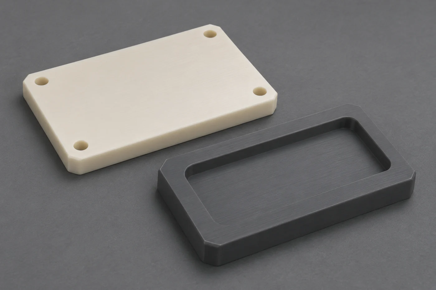
What Does Flatness Control On Your Plastic Part?
Surface flatness controls the form of an identified surface, rather than its orientation to another feature.
Imagine two parallel planes enclosing the controlled surface. Their permitted separation defines the specified flatness zone. This article concerns surface flatness, not every possible drawing application of a flatness control.
KEYENCE’s flatness measurement explanation describes that enclosing-plane concept and distinguishes flatness from parallelism. Use the governing drawing convention when applying the requirement. Have your design owner resolve ambiguous symbols or notes before quotation.
Your part may need flatness for sealing, mounting, sliding or locating another component. Name the actual surface and its function. A vague request for a “flat part” leaves the supplier guessing about both scope and acceptance.
How Does Flatness Differ From Thickness And Parallelism?
Flatness, thickness and parallelism answer different questions about your component’s geometry.
A plate can have consistent thickness while both broad faces curve together. It can also have a flat upper face that is tilted relative to the opposite face. Neither condition is fully described by a thickness measurement alone.
Parallelism introduces a relationship to a specified datum. Surface flatness does not establish that orientation relationship. If your assembly needs both, your drawing should express both requirements correctly.
Do not ask a supplier to infer parallelism from the word flatness. Explain which surface locates the part in service. Then review the relevant drawing controls with your quality and design teams.
| Requirement | Main Question | What You Must Identify |
|---|---|---|
| Surface flatness | How much does this surface depart from a plane? | Controlled surface and permitted form variation |
| Thickness | What is the separation between opposing surfaces? | Size requirement and applicable measurement locations |
| Parallelism | How is a feature oriented relative to a datum? | Controlled feature and datum relationship |
| Surface finish | What texture exists on the surface? | Required texture characteristic and evaluation method |
| Assembled seating | How does the part behave when installed? | Mounting condition and functional acceptance procedure |
A smooth-looking finish does not establish flatness. Likewise, a flatness report does not prove a seal will work. Keep geometry, texture and application testing as related but separate requirements.
Which Measurement State Represents Your Requirement?
Your measurement state should reflect the condition that the drawing and functional requirement actually specify.
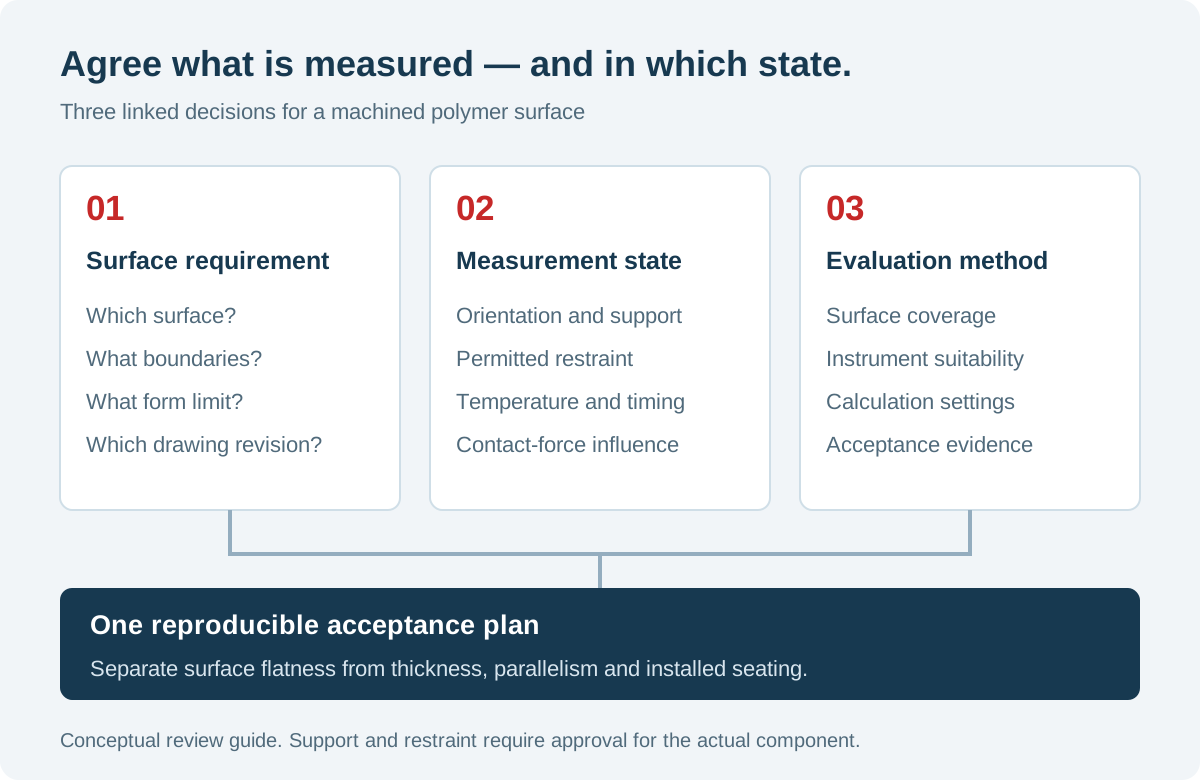
Distinguish a released component, a supported component and a restrained assembly. Every physical measurement needs some arrangement, but support must not silently become forced flattening. Document what may contact the part and how.
For a flexible cover, fastening it to a rigid fixture can change its shape. That may represent an agreed assembled evaluation. It does not automatically establish the condition of the released part.
Avoid calling a loosely supported arrangement completely unconstrained without qualification. Gravity, contact locations and orientation still matter. Describe the actual setup instead of relying on an informal label that different inspectors may interpret differently.
Your drawing owner should approve any special restraint condition. Keep that condition visible in the purchase and inspection records. Do not allow the supplier and buyer to evaluate different states unknowingly.
Why Do Material And Temperature Matter?
Polymer response to load and temperature can influence the geometry that your measurement system observes.
The Mitsubishi Chemical Group machinist’s toolkit explains differences between plastics and metals, including elasticity and thermal behavior. Those differences make measurement-state planning important. They do not establish a universal flatness capability for custom parts.
Identify the exact grade and relevant stock product. A family label alone does not describe all dimensional behavior. Consider moisture conditioning where your chosen material requires it.
Specify a suitable reference condition and any agreed stabilization procedure. Record relevant temperature differences between the part and measurement environment. Avoid measuring immediately after machining merely because the surface feels cool.
Use the thermal expansion guide when coordinating inspection and operating conditions. Your dimensional report should represent a defined state. It should not depend on undocumented handling or storage differences.
How Can Your Geometry Complicate Flatness?
Thin sections, asymmetric material removal and interrupted surfaces can complicate manufacturing and inspection of a flatness requirement.
A broad plate with deep pockets differs from a solid block with similar outside dimensions. Narrow lands and openings change support possibilities. They can also limit where an instrument can collect useful surface data.
Mark whether the controlled area includes separate lands, borders or the whole nominated surface. Do not create an informal combined-surface requirement through a vague email. Have the drawing define the intended control correctly.
The plastic pocket design guide helps identify access and remaining-wall questions. Discuss those features before tightening every tolerance. Geometry changes can sometimes improve function more directly than demanding a smaller inspection number.
What Should You Discuss About The Machining Process?
Discuss how the supplier will preserve the required released geometry while machining and inspecting your critical surface.
Ask about workholding assumptions, material removal and finishing order where they affect acceptance. A broad surface held flat during cutting may behave differently after release. Your requirements should address the result, not only the machine setup.
Do not prescribe annealing automatically for every polymer and geometry. Its need and procedure require material-specific review. If an additional process is proposed, agree its scope and subsequent inspection.
The plastic machining warpage guide covers broader movement causes. Here, connect that discussion to a specific surface and acceptance method. Ask which manufacturing decisions require your approval before production begins.
How Should You Control Support And Contact Force?
Your support and probing arrangements should hold the part for measurement without unintentionally redefining its shape.
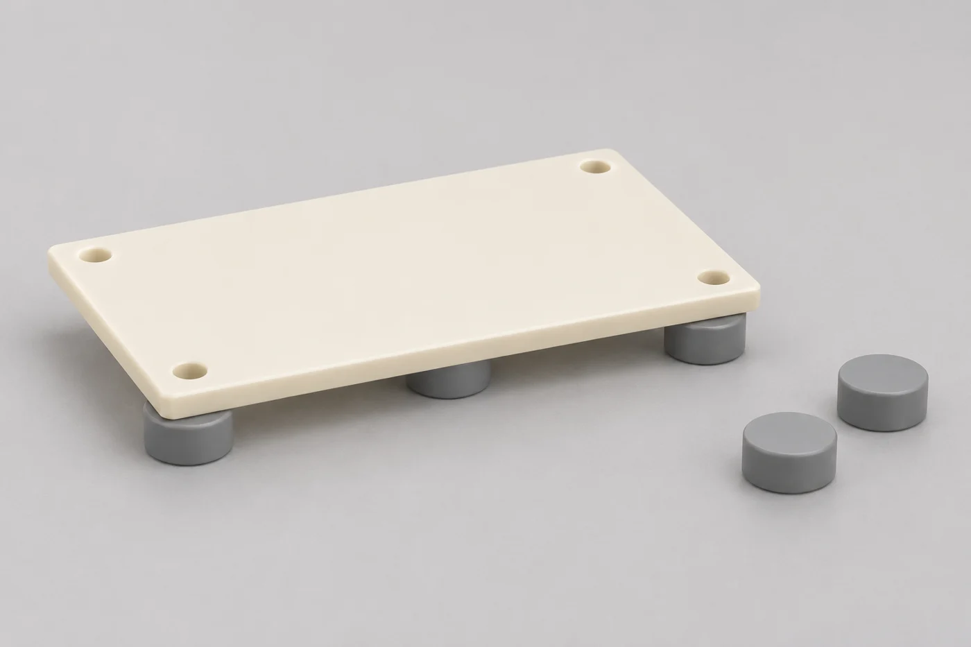
Agree contact locations, orientation and permitted restraint with the responsible metrology team. A support arrangement suitable for one geometry may distort another. Do not assume that a familiar three-point layout is correct for every flexible plate.
The support illustration shows one conceptual arrangement, not a validated fixture or universal inspection method. Pad size, spacing and loading remain application-specific. You need an approved setup for the actual drawing.
Contact measurement can also apply force to the surface. Ask whether probe force, tip geometry and part compliance could affect the result. Record the relevant settings and method limitations when they matter.
A part that rocks on a table needs investigation, but rocking alone is not a complete flatness evaluation. Local debris or edge damage can contribute. Clean and inspect the contact areas before drawing conclusions.
How Much Surface Should Your Method Measure?
Your measurement plan needs enough relevant surface coverage to detect the form errors that could affect acceptance.
A few selected points describe those points. They do not reveal every local high spot, hollow or narrow land. Agree sampling locations and coverage with the drawing owner and measurement specialist.
Choose locations around critical functional areas, rather than only where access is easy. Consider interrupted surfaces and edges explicitly. Keep excluded regions documented so the report does not imply coverage that never occurred.
Mitutoyo’s surface-plate accuracy and calibration discussion distinguishes overall flatness from local variation in surface plates. That source concerns reference equipment, not your polymer component’s acceptance recipe. It illustrates why a measurement’s scope must be understood.
Which Measurement Method Should You Select?
Select a method that can evaluate your surface, geometry and tolerance without unacceptable measurement influence or uncertainty.
A coordinate measurement, optical evaluation or indicator-based arrangement may be considered. Each needs an appropriate procedure. Your choice depends on accessibility, compliance, surface behavior and the required evidence.
With optical methods, discuss how material appearance and geometry affect data collection. With contact methods, discuss force and support. Avoid choosing equipment solely because its display shows more decimal places.
Ask how the collected points become the reported flatness result. Evaluation settings and software choices should match the governing requirement. Keep those settings consistent when comparing supplier and buyer results.
Instrument resolution is not the complete measurement uncertainty. Your acceptance decision needs a suitable evaluation of the whole method. Consult the responsible metrology team where the margin is small.
What Belongs On Your Drawing And Purchase Order?
Your drawing and order should identify the controlled surface, requirement, measurement state and expected inspection deliverables.
Keep the product requirement on the controlled drawing where appropriate. Use an agreed inspection plan for procedural details. Avoid contradictory notes distributed across an old drawing, purchase order and informal email.
Before requesting a quotation, review these inputs:
- Exact material grade and acceptable stock product.
- Controlled surface, boundaries and applicable drawing convention.
- Flatness requirement and relevant mating relationships.
- Inspection orientation, support and any approved restraint.
- Required records, sampling scope and acceptance responsibility.
- Quantity, expected repeat demand and packaging needs.
Identify unresolved questions before releasing the order. Your supplier can then price a defined scope. A quotation should not silently become the authority for a missing design decision.
How Should You Resolve Conflicting Results?
Compare measurement conditions and data before concluding that the supplier or receiving inspector has made a manufacturing error.
Start with the same part identity and drawing revision. Then compare temperature, elapsed time, cleaning, support, restraint and measurement locations. Differences can explain why two reports do not agree.
Review evaluation settings and instrument suitability next. Where possible, arrange a documented method comparison using representative parts. Keep the original results and explain any accepted changes rather than replacing inconvenient evidence.
If the component has changed shape, investigate when that happened. Packaging, handling, storage and assembly may deserve review alongside machining. Avoid assigning a cause before the evidence supports it.
What Should Your First-Article Workflow Include?
Your first-article workflow should establish a repeatable acceptance baseline before the order becomes routine production.
Use the first-article inspection guide to connect the drawing, material and measurement records. Include the agreed flatness procedure in that package. Record deviations and open tasks explicitly.
A practical review sequence is:
- Confirm functional surfaces and drawing interpretation.
- Approve material identity and relevant conditioning assumptions.
- Agree support, measurement coverage and evaluation method.
- Produce samples with traceable manufacturing and inspection records.
- Review geometry and any separate assembly requirements.
- Resolve discrepancies before approving repeat production.
- Record changes that require renewed review.
Retain the setup information so another inspector can reproduce the evaluation. A photograph can support that record, but it needs context. Include orientation, contact locations and relevant settings.
What Drives The Cost Of A Flatness Requirement?
Your cost depends on geometry, material, manufacturing steps and verification scope, rather than the flatness value alone.
Large thin surfaces and complicated pockets can require different support or process planning. Detailed mapping and repeat inspections also add work. Documentation and packaging requirements belong in the quotation comparison.
Ask which surfaces truly require the tighter control. Applying the same requirement everywhere can add cost without helping function. Have your design owner approve any targeted relaxation or geometry adjustment.
Compare quotations against the same measurement and record requirements. Identify whether special fixtures, outside measurement or sample reviews are included. No generic per-part price can represent those differences reliably.
When Should You Reconsider The Requirement?
Reconsider the requirement when it does not represent the function or cannot be verified with a suitable agreed method.
An installed sealing need may require an assembly evaluation in addition to surface control. A mounting requirement may need parallelism or other relationships. A very flexible geometry may need a specifically defined restraint condition.
Discuss these questions with the design owner before ordering. Do not relax a requirement simply because it is difficult. Likewise, do not retain an arbitrary number without understanding its purpose.
What Can You Review With TOPS Plastics?
You can discuss critical surface requirements through TOPS Plastics’ drawing-based CNC plastic milling service.
The CNC plastic milling page describes material and feature review for custom components. Use it to frame your enquiry. Confirm the actual grade, geometry and inspection scope before ordering.
Ask which measurement activities and records are available for your project. Confirm any required equipment or outside testing individually. This article does not establish an instrument inventory, certification or numerical flatness guarantee.
For repeat work, keep your approved baseline with the order. Report changes in geometry, stock or inspection method. That helps the supplier identify when another review is needed.
Frequently Asked Questions
Your flatness decision should combine the drawing requirement with a suitable measurement plan; these answers clarify common purchasing misunderstandings.
Does Constant Thickness Prove A Plastic Plate Is Flat?
No. Both faces can curve while their separation remains similar. Define the surface form requirement separately. Use thickness measurements only for the characteristic they are intended to evaluate.
Is Flatness The Same As Parallelism?
No. Surface flatness concerns form, while parallelism introduces a datum relationship. Your drawing may need both. Ask the design owner to clarify their intended function.
Can You Clamp A Flexible Part Flat For Inspection?
Only use restraint that the governing requirement and approved method permit. Record the actual setup. Forced flattening cannot silently replace evaluation of the required released condition.
Does A Smooth Milled Finish Establish Flatness?
No. Surface texture and overall form are different characteristics. Specify each where necessary. A visually smooth surface still needs the required geometric evaluation.
Will A More Precise Instrument Always Resolve A Disagreement?
No. Support, coverage, environment and evaluation settings may still differ. Compare the complete methods first. Display resolution alone does not establish measurement suitability.
Do You Need To Measure Every Point?
Your approved method determines appropriate coverage and sampling. No finite sampling reveals every possible surface detail. Agree the approach and its limitations with your metrology team.
Can You Use One Flatness Value For Every Polymer?
Your requirement should come from function, with material and manufacturing feasibility reviewed separately. Avoid a universal supplier capability assumption. Confirm what can be produced and verified for your geometry.
What Information Helps You Obtain A Useful Quote?
Send the drawing, material grade, quantities and controlled surface details. Include the proposed measurement state and required report. Identify any separate assembly acceptance so the scopes remain clear.
Request A Flatness Review
For flatness in machined plastic parts, send your drawing, grade, quantity and proposed inspection requirements. Contact TOPS Plastics for a project-specific review. Agree confidential-file handling before sharing sensitive drawings, and identify who approves the final acceptance method.