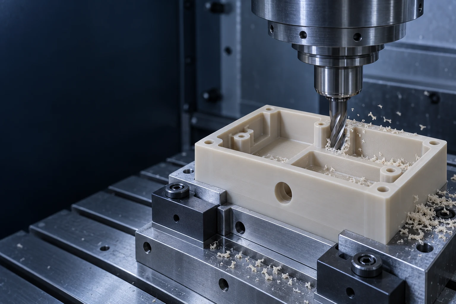
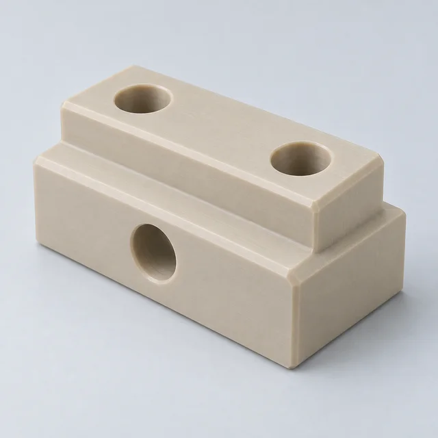
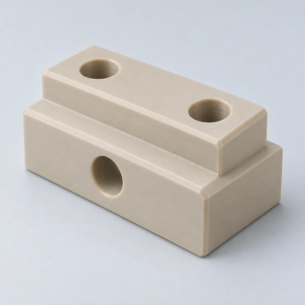
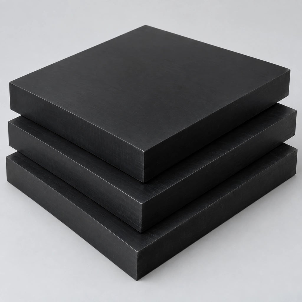
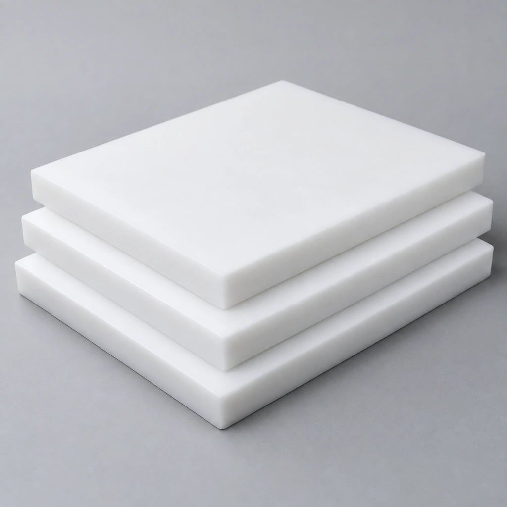
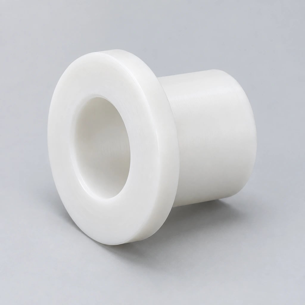
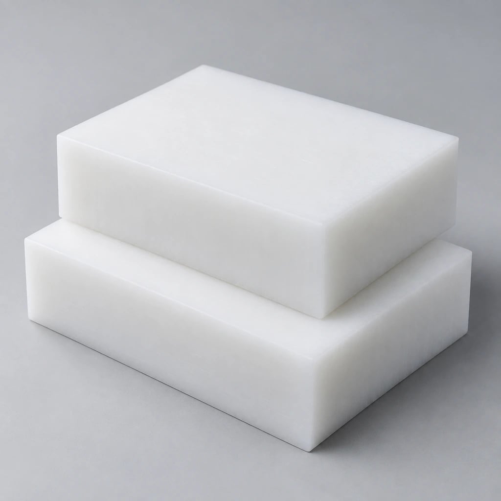
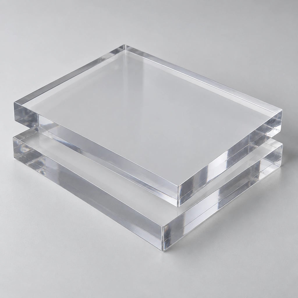
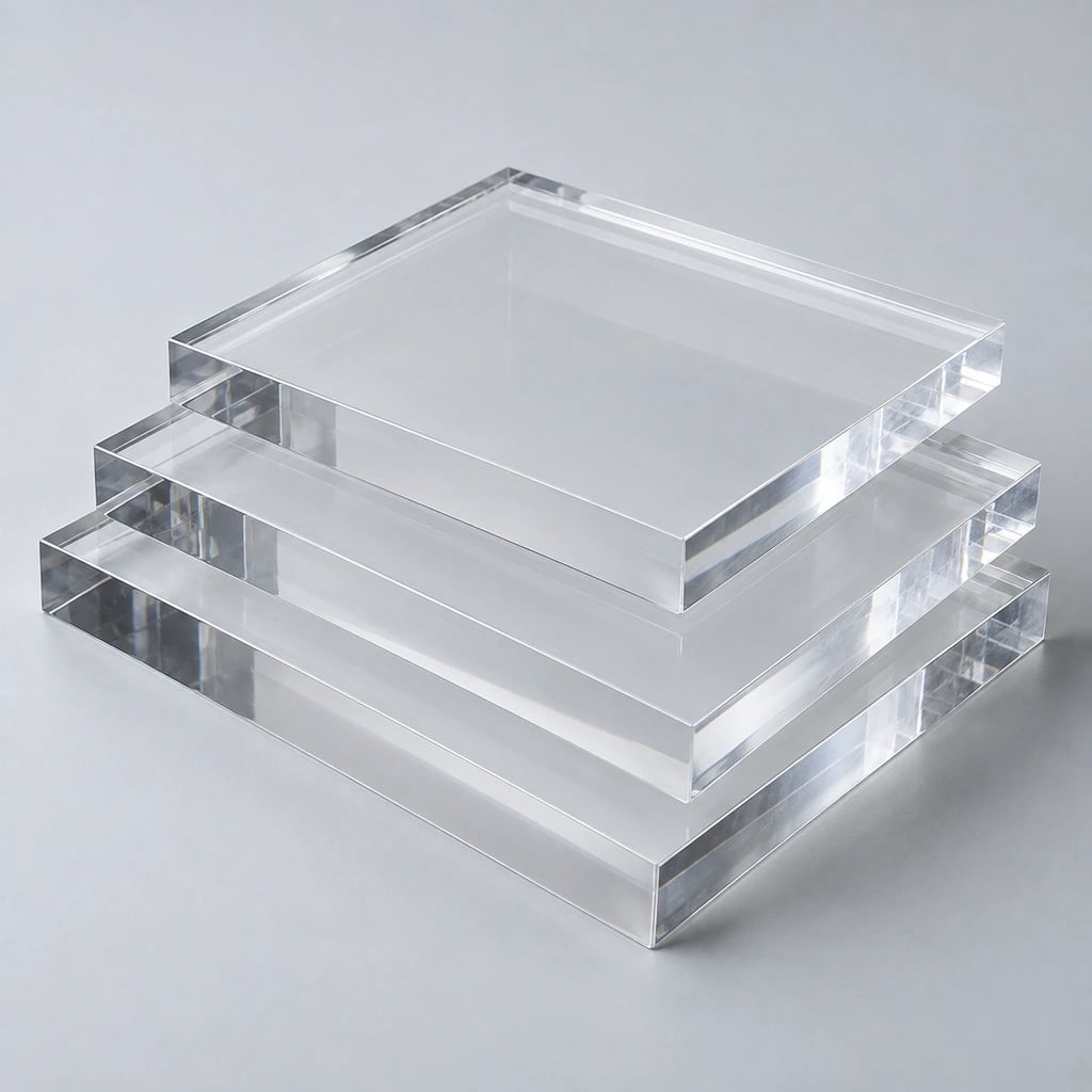
TOPS Plastics provides precision CNC milling services for custom components made from engineering plastics. From prototypes and fixtures to complex production parts, we machine PEEK, Delrin/POM, PTFE, Nylon, UHMW, Polycarbonate, Acrylic, Ultem and other high-performance polymers from your drawings or CAD files.
Start with the features your component needs: pocket depth, hole location, mating faces and access to each side. This snapshot describes the process routes available for review; the accepted manufacturing scope is confirmed against your drawing.
Capability
TOPS Plastics
Process
CNC milling of engineering-plastic stock
Machining
3-axis, 4-axis and 5-axis; selected after geometry review
Operations
Milling, drilling, boring, tapping, slotting and profiling
Dimensional inspection to the drawing and agreed inspection plan
Manufacturing
OEM / custom drawing-based parts
Machine travel, maximum component dimensions, spindle speed, maximum part weight, numerical tolerance capability and surface roughness are not blanket promises. Send the model, stock grade and critical dimensions so these limits and lead time can be confirmed for your project.
What Is CNC Milling?
CNC milling is a subtractive manufacturing process in which computer-controlled rotating cutters remove material from a supported workpiece. Tool paths create pockets, slots, holes, contours, flat faces and complex three-dimensional surfaces.
For plastics, the starting material is usually a plate, sheet, block or other suitable stock shape. Milling is useful when functional geometry, selected engineering polymers or smaller production volumes make a dedicated molding tool impractical. The model describes the shape; the drawing identifies the datums, tolerances and surface requirements that determine acceptance.
Typical CNC milled plastic parts include housings, manifolds, fixture plates, insulators, guides, brackets and gears. Unlike a purely cylindrical turned part, a milled component may need several tool approaches. Cutter access, pocket depth and support during material removal therefore influence both feasibility and cost.
The simplest workable setup is often the most economical. Extra axes are valuable when they improve access or preserve relationships between features; they do not remove the need for rigid support, suitable tools and measurable requirements.
3-Axis CNC Milling
Three linear axes suit plates, open pockets, holes, slots, straightforward housings and fixtures. Parts with accessible top features can often be produced efficiently with conventional setups. Features on the underside may require a second setup, with datum transfer and support reviewed before machining.
4-Axis CNC Milling
A rotary axis allows indexed access around a component and can simplify machining on several faces. It is useful for radial features, cross holes and some cylindrical stock parts that also need milling. Fixture clearance, rotary travel and the chosen indexing strategy determine practical access.
5-Axis CNC Milling
Five-axis milling can reach compound angles and multiple surfaces with fewer setups, supporting controlled positional relationships on complex manifolds, precision housings and equipment components. Whether indexed or simultaneous motion is appropriate depends on geometry, collision clearance, tooling and inspection.
Drilling, tapping, reaming, boring, engraving, countersinking, counterboring and chamfering complete functional details. Identify thread specifications, insert requirements and deburring expectations on the drawing. Deep holes, small cutters or difficult access may require a separate operation rather than one universal tool path.
3-Axis, 4-Axis & 5-Axis CNC Milling
Choose an axis configuration around feature access, setup count and the relationship between critical surfaces. More axes can reduce repositioning, but the best route is the one that supports the plastic part and meets its drawing requirements.
Milling route
Useful geometry
What to review
3-axis
Open pockets, plates, slots and accessible flat faces
Number of setups and underside access
4-axis
Indexed multi-face and radial features
Rotary fixture clearance and datum relationships
5-axis
Compound angles and complex surfaces
Tool reach, collision clearance and measurement access
Send the CAD model together with the drawing so tool reach, fixture clearance and inspection access can be assessed. An open plate may need only three-axis milling, while angled ports or multi-face features may justify an indexed rotary setup or five-axis approach.
Select a grade for the working environment before optimizing the milling route. Temperature, chemical exposure, stiffness, wear, moisture and required documentation matter more than color or a generic polymer label.
PEEK
A candidate for elevated-temperature and chemically demanding parts. State the exact grade and fillers: unfilled and reinforced PEEK differ in tool wear, surface behavior and performance.
Low friction, stiffness and useful dimensional stability suit fixtures, gears and mechanical details. Delrin is an acetal homopolymer brand; specify homopolymer or copolymer instead of assuming interchangeability.
Chemical resistance and low friction support fluid and insulation applications. Low stiffness and creep require gentle, supported workholding and an inspection method that avoids excessive measurement force.
Toughness and wear behavior suit guides and mechanical parts. Moisture conditioning can change dimensions, so identify the Nylon grade and the expected inspection and operating environment.
Useful for wear pads, guides and handling equipment. Flexible sections and thermal movement need realistic tolerances, adequate support and installation clearances.
Impact resistance and transparency suit guards, covers and selected equipment components. Review cleaner compatibility, stress cracking and the required appearance of milled faces.
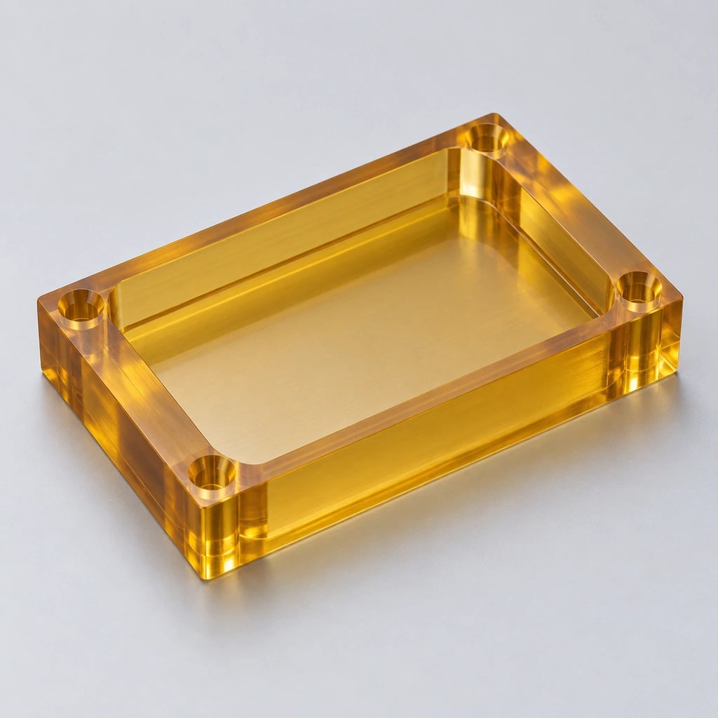
Transparent housings and visual parts may need a separately specified polishing operation. Milling alone does not establish optical clarity, and sharp transitions can concentrate stress.
Ultem / PEI
An option for elevated-temperature electrical and structural components. State the grade and required flame, electrical or other documentation; a family name does not establish approval.
Additional material
Milling and application considerations
ABS
Prototype housings; review toughness, appearance and working temperature
HDPE
Fluid and handling parts; review stiffness and thermal expansion
PVC
Rigid chemical-service parts; confirm formulation and media compatibility
PP
Lightweight chemical-service components; control deflection and support
PVDF
Chemical and semiconductor equipment; confirm grade and purity requirements
Torlon / PAI
High-performance parts; review stock condition and any required post-treatment
PPS
Thermal and chemical service; specify reinforcement and stock grade
PET
Mechanical and wear components; review stock condition and required fits
G10 / FR4 machining is not listed as a confirmed service. Send the laminate specification for capability review before requesting a quotation. For food-contact, medical or other regulated applications, identify the exact standard, contact conditions and supporting material documents.
CNC milling accuracy depends on material stability, component size, wall thickness, feature geometry, temperature and inspection conditions. Specify the functional dimensions that need tight control rather than applying one narrow tolerance to every surface.
Factor
Effect on milling accuracy
Material type
Stiffness and thermal expansion differ between grades
Wall thickness
Thin sections can flex under cutting or measuring forces
Part size
Longer dimensions experience greater absolute thermal movement
Internal stress
Asymmetric stock removal can release stress and change shape
Workholding
Excessive pressure can distort pockets, faces and holes
Temperature
Inspection and service temperatures can produce different dimensions
Moisture
Nylon and some other polymers change with moisture conditioning
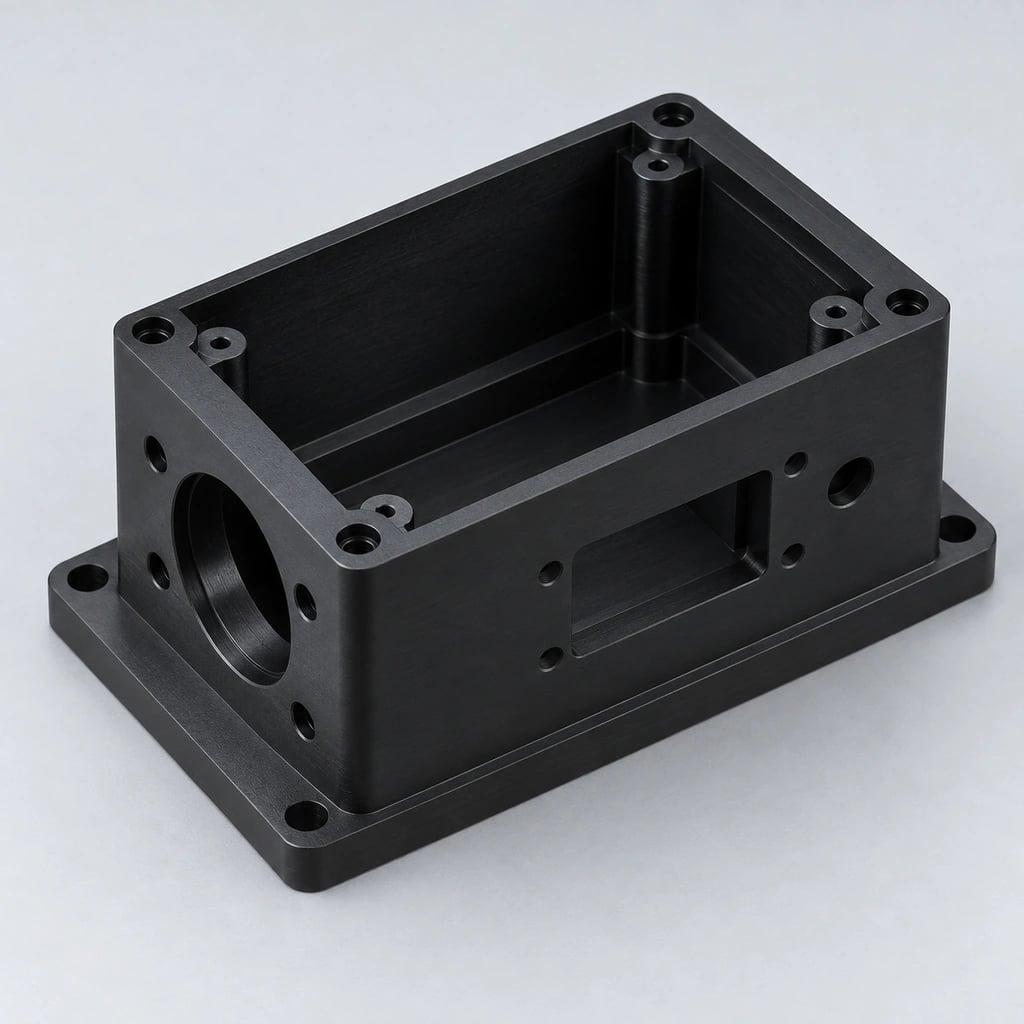
For a milled housing, define the datum face, mounting-hole positions, pocket width and any sealing land separately. Deep pocket walls may deflect differently from a thick mounting base. Ask how the part will be supported and checked after unclamping, not only whether the machine can position accurately.
Agree measurement temperature, conditioning and instrument contact force where these affect acceptance. Numerical tolerances, flatness and finish are confirmed after review of the grade and geometry; no universal ±0.005 mm promise is made.
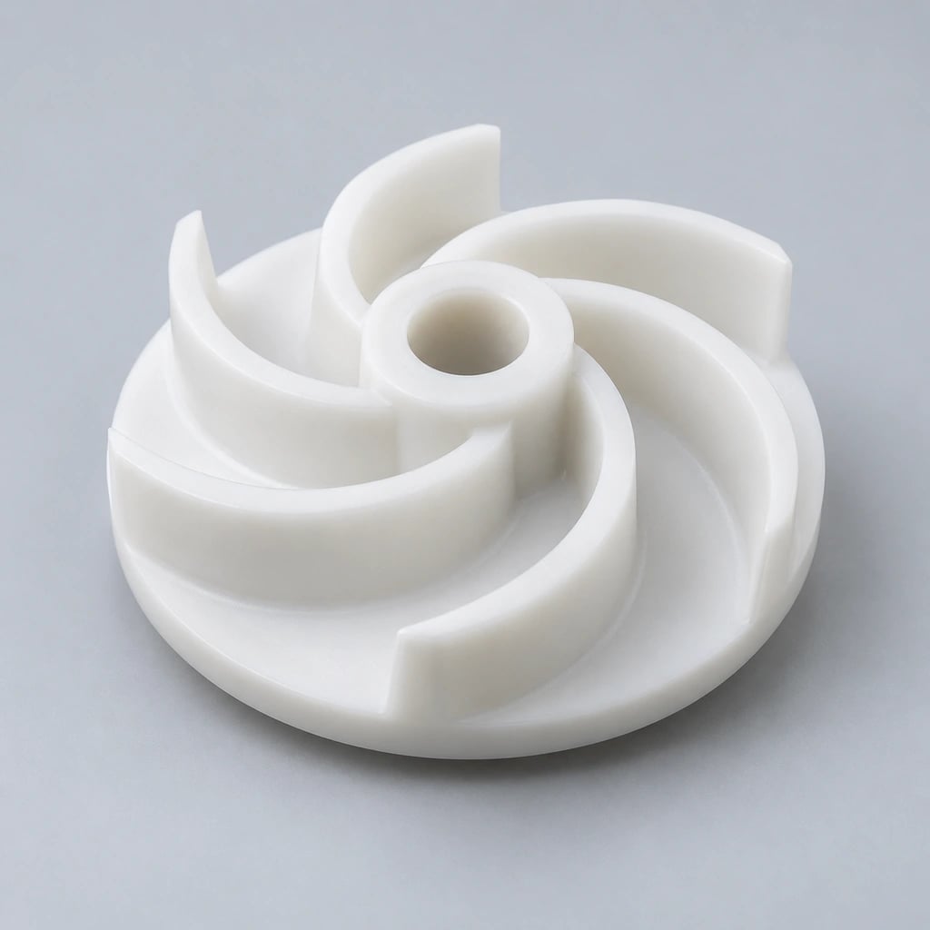
These part families show where milling creates useful geometry. Each item is manufactured to the customer's drawing; images illustrate component concepts rather than fixed catalog dimensions or verified customer projects.
Plastic Plates
Located holes, slots and recessed faces support mounting and equipment interfaces.
Plastic Housings
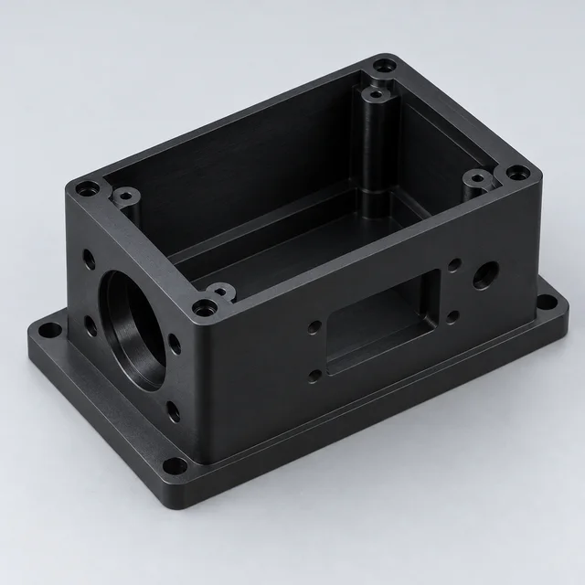
Pockets, cover interfaces and threaded details need a coordinated datum scheme.
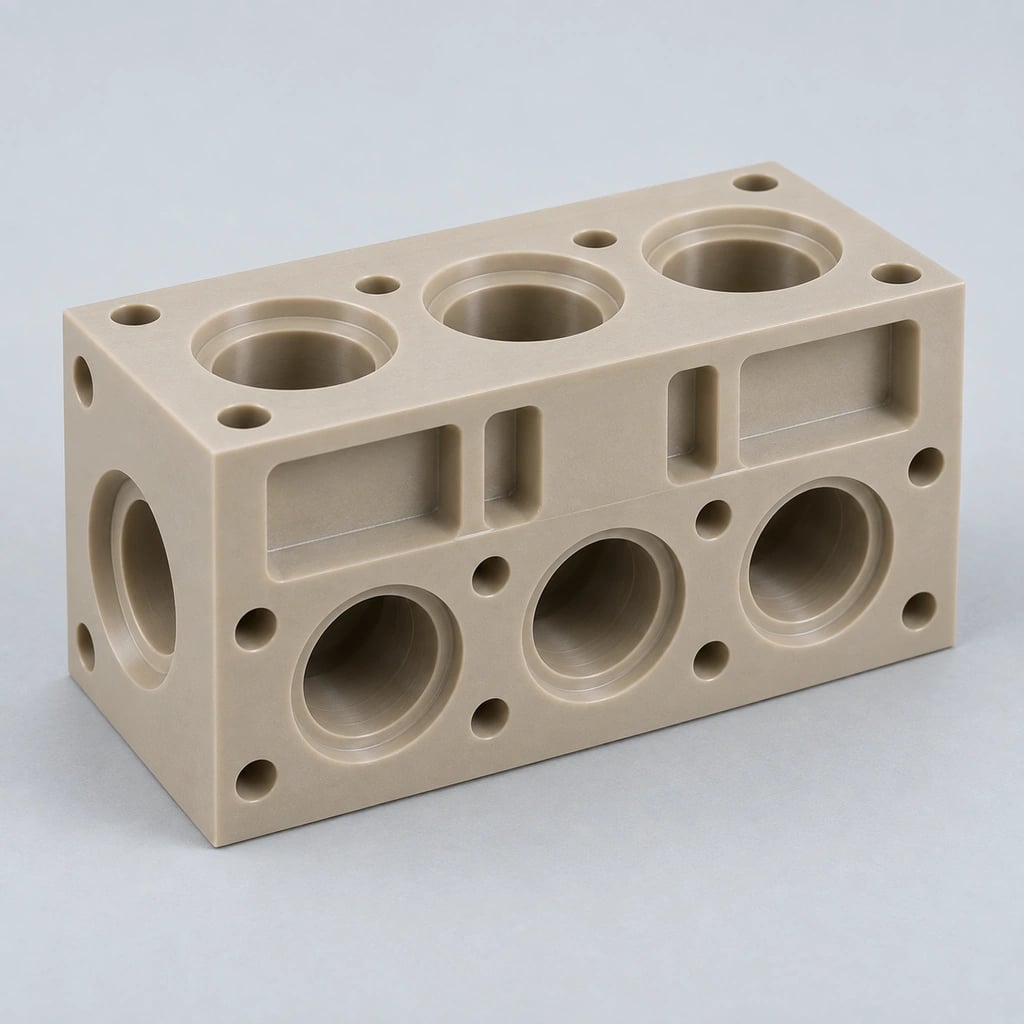
Plastic Manifolds
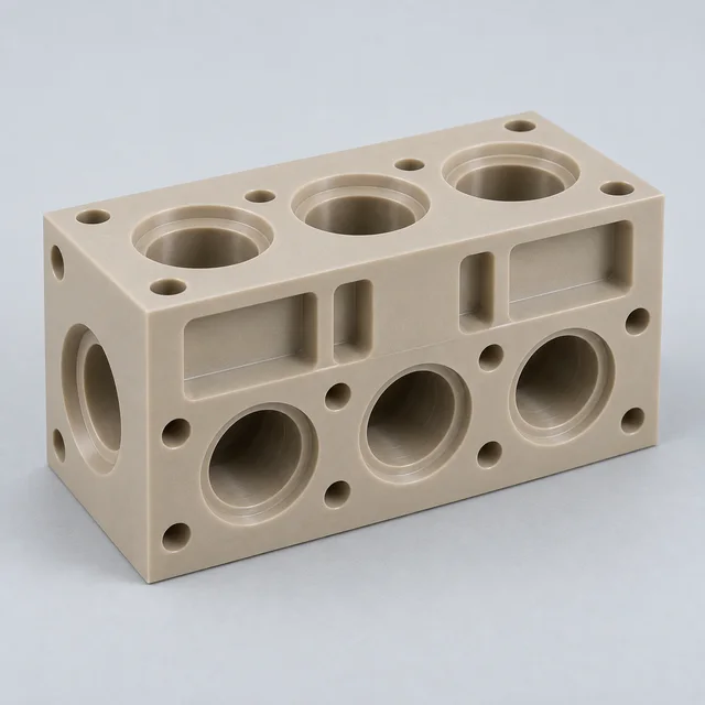
Intersecting passages, ports and sealing lands require fluid compatibility and access review.
Plastic Insulators
Mounting geometry must meet the specified electrical and environmental requirements.
Plastic Fixtures
Supported locating surfaces hold components for assembly, testing or measurement.
Plastic Jigs
Hole patterns and reference surfaces guide a defined manufacturing operation.
Plastic Brackets
Mounting faces, loads and installation access define the structural detail.
Plastic Guides
Profiles and slots guide moving products while accommodating wear and expansion.
Plastic Gears
Tooth geometry, mating conditions and loads guide material and machining review.
Plastic Machine Components
Custom interfaces, wear features and pockets integrate into industrial equipment.
Semiconductor Components
Fixtures and process-related parts require explicit purity and chemical requirements.
Medical Plastic Components
Equipment housings and fixtures are reviewed against the defined device requirements.
Good milling drawings allow cutters to reach the features and show how the finished component must function. These are design review questions, not fixed minimum dimensions that apply to every plastic.
Avoid Excessively Thin Walls
Thin walls and pocket floors can flex during cutting or move after stock removal. Review wall height together with thickness and available support. A thicker local section or a different pocket arrangement may improve manufacturability without changing the interface.
Use Practical Internal Radii
Rotating cutters leave a radius at internal corners. Smaller radii often require smaller, less rigid tools and longer cutting time, particularly in deep pockets. If a sharp corner is essential, discuss relief features or an alternative construction rather than silently replacing the CAD geometry.
Define Critical Tolerances
Identify the surfaces that locate the component in its assembly. Give functional fits and positions a clear datum reference, and leave noncritical dimensions appropriately toleranced. A 3D model alone usually does not communicate these acceptance conditions.
Consider Material Movement
Thermal expansion, moisture and released stock stress can change a pocket or plate after milling. Specify conditioning where relevant and review inspection after unclamping. Do not assume a metal design's clearance remains suitable when the material changes to plastic.
Specify Threads Carefully
State thread size, depth, engagement, assembly torque requirements and repeated-use expectations. Some applications may benefit from inserts or through-fastening. Insert installation, pull-out behavior and local wall thickness require separate review.
Identify Functional Surfaces
Mark sealing faces, bearing fits, alignment features and appearance-critical areas. For deep pockets and undercuts, show tool approach and assembly needs. Surface finish, burr limits and whether polishing is required should be agreed rather than inferred from a rendering.
Why CNC Milling Plastics Requires Specialized Process Control
Plastic milling needs a process selected for the polymer and the feature. A tool path that works well in metal may impose too much heat or force on a flexible pocket wall.
Heat Control
Most engineering plastics conduct heat less effectively than metals. Tool engagement, cutting conditions and suitable cooling must manage the cutting interface without damaging the grade. Coolant chemistry needs compatibility review, especially for stress-sensitive transparent polymers.
Sharp Cutting Tools
Appropriate cutting geometry and edge condition reduce rubbing and unnecessary cutting force. Reinforced grades can increase abrasion and tool wear. The choice is based on the polymer and operation rather than a single speed or feed recommendation.
Controlled Workholding
Fixtures must secure the part while avoiding imposed distortion. Support around open pockets, long plates and thin floors is particularly important. Check critical features in the agreed free or installed condition after release.
Chip Evacuation
Chips trapped in deep pockets can be recut and add heat or mark a finished surface. Tool paths and suitable evacuation should keep the cutting zone clear. Deep slots may need a different cutting sequence from an open-face pass.
Stress & Material Stability
Stock condition and one-sided material removal can affect flatness. Roughing, finishing allowances or material-specific stress-relief strategies may be reviewed when needed. Annealing is not automatically required or suitable for every grade and must follow supplier guidance.
For a thin-walled open housing, the review should connect pocket depth, cutter reach, support and the final inspection condition. For a thick manifold with cross passages, chip removal and bore alignment may be more important. These different risks need different process plans.
Share initial quantity, likely revisions and anticipated repeat demand. A practical milling quotation considers stock yield, fixtures, tool access and inspection effort across the expected order pattern.
Prototype CNC Milling
Functional prototypes can be produced without a dedicated injection mold. Use the specified stock grade to evaluate pocket access, assembly and mating fits. Keep model and drawing revisions aligned so test feedback refers to the part actually manufactured.
Low-Volume Production
Small batches suit specialized equipment, bridge production and custom fixtures. Setup effort can be significant relative to cutting time. Compare quoted quantities and required inspection scope instead of assuming a prototype unit price scales directly.
Repeat Production
Recurring orders need controlled revisions, grade specifications and agreed acceptance criteria. Identify how parts are labeled, which reports are required and what packaging protects the milled surfaces. Changes to a drawing or material should trigger renewed review.
CNC Milled Plastic Parts for Industrial Applications
Application requirements determine which material, geometry and documentation are suitable. Tell us the environment and intended use; an industry label alone does not define qualification.
Semiconductor
PEEK, PTFE and PVDF fixtures, insulators and compatible fluid components may support equipment projects. Specify cleanliness, chemical exposure and grade purity rather than assuming cleanroom suitability.
Medical Equipment
Precision housings, test fixtures and equipment components need review of cleaning, sterilization and any patient-contact requirements. Material documentation and device validation remain application-specific.
Aerospace
Lightweight brackets, spacers and high-performance polymer details must meet the drawing's temperature, load and material requirements. Do not replace a specified grade with a generic family name.
Automation & Robotics
Milled fixtures, guides, gears and mounts support motion and handling. Duty cycle, contact loads, wear and replacement access guide the review of geometry and material.
Electronics
Insulators, test fixtures and housings require defined dielectric, temperature and flame-related requirements where applicable. Mounting details and connection clearances should be shown.
Industrial Machinery
Wear guides, plates, fixtures and structural interfaces require the working temperature, mating surfaces and mounting constraints. Installation preparation should address expansion and clearance.
Fluid Handling
Milled manifolds and chemically resistant components need media, pressure, temperature and seal specifications. Cross passages and sealing lands are reviewed together; pressure testing must be requested and confirmed.
Inspection should demonstrate compliance with the agreed drawing under defined conditions. A pocket width, a hole pattern and a sealing face may need different measurement methods and sampling requirements.
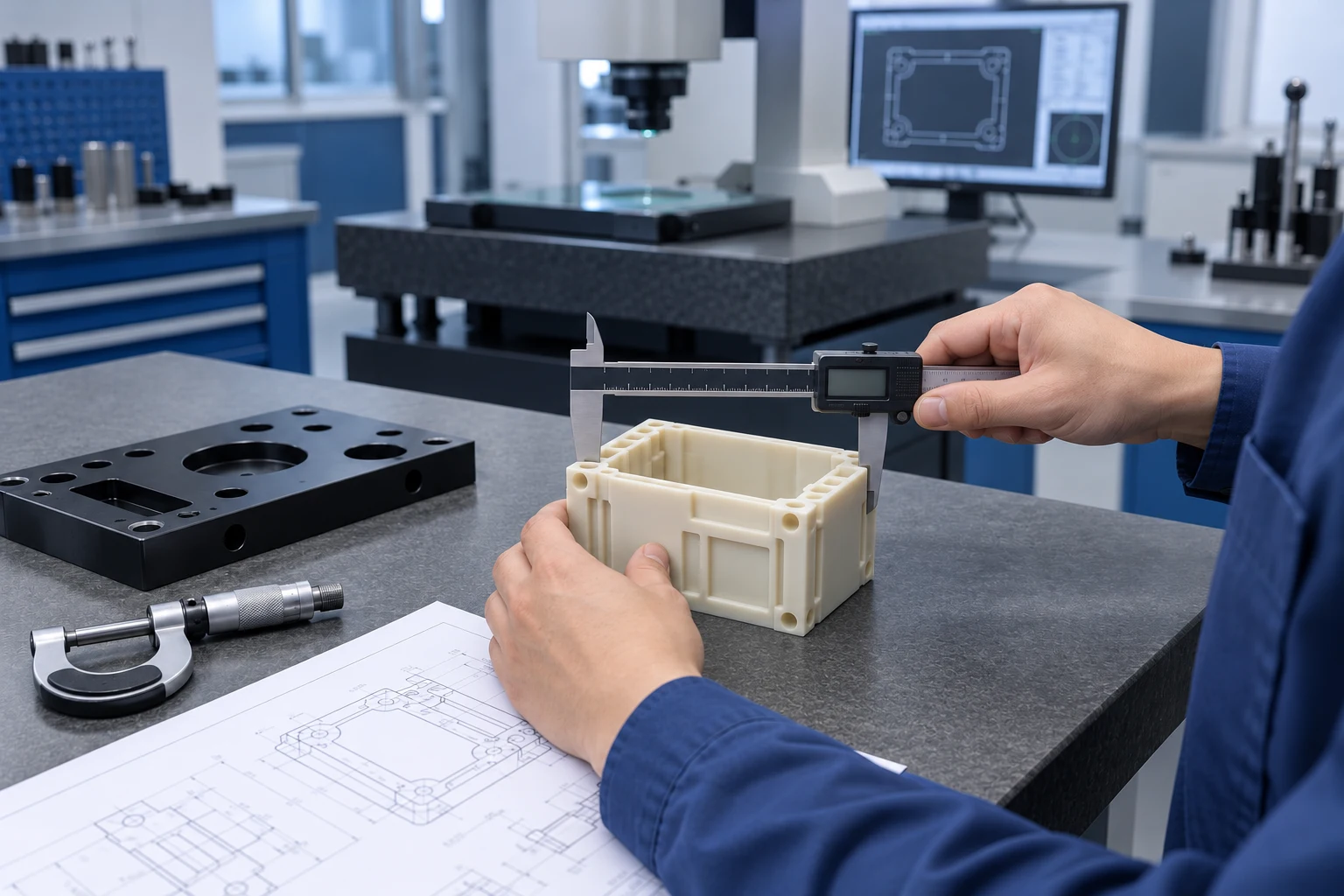
AI-generated manufacturing illustration; not a verified factory or customer photograph.
Material Verification
Confirm the specified grade and revision against the order and any agreed material documents before machining.
First Article Inspection
Check selected critical features on the first part, including datum relationships and dimensions affected by fixture release.
In-Process Measurement
Monitor agreed features during the batch to identify tool wear, thermal movement or changes in the workholding condition.
Final Dimensional Inspection
Measure applicable drawing requirements after machining in the agreed condition. CMM, optical measurement, calipers or micrometers are selected where appropriate; availability is confirmed for the project.
Inspection Report
Agree report format, feature numbering and sampling during quotation. A dimensional report is not automatically a material certification or application validation.
Packaging
Protect finished faces, pocket edges and threaded features before shipment. Specify identification, cleanliness and any export packaging or documentation requirements.
Actual factory photographs and project inspection records can be added when verified and approved for use. The accompanying image is an AI-generated manufacturing illustration, not evidence of a TOPS inspection record. Shipment inspection, pressure testing and additional reports must be explicitly included in the accepted scope.
CNC Milling vs CNC Turning for Plastic Parts
Choose milling for accessible prismatic features and complex faces; choose turning for geometry organized around an axis of rotation. Some components need both processes.
Factor
CNC Milling
CNC Turning
Cutting action
Rotating cutting tool
Rotating workpiece in conventional turning
Best geometry
Prismatic, multi-face and complex parts
Cylindrical or rotational parts
Typical features
Pockets, holes, slots and milled surfaces
Outside and inside diameters, grooves and threads
Typical plastic parts
Housings, fixtures, plates and manifolds
Bushings, rollers, sleeves and rings
Multi-face machining
Supported with suitable setups or additional axes
Limited in conventional turning; live tooling may add features
Complex 3D surfaces
Produced with appropriate cutters and tool paths
Generally limited for non-rotational surfaces
A plastic sleeve with a tight bore and an external mounting flat may be turned first and then milled. The route must preserve the relationship between the bore and the flat. Specify the functional datums instead of choosing a process only from the component name.
A useful supplier conversation connects a milled feature to its material behavior and an inspection plan. Discuss these buying criteria with our project team rather than relying on broad quality or price claims.
Engineering Plastic Expertise
Review grade, fillers, operating conditions and material movement alongside the pocket and wall geometry.
3-Axis to 5-Axis CNC Capability
Select an appropriate route after evaluating cutter access, multiple-face relationships and fixture clearance.
Precision Machining Support
Identify the dimensions and surfaces that control fit, sealing or alignment and agree measurable acceptance criteria.
Prototype to Production
Plan functional samples, low-volume batches and recurring orders around identified revisions and quantities.
DFM & Material Support
Review internal radii, deep pockets, thin walls, thread engagement and potential design adjustments before manufacturing.
Dimensional Inspection
Confirm measurement conditions, report availability and scope before production rather than assuming every test is included.
How We CNC Mill Your Plastic Parts
Each stage uses the agreed model, drawing revision and material specification. Missing functional information is resolved before the manufacturing scope is accepted.
01 — Upload CAD & Drawing
Share the model and annotated drawing, quantity and application. Mark critical interfaces and any conditions needed for inspection.
02 — Engineering Review
Review tool access, pocket depth, wall support, datums and finish. Clarify features that are difficult to reach or measure.
03 — Material Confirmation
Agree the stock grade, fillers and any required documents. Confirm availability and whether conditioning is relevant.
04 — CAM Programming
Plan cutter selection, roughing and finishing paths and safe approaches. Fixture clearance and the order of operations are considered together.
05 — CNC Milling
Machine the component using the reviewed setup and cutting conditions. Apply agreed in-process checks where required.
06 — Inspection
Check drawing requirements in the defined condition after machining. Prepare the agreed dimensional report and identify any nonconformity for resolution.
07 — Finishing / Assembly
Complete agreed deburring, polishing, insert installation or assembly where applicable. These operations are included only when specified and confirmed.
08 — Packaging & Shipping
Protect the finished parts and identify the batch or revision. Arrange shipment and documentation according to the accepted order terms.
CNC Milling FAQs
Direct answers to common milling, material and supplier-selection questions.
What plastics can be CNC milled?+
Many engineering plastics can be CNC milled, including PEEK, POM, PTFE, Nylon, UHMW, PC, PMMA, PEI, ABS, HDPE, PVC, PP, PVDF, PAI, PPS and PET. Feasibility depends on the exact grade, stock form, geometry and application requirements; send those details for review.
What is the difference between CNC milling and CNC machining?+
CNC milling is one type of CNC machining, using rotating cutters to remove stock. CNC machining is the broader category and can also include turning and other operations. A custom component may use more than one process to achieve its features.
How accurate is CNC milling for plastic parts?+
Plastic milling accuracy is material- and geometry-dependent, so critical tolerances require a drawing review. Thin walls, thermal expansion, moisture and stock stress can influence the finished dimensions. Define the datums and inspection conditions instead of relying on one tolerance number for every part.
Can PEEK be CNC milled?+
Yes, PEEK can be CNC milled into housings, fixtures, manifolds and other custom components. Specify the grade and reinforcement because they affect tooling, stock behavior and performance. Review deep pockets, thin walls and any grade-specific documentation requirements.
Can PTFE be CNC milled accurately?+
Yes, PTFE can be CNC milled, but its low stiffness and creep require realistic feature-specific tolerances. Supported workholding and suitable measuring force help avoid distortion during cutting and inspection. Critical bores or sealing details need review against the actual service conditions.
Is CNC milling suitable for prototypes?+
Yes, CNC milling is suitable for functional plastic prototypes without a dedicated injection mold. It can reproduce pockets, mounting details and interfaces in a specified stock grade. A milled prototype does not automatically reproduce every property or economic characteristic of a later molded part.
What is the difference between CNC milling and CNC turning?+
Milling conventionally uses a rotating cutter; turning conventionally rotates the workpiece. Milling suits pockets, slots and multiple faces, while turning suits bores, diameters and rotational profiles. Parts combining these features may require both processes.
What drawing files do you accept for CNC milling quotes?+
We accept STEP/STP, IGES, X_T, DWG, DXF and PDF for review. Pair a CAD model with an annotated drawing showing material grade, revision and critical requirements. The optional upload accepts one file or ZIP package up to 10 MB; larger files can be shared by email.
Is 5-axis CNC milling necessary for complex plastic parts?+
No, complex parts do not always require 5-axis milling. Several 3-axis or indexed 4-axis setups may be suitable when access and datum transfer can be controlled. Five-axis machining is considered when compound angles, multiple surfaces or setup reduction justify it.
YOUR MILLED PART. YOUR REQUIREMENTS.
Get a Quote for CNC Milled Plastic Parts
Upload your CAD model or engineering drawing and provide the plastic material, quantity, dimensional tolerances, surface requirements and application information. Our team will review manufacturability and provide a quotation for your custom CNC milled plastic components.
For an efficient review, identify pocket depths, internal radii, wall thickness, mounting datums and any critical sealing or alignment surfaces. If the material is undecided, describe the temperature, media exposure, loads and wear conditions. Project specifications and the drawing upload are optional; company, name, email and phone are required.
STEP / STP / IGES / X_T / DWG / DXF / PDF or ZIP, maximum 10 MB. Larger files can be shared by email. Please agree confidential-file handling before sending sensitive drawings.