01
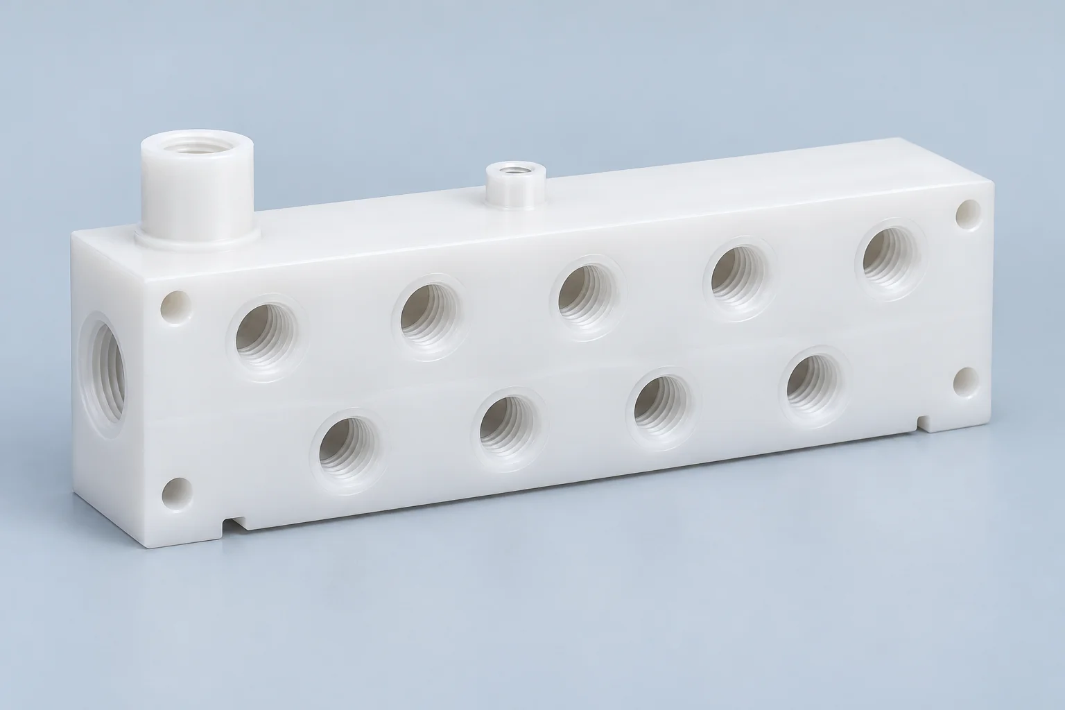
Plastic Manifolds
Multi-port blocks for fluid distribution, chemical routing, pneumatic control, vacuum equipment and instrument flow paths.
Explore component details →
MEDIA · SEALING · FLOW GEOMETRY
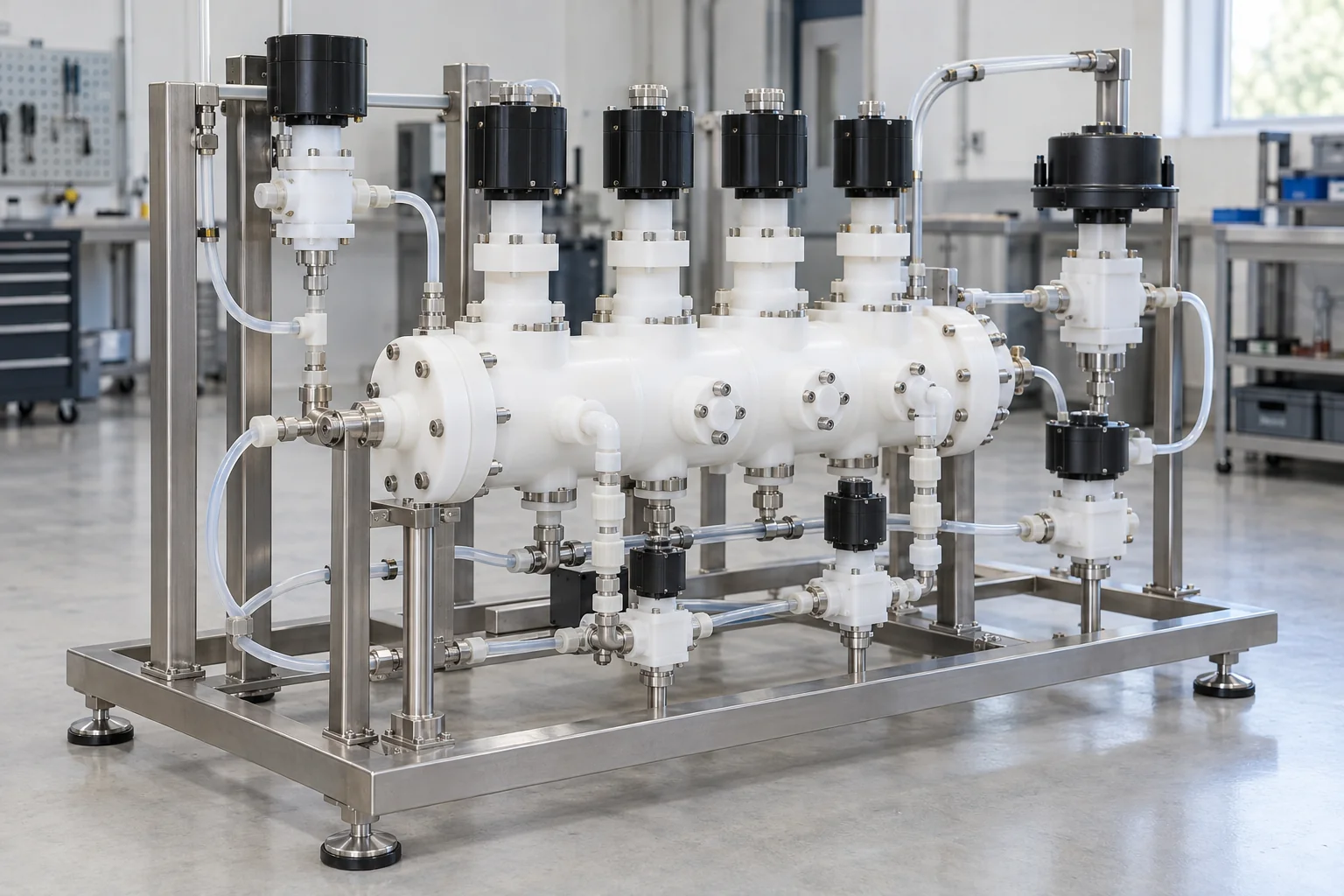
TOPS Plastics manufactures custom CNC machined plastic components for pumps, valves, manifolds, chemical delivery systems, pneumatic equipment, water treatment systems and industrial fluid-control assemblies. We machine PVDF, PTFE, PEEK, PVC, PP, PPS and other engineering plastics according to customer drawings, fluid media, pressure, temperature and sealing requirements. CPVC requests can be reviewed for exact grade and stock availability.
Define the media, operating envelope and sealing concept before reviewing the machining route.
| Capability | TOPS Plastics |
|---|---|
| Typical parts | Manifolds, valve blocks, pump housings, fittings and spacers |
| Materials | PVDF, PTFE, PEEK, PVC, PP, PPS and specified grades; CPVC subject to review |
| Processes | CNC milling, turning, 5-axis machining, drilling and tapping |
| Key requirements | Chemical compatibility, sealing, pressure and dimensional stability |
| Production | Prototype, low-volume and repeat production |
| Input | STEP, CAD, 2D drawings and reference samples |
| Inspection | Port position, sealing features and drawing dimensions |
| Documentation | Material and inspection documents where specified and available |
Begin with the manifold or flow-system function, then define the material, ports, sealing features and acceptance requirements.
Multi-port blocks for fluid distribution, chemical routing, pneumatic control, vacuum equipment and instrument flow paths.
Explore component details →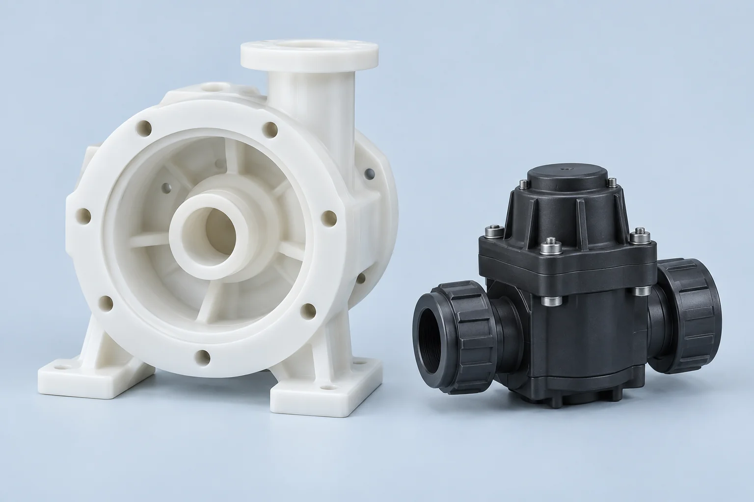
Pump and valve bodies, sensor housings and flow-control structures with defined cavities, sealing faces and mounting interfaces.
Explore component details →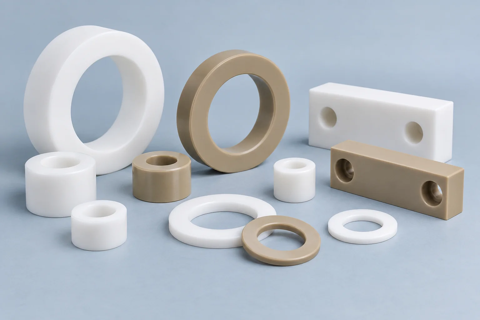
Valve-stack spacing, electrically isolated fluid-system supports and assembly spacers with specified grade and fit.
Explore component details →Plastic Insulators →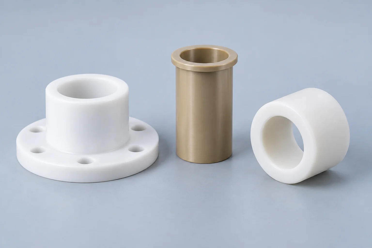
Stem and shaft guides for valves, pumps and actuators, matched to movement, fluid exposure and running clearance.
Explore component details →Plastic Bearings →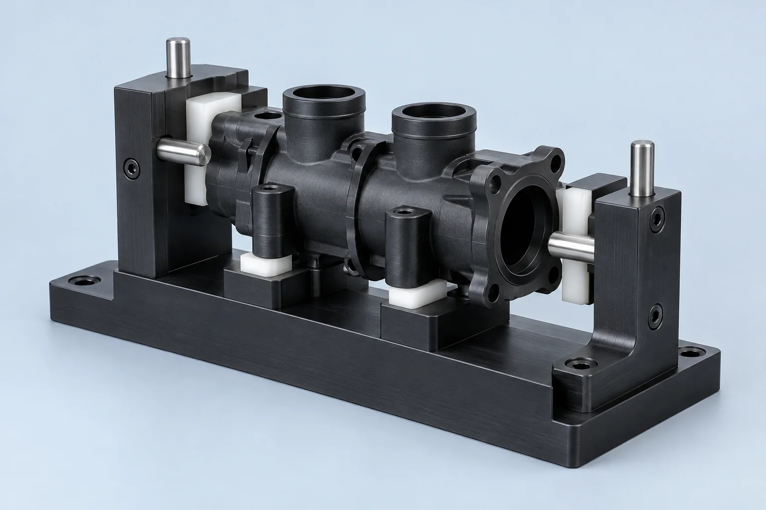
Assembly and inspection nests, tube-positioning tooling and fixtures for a customer-defined leak-test setup.
Explore component details →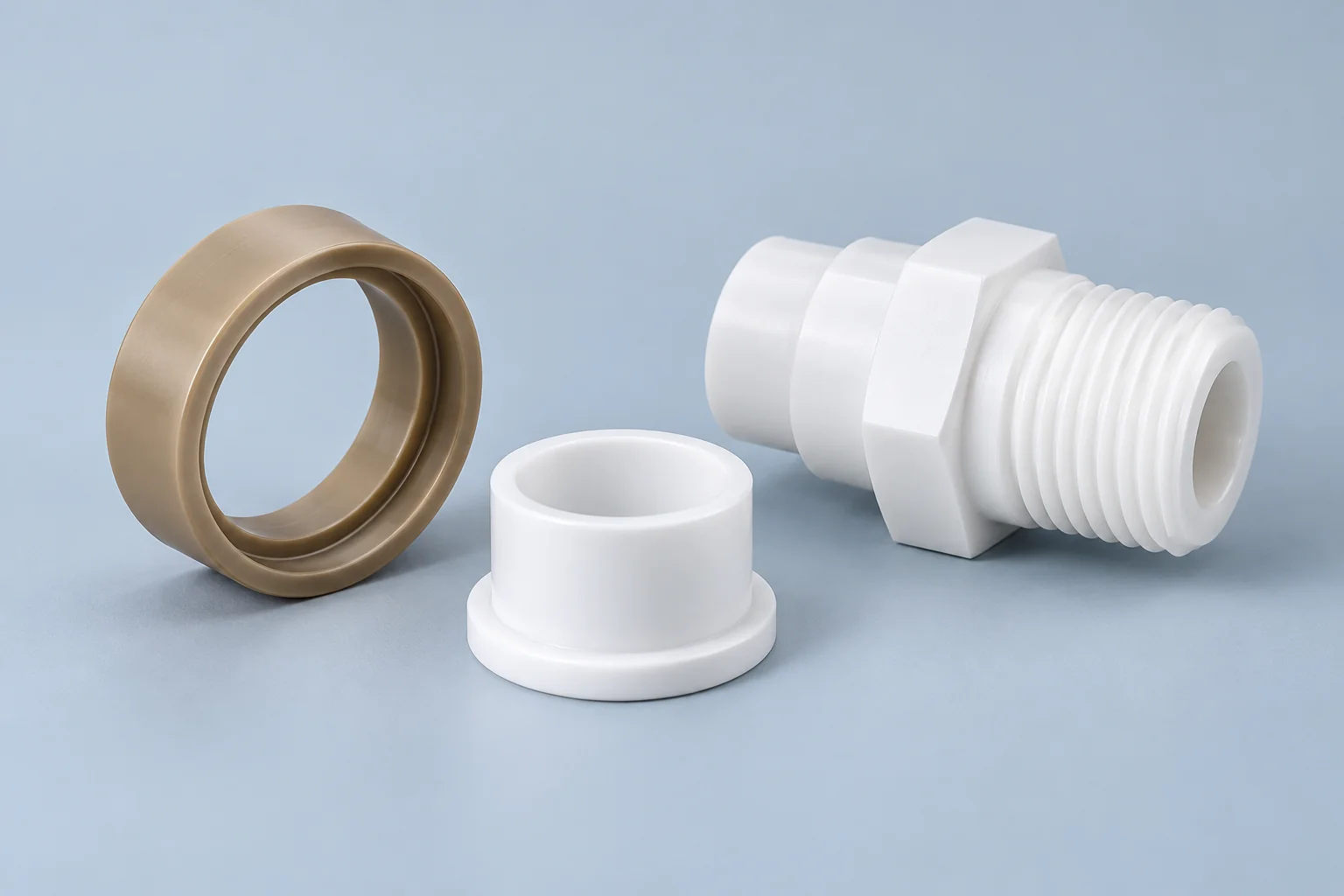
Drawing-based valve seats, fittings, sleeves, flow blocks and nonstandard pump or manifold components.
Explore component details →System type, part function and engineering requirement determine the component specification.
Housings, impeller-adjacent components, bushings, wear rings, spacers and guides need chemical compatibility, stable fits, wear control and suitable temperature performance.
Bodies, seats, guides, stem bushings, spacers and actuator interfaces combine sealing, creep, media compatibility and moving fits.
Multi-port blocks, distribution plates, cross-drilled manifolds and chemical-routing blocks require accurate port positions, channel intersections, seal features and burr control.
PVDF manifolds, PTFE parts, PEEK valve components, fittings and support blocks need exact chemistry and purity requirements. General chemical resistance does not establish high-purity suitability.
Manifolds, valve blocks, housings, guides and spacers must match treatment chemicals, temperature, connection design and the intended water service.
Manifolds, fittings, valve blocks, vacuum housings, seals and supports need defined gas, pressure differential, leakage criteria and any outgassing requirement.
There is no single best material. Review chemical compatibility, mechanical support, temperature, connection design and required evidence together.
| Material | Main advantage | Typical fluid-system use |
|---|---|---|
| PVDF | Chemical resistance and stiffness; purity depends on grade | Chemical manifolds and specified purity applications |
| PTFE | Broad chemical compatibility and low friction | Aggressive-media candidates, seats and sliding parts |
| PEEK | Strength, temperature and chemical performance | Higher-performance valve and pump components |
| PVC | Economical chemical-service options | Water and process-fluid equipment |
| CPVC | Candidate for elevated-temperature chemical service | Hot-fluid systems, subject to grade and stock review |
| PP | Chemical resistance and economical stock | Process-fluid blocks and supports |
| PPS | Chemical and thermal stability | Precision technical fluid parts |
| POM / Delrin | Precision and machinability | Mechanical components in compatible lower-demand service |
This is a selection framework, not a universal chemical compatibility chart. Confirm exact resin, additives, supplier data, media concentration and operating conditions. CPVC is distinct from PVC; a link to the PVC material page does not establish interchangeable properties or confirmed CPVC stock.
Multiple ports, cross-drilled passages, threaded interfaces, O-ring grooves, valve mounts, sensor ports and drains must work as one fluid-routing design.
Control port-to-port and port-to-mounting relationships from functional datums. Include fitting envelopes and assembly access.
Channel size, length and transitions influence flow and pressure loss. Supply the flow requirement rather than assuming any drilled hole is equivalent.
Align intersecting passages and retain sufficient wall around them. Identify all intersections for deburring and inspection planning.
Analytical, chemical and specified purity systems may require reduced retained volume. Define allowable pockets and flushing requirements.
Specify plugs, covers or other closure method, sealing details and acceptance criteria. Manufacturing access holes remain part of the pressure boundary.
A manifold is more than a block with drilled holes. Port relationships, channel intersections, sealing surfaces, wall thickness, media compatibility and internal burr control determine how it integrates into the fluid system. Plastic Manifolds is the detailed component page for these drawing and interface requirements.
Valve bodies, guides, stem bushings, seats, pump housings, wear rings and flow blocks need both chemical and mechanical review.
Define steady, peak and cyclic conditions. Strength and retained seal geometry can change with temperature and time.
Identify fluid or gas, concentration, exposure and any cleaning media. Compatible material is necessary but not sufficient for component function.
Specify travel, speed, counterface, clearance and lubrication. Include wear, alignment and frictional heat.
Review the supported section, retained loads and acceptable shape change. A chemically resistant material may still deform under sustained load.
Select valve and pump parts for fluid compatibility and mechanical performance together. The grade must maintain the required shape, fit and seal geometry within the operating envelope. Agree representative validation where the application requires it.
Seal performance depends on the complete gland, mating material, pressure, fluid and temperature. A machined groove alone does not guarantee a leak-tight assembly.
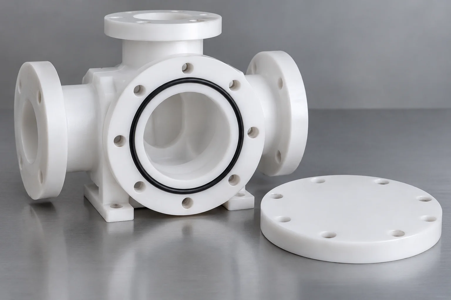
Release groove width, depth, corner radii and surface condition with the selected seal. Squeeze, stretch and gland fill depend on the complete design and service.
Specify flatness, finish, gasket material and clamping arrangement. Sustained compression and plastic creep can change retained sealing load.
Shaft and cylindrical interfaces require controlled bores, concentricity and finish. Define static or moving service, pressure direction and clearance.
Depending on the interface, sealing may use thread form, sealant, an O-ring or a separate face seal. Identify the actual fitting and approved method.
Use seal-supplier design guidance and the released assembly specification. Polymer expansion, seal compatibility and fitting loads need joint review; dimensional inspection of the gland is separate from an agreed leak test.
NPT, BSP/BSPT, metric and straight threads, O-ring boss style interfaces, hose barbs, flange patterns and custom ports can be reviewed against the drawing and tooling scope.
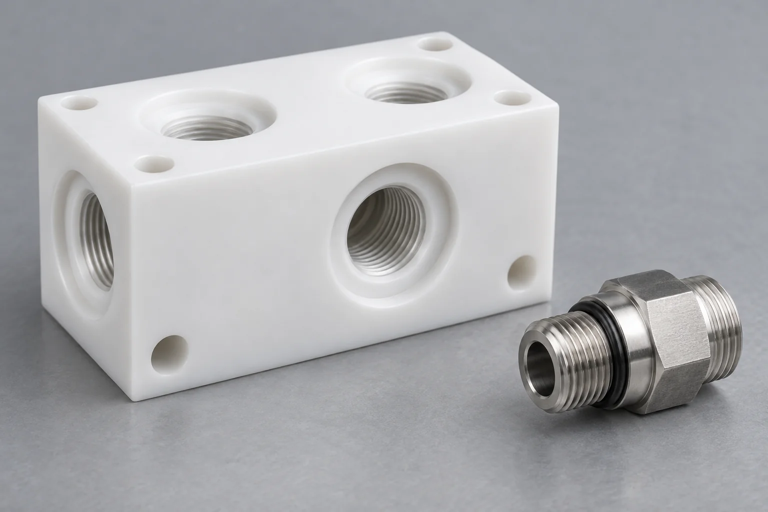
Retain adequate material around ports, intersections and edges. Tapered fittings can introduce hoop stress.
Specify thread standard, size, class and usable engagement. Include entry chamfer, sealing land and fitting envelope.
Agree fitting and seal installation requirements. Metal-fitting torque assumptions should not be transferred directly to a plastic body.
Sustained loads and dissimilar thermal expansion affect connections. Review fitting material, support and repeated installation.
Match engagement, wall thickness and installation torque to the polymer and connection design. Different BSP or NPT forms are not interchangeable. Specify the exact interface and where the seal occurs rather than relying on a general port label.
Pressure capability depends on grade, geometry, wall thickness, temperature and connection design; no universal material or manifold pressure rating applies.
State normal, maximum and transient pressure, including the direction and external loads.
Define target pressure and allowable leakage. Outgassing, permeation and seal behavior may matter for the application.
Provide flow, allowable pressure loss and any sensitivity to dead volume or flow disturbances.
Include continuous, peak and cleaning exposure. Temperature changes stiffness, expansion and connection fit.
Continuous service differs from intermittent exposure. Supply operating hours, dwell and start-stop conditions.
Repeated cycles can affect seals, fatigue-sensitive areas and retained closures. State frequency and expected life.
Plastic manifolds can handle pressure in suitable validated designs. Review the specific part and acceptance scope; a material datasheet or machining capability alone does not establish the finished assembly rating.
Check compatibility against exact grade, fluid, concentration, temperature and exposure duration. Include the mechanical stress and required purity.
List acids, bases, solvents, water, gases, oils, mixtures and cleaning agents. A broad chemical category may hide important differences.
Compatibility can change with concentration and mixed media. Include normal and upset conditions.
Higher temperature can change chemical behavior and mechanical properties. Use actual media and surface temperatures.
Distinguish splash, intermittent contact and continuous immersion, including exposure duration and cleaning cycles.
Pressure, threads and clamping introduce stress that can worsen environmental cracking or deformation.
Specify extractables, particles, residues or outgassing limits for semiconductor, pharmaceutical and analytical applications where relevant.
Supplier compatibility data is a screening input under stated conditions. Confirm relevant grade evidence and application validation where needed; chemical resistance does not prove universal purity, oxygen-service suitability or compatibility with every concentration.
Evaluate operating temperature and sustained load because creep and expansion can change seals, threads and port alignment over time.
Port relationships and plastic-to-metal fits can move with temperature. Allow for connection support and operating clearances.
Sustained pressure or clamp load can deform a polymer. Consider section, support and time under load.
Many polymers lose stiffness as temperature rises. Review grade data under relevant loading conditions.
Compression can relax over time. Define bearing area, fastening method and retained sealing load.
Gland movement can change squeeze or clearance. Review the complete seal and body assembly across the service range.
High-temperature capability is not a single unloaded number. Compare strength, deformation and connection behavior at the intended duty, then agree the validation and inspection state for critical features.
Burrs and chips can restrict flow, contaminate systems or interfere with valves and seals. Passage quality is a functional requirement.
Plan removal and verification at drilled intersections. Hidden features need an accessible method agreed with the drawing.
Remove machining debris and interfering entry burrs without damaging port or seal geometry.
Define acceptable transitions and passage finish where flow, particles or retained volume matter.
Deep or enclosed channels can retain particles. Provide access, flushing paths or a specified cleaning method.
State residue, particle, drying and packaging criteria. General deburring does not establish high-purity cleaning.
Manifolds, valve blocks, sensor bodies, analytical equipment and chemical delivery systems may need different cleanliness levels. Define the acceptance method and documentation scope before quotation rather than relying on appearance alone.
Control sealing, port, bore and flow-path interfaces tightly where needed. Use practical limits on nonfunctional exterior surfaces.
| Feature | Why it matters |
|---|---|
| O-ring groove | Seal compression and gland geometry |
| Flat sealing face | Gasket seating and retained seal load |
| Port position | Fitting alignment and assembly access |
| Thread quality | Connection integrity and engagement |
| Bore diameter | Valve, stem and shaft fit |
| Cross-hole intersection | Flow continuity and burr control |
| Mounting face flatness | Assembly stability and supported alignment |
| Internal passage finish | Flow and cleanliness requirements |
Release datums, critical tolerances/GD&T, finish, inspection temperature and free or restrained state where relevant. Ports and sealing faces should be measured against their functional relationships rather than tightening all dimensions equally.
Resolve the fluid and operating envelope before releasing the part for manufacture.
Check compatibility before prioritizing cost. Include process and cleaning fluids.
They influence material choice, wall thickness, connections and validation.
Review edge distances, intersections and threaded-fitting loads.
Use a defined O-ring or gasket with appropriate compression, finish and support.
Define retained-volume and flushing requirements for analytical or specified purity applications.
Deep ports and intersecting channels affect machining and inspection feasibility.
Release the plug or cover design, sealing method and acceptance requirements.
Specify fluid-contact surfaces, internal passages, residues and packaging criteria.
Choose the process around ports, sealing features, stock form and the agreed inspection scope.
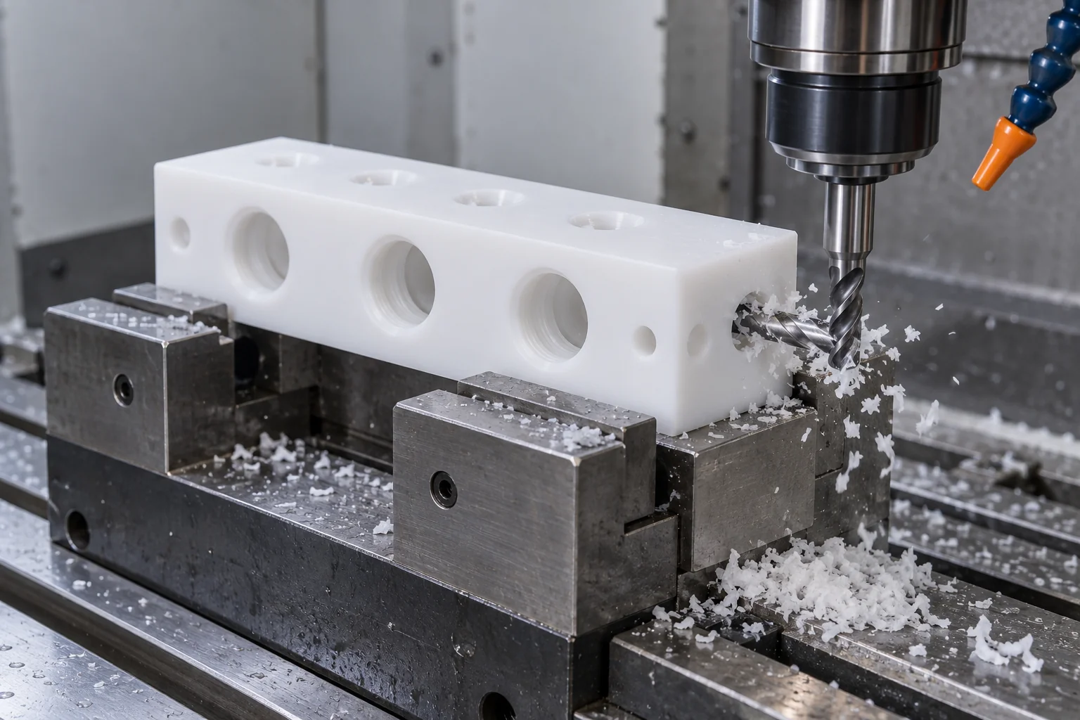
Machine manifold bodies, valve blocks, pump housings and sealing faces.
Create specified internal passages with tool-access and intersection review.
Produce bushings, valve components, fittings and sleeves around concentric interfaces.
Machine released ports and fitting threads with defined engagement and sealing lands.
Access multi-face or angled ports where geometry justifies the route.
Address fluid-path burrs and chips to an agreed accessible cleaning scope.
Verify ports, seal features, threads and critical drawing dimensions.
Project-specific leak, pressure, cleanliness and packaging requirements can be reviewed during quotation. Confirm feasibility, method and acceptance before order.
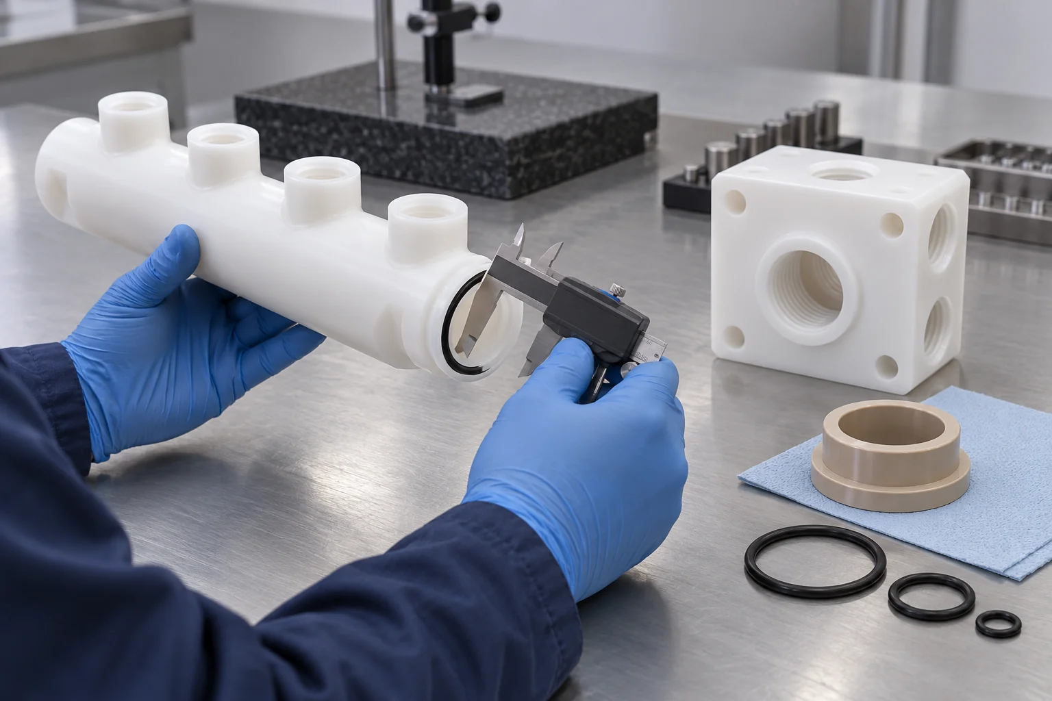
Confirm exact polymer grade and available requested supplier documentation.
Align released CAD, revision, functional datums and passage plan.
Check location and relationships to sealing and mounting references.
Verify specified thread form, engagement and connection features.
Inspect gland dimensions, face geometry and required finish.
Check accessible channel geometry and intersections using agreed methods.
Review edges, fluid paths and the specified cleaning criteria.
Confirm supported test scope, medium, conditions and acceptance separately; availability is project-dependent.
Protect ports and sealing surfaces under the agreed handling and cleanliness requirements.
Dimensional inspection does not establish zero leakage or a certified pressure/vacuum rating. Helium leak testing, cleanroom packaging and high-purity cleaning require specifically confirmed capability and scope. Request material and inspection reports early so their availability can be reviewed.
Control the material, geometry and cleanliness requirements as the design moves toward recurring supply.
Validate port layout, mating fit and sealing concept using the intended fittings and seals.
Confirm grade, chemical service, connection design and application tests under representative conditions.
Supply specialized process equipment to released drawings and agreed inspection criteria.
Maintain exact grade, released drawing, machining program, inspection criteria and cleanliness/packaging requirements.
Review media, concentration, pressure, temperature, sealing method, flow, cleanliness and dimensional stability as one complete process condition.
Review PVDF, PTFE, PEEK, PVC, PP, PPS and other specified grades against the exact media.
Connect ports, cross-drilled channels and multi-face features to machining and inspection access.
Machine drawing-defined O-ring grooves, gasket faces and threaded ports.
Processes for manifolds, housings, fittings and valve components.
Support development and recurring OEM orders with controlled releases.
Agree critical flow and sealing features, reporting and acceptance requirements.
Move from application requirements to the detailed product page for geometry, interfaces and drawing preparation.
Direct answers about chemistry, manifolds, seals, threads, pressure, vacuum and repeat supply.
PVDF, PTFE, PEEK, PVC, PP, PPS and compatible POM grades are candidates. CPVC can be reviewed separately for grade and availability. Select for the exact media and operating envelope.
There is no universal best material. Compare exact chemistry, concentration, temperature, pressure, exposure, sealing method and purity requirements before choosing the grade.
Consider PVDF where stiffness, machining and compatible chemical service suit the design. PTFE offers broad chemical compatibility but creep and mechanical support need particular review.
PEEK can be a candidate for demanding load, heat and chemical service. Confirm the actual grade, media, connections and sustained-load requirements.
Yes, suitable interfaces can be reviewed. Specify exact thread form and fitting, sufficient wall, engagement, torque and sealing method; different forms are not interchangeable.
Yes, in suitable validated designs. Capability depends on grade, geometry, temperature, pressure differential, connection and seal design; no universal rating applies.
CNC milling or turning can produce drawing-defined glands. Groove dimensions, radii, finish and datums must follow the selected seal and complete assembly requirements.
Check exact grade against each fluid, concentration, temperature and exposure duration, including stress, pressure and cleaning media. Use relevant supplier evidence and application validation.
Prioritize seal glands, sealing faces, ports, threads, bores and channel intersections. Define functional datums, finish and inspection state.
Yes, prototype, low-volume and recurring components can be reviewed. Release exact grade, CAD, quantity, operating conditions and inspection/cleanliness scope.
MEDIA. PRESSURE. TEMPERATURE. SEALING.
Upload your component drawing or CAD model and specify the exact material grade, fluid or gas media, concentration, pressure, temperature, flow requirement, port/thread specification, sealing method and critical tolerances. TOPS Plastics can review the geometry, material and machining feasibility before quotation.
Company, name, email and phone are required. Country, part number, quantity and drawing upload are optional. Include technical requirements in the drawing or email; combine CAD and supporting files into one ZIP if useful.
info@tops-precision.comSTEP / STP / IGES / X_T / DWG / DXF / PDF or ZIP, maximum 10 MB. Larger packages can be shared by email. Agree confidential-file handling before sending sensitive drawings.