01
Plastic Insulating Sleeves
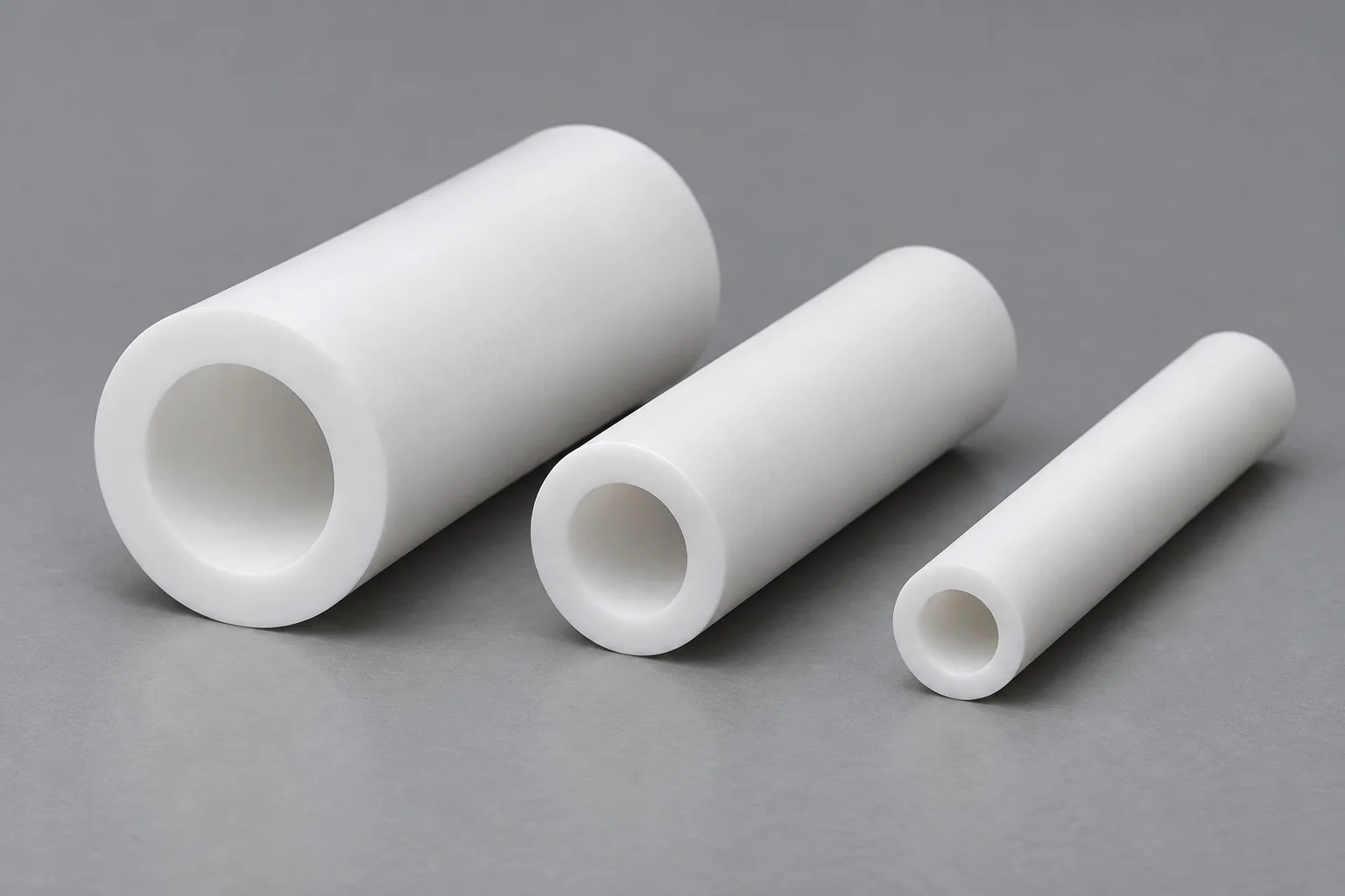
Precision sleeves electrically separate shafts, fasteners, terminals or other metal components.
Discuss this insulator →
ISOLATE. LOCATE. SUPPORT.
TOPS Plastics manufactures custom plastic insulators and electrically insulating components for semiconductor equipment, electronics, automation, test systems, medical equipment and industrial machinery. We machine PEEK, PEI/Ultem, PPS, PTFE, POM and other engineering plastics according to customer drawings, electrical requirements, operating temperature and application conditions.
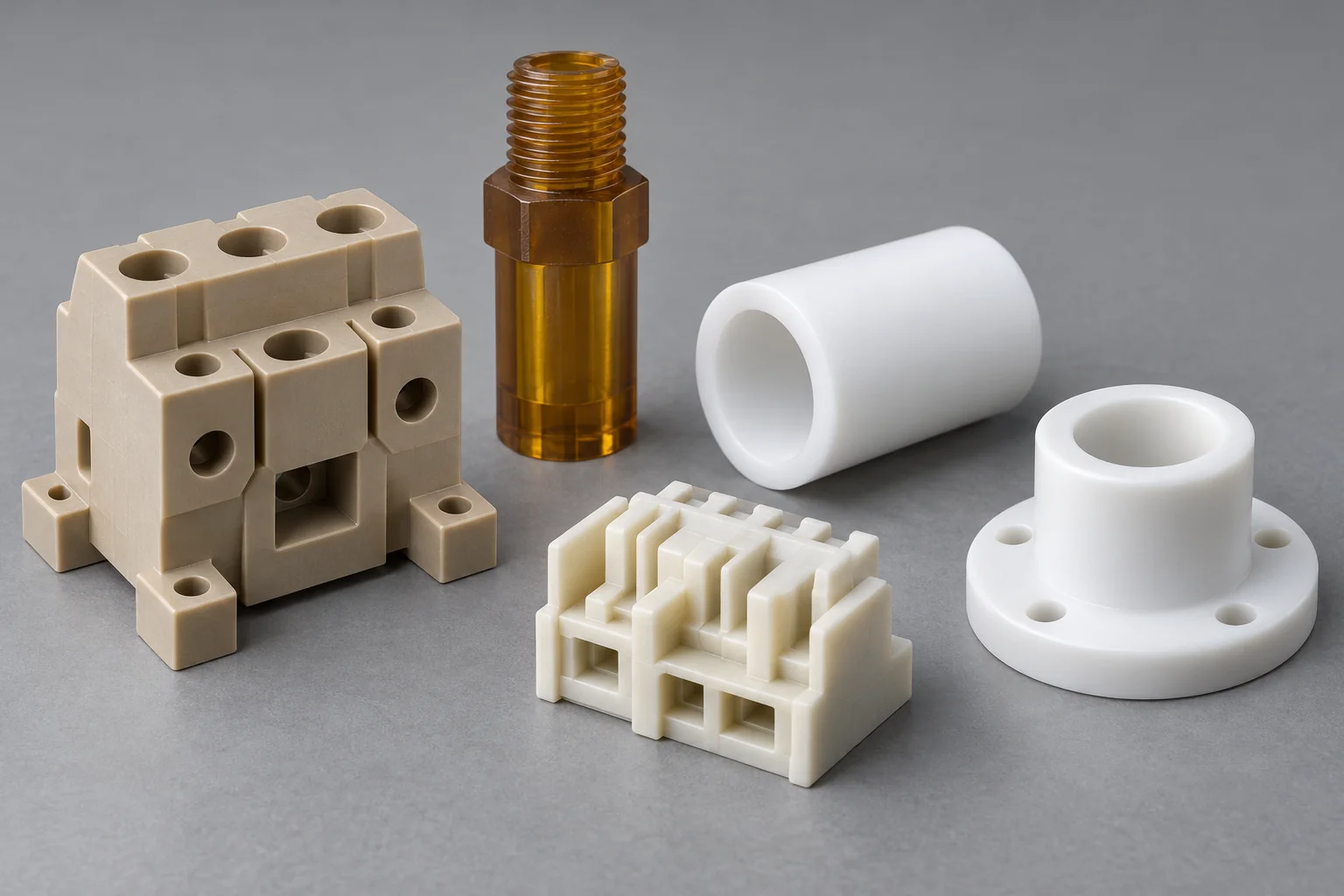
Electrical isolation and mechanical support must be defined together in the released component drawing.
| Capability | TOPS Plastics |
|---|---|
| Component types | Sleeves, blocks, spacers, bushings, housings, supports and special profiles. |
| Materials | PEEK, PEI / Ultem, PPS, PTFE, POM, Nylon and specified engineering grades. |
| Processes | CNC milling, turning, drilling, tapping and 5-axis machining where geometry justifies it. |
| Features | Holes, counterbores, threads, slots, shoulders, pockets and mounting interfaces. |
| Electrical role | Isolation, spacing, support and dielectric separation to the specified assembly design. |
| Production | Prototype, low-volume and repeat OEM production. |
| Input | CAD models, 2D drawings and reference samples with agreed dimensions. |
| Inspection | Dimensional inspection to the agreed drawing, datums and method. |
| Documentation | Project-specific material documentation where available and agreed before ordering. |
Explore the insulator geometry that matches your machine. Each component is reviewed against its electrical barrier, mounting interfaces and operating duty.
Precision sleeves electrically separate shafts, fasteners, terminals or other metal components.
Discuss this insulator →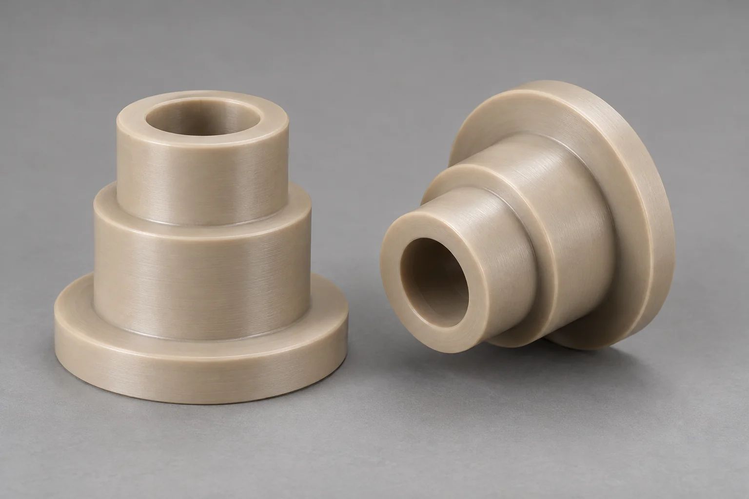
Stepped or flanged bushings combine mechanical location with electrical separation.
Discuss this insulator →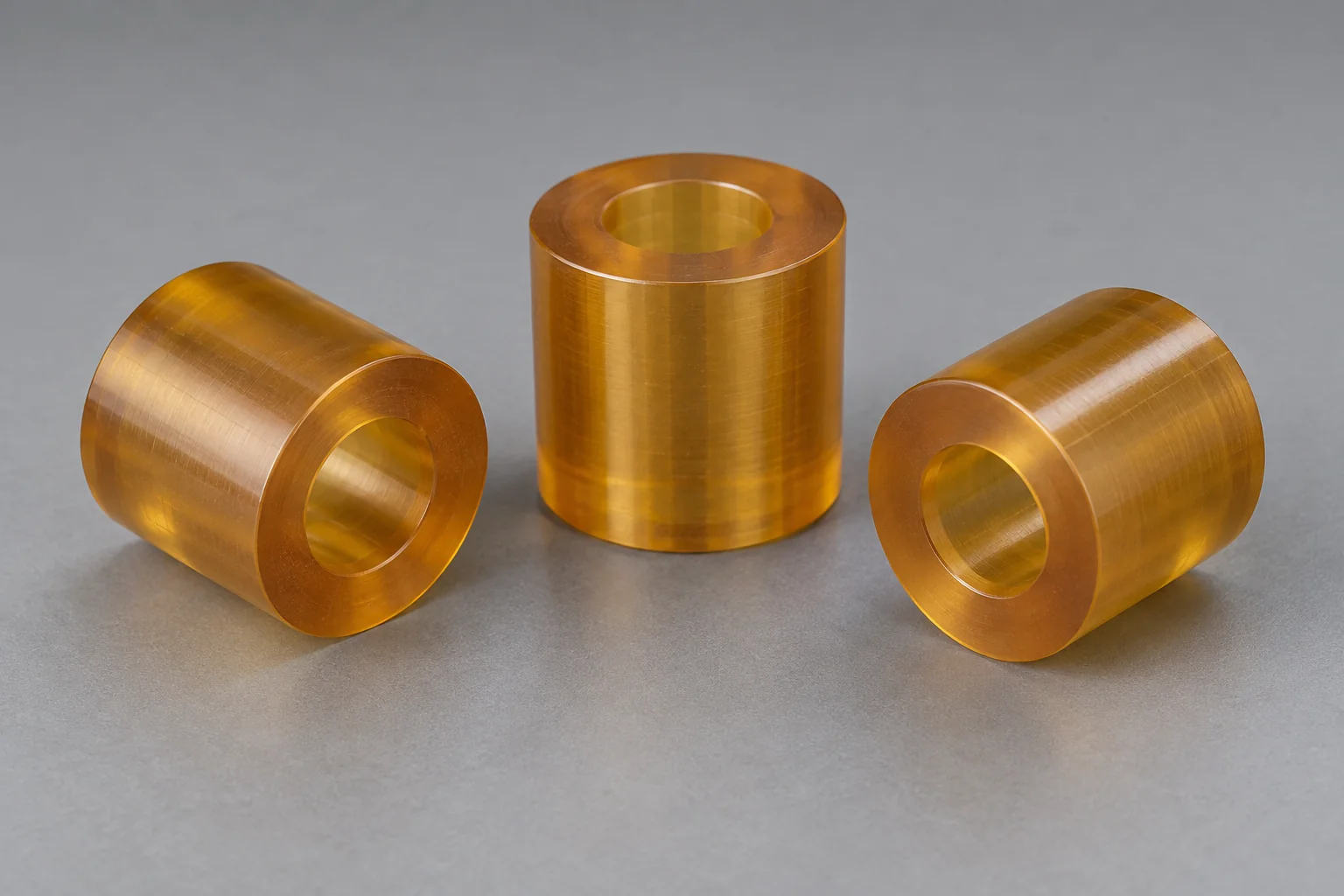
Maintain drawing-defined electrical and mechanical distance between conductive parts.
Discuss this insulator →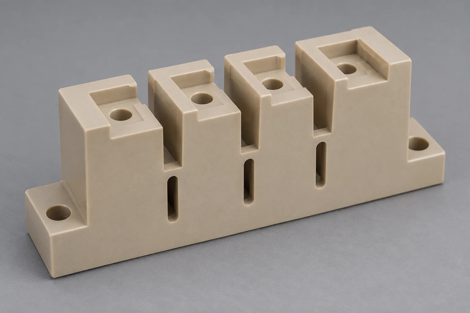
Rectangular or complex blocks support fixtures, electrical assemblies and semiconductor equipment.
Discuss this insulator →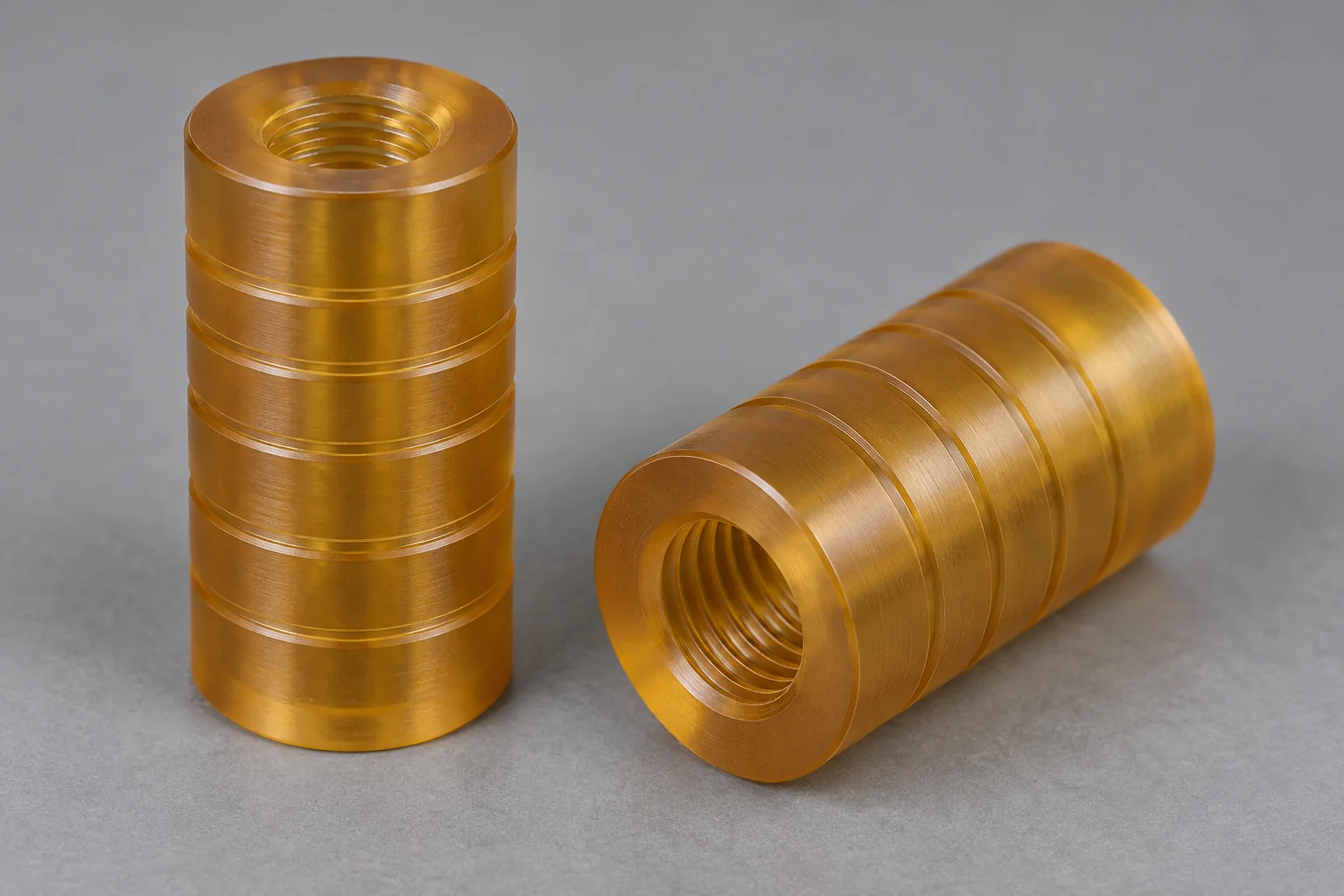
Support and separate conductive assemblies with specified mounting and insulating paths.
Discuss this insulator →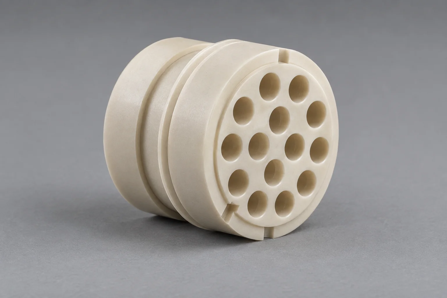
Custom connector or terminal inserts with controlled pin passages, walls and mating geometry.
Discuss this insulator →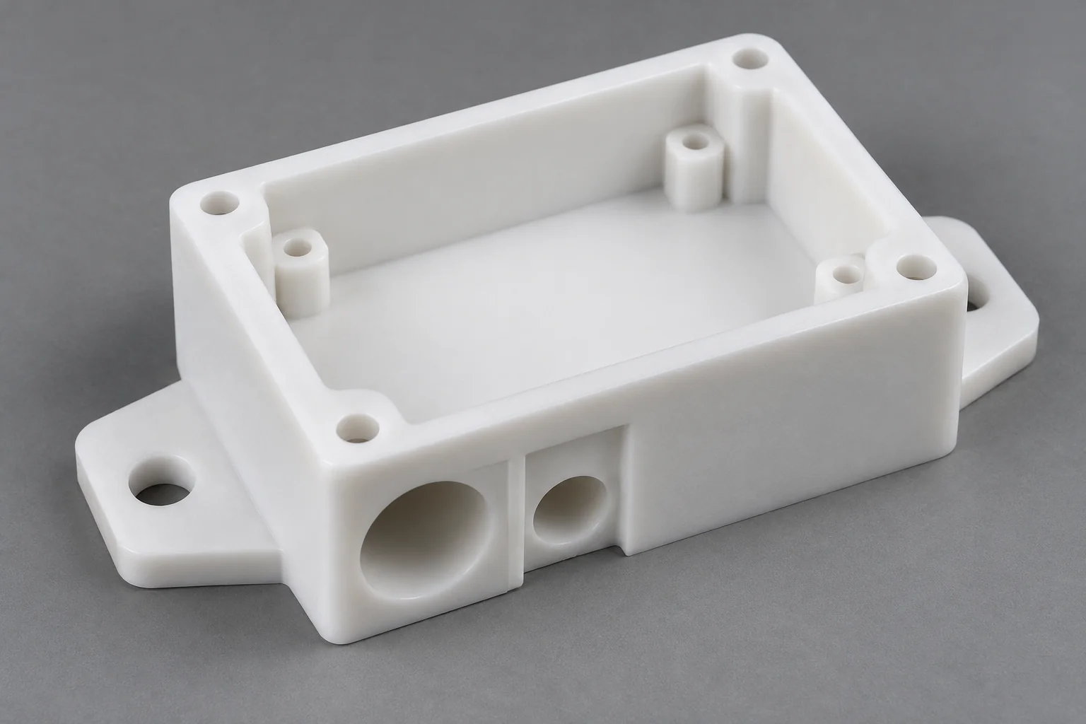
Protect and isolate sensors, electronics and electrical assemblies with defined interfaces.
Discuss this insulator →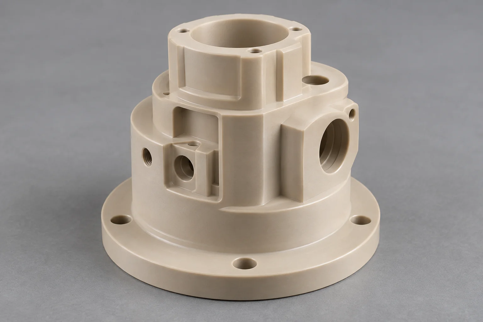
Multi-level shoulders, cutouts, slots, pockets, mounting interfaces and cable passages made to your drawing.
Discuss this insulator →Plastic insulators are non-conductive polymer components that electrically separate conductive parts while providing mechanical spacing, support, protection or alignment.
An industrial insulator often performs electrical and structural functions at the same time. Material selection must therefore consider voltage environment, temperature, mechanical load, chemical exposure and dimensions together.
Electrical isolation is the primary function on this page. Plastic spacers primarily control assembly distance; bushings primarily guide shafts or motion. Similar shapes can have different acceptance requirements.
Suitable engineering polymers combine an insulating function with custom mounting and support geometry.
Appropriate insulating grades provide dielectric separation between conductive components. Fillers and exact material designation matter.
Polymers can reduce mass compared with many ceramic or metal-isolated assemblies, depending on geometry.
CNC machining supports holes, threads, pockets, sleeves and integrated locating features.
Selected PEEK, PTFE, PPS and PVDF grades suit particular harsh environments; check the actual medium and temperature.
PEEK, PEI and PPS offer options for demanding thermal service, subject to the grade and operating conditions.
Many insulating polymers also provide useful stiffness and strength. Review creep, fastening and the sustained load.
Consider PEEK for demanding thermal and mechanical duty, PEI for electrical structures, PPS for chemical and dimensional stability, PTFE for dielectric and chemical isolation, and POM for precision lower-temperature parts.
| Material | Main strength | Main consideration | Typical use |
|---|---|---|---|
| PEEK | Thermal capability and mechanical strength. | Cost, fillers and actual electrical data. | Critical insulating supports and components. |
| PEI / Ultem | Useful heat, electrical and grade-specific flame performance. | Chemical limits, humidity and exact certification. | Electrical structures and standoffs. |
| PPS | Chemical, thermal and dimensional stability. | Brittleness and filler effects on electrical behavior. | Technical insulating blocks and inserts. |
| PTFE | Useful dielectric properties and broad chemical resistance. | Low stiffness and creep under sustained load. | Chemical-service electrical sleeves and isolation parts. |
| POM / Delrin | Low moisture uptake and dimensional control. | Lower thermal capability than high-performance grades. | Precision lower-temperature spacers and insulators. |
| Nylon | Toughness and useful mechanical support. | Moisture uptake affects dimensions and electrical behavior. | General industrial insulating components. |
| PVC | Useful electrical and chemical properties. | Operating-temperature and medium limits. | Electrical and process-equipment components. |
Select the exact supplier grade, filler content and stock form. Conductive, carbon-filled and ESD materials are not interchangeable with electrically insulating grades. Color alone does not establish electrical behavior.
FR-4 and G10 are glass-fiber laminates with different machining characteristics. They are not listed here as an established TOPS machining offering; contact us for a separate feasibility review if your drawing specifies them.
Electrical-property values must be tied to the exact grade, test method, specimen thickness and relevant conditioning.
Resistance to electrical breakdown through the material under a defined test. A data-sheet value is not a finished component voltage rating.
Resistance to current through the bulk material. Temperature, moisture and fillers can affect the result.
Resistance to current along the surface. Cleanliness, humidity and contamination are important.
Relative permittivity matters in some RF, sensor and high-frequency applications. Specify the relevant frequency and conditions.
Describes dielectric losses under specified conditions; frequency and temperature may affect heating and signal performance.
Surface tracking and arc behavior require the appropriate test data and application review. These properties are distinct from bulk dielectric strength.
Provide the electrical specification or required data-sheet properties before material approval. Generic labels such as PEEK, PEI or PTFE do not establish dielectric strength, resistivity, tracking resistance or a UL flame classification for every grade.
Clearance is the shortest distance through air between conductive parts. Creepage is the shortest path along an insulating surface. Both belong to the complete assembly design.
Conceptual paths only · not to scale · no minimum distances specified
The shortest available air path between conductive parts.
The shortest applicable insulating surface path between conductive parts.
Review working and transient voltages, altitude, insulation category, field conditions and the governing equipment standard. An air path is not the same as solid material thickness.
Review voltage, material group, pollution degree, surface geometry and the governing standard. Conductive residues and moisture can change surface behavior.
Features may lengthen an applicable surface path when the standard’s geometry rules allow it. A groove does not automatically increase the required air clearance.
Conductive edges can concentrate the local electric field; polymer corners may also concentrate mechanical stress. Review the actual conductor and insulator geometry.
Do not assign a universal creepage or clearance dimension from the polymer name or voltage alone. The responsible equipment designer must establish the applicable standard, insulation level and minimum distances; the part drawing should identify the dimensions that preserve them.
The path sketch is conceptual only. It is not to scale and does not show a standards-compliant minimum spacing or a validated voltage rating.
Service and storage conditions influence both dimensions and electrical performance.
Stiffness and dielectric behavior can change with temperature. Specify continuous, peak, cycling and inspection conditions.
Nylon and other moisture-absorbing polymers can change dimensions and electrical behavior. Agree conditioning and humidity or immersion exposure.
Cleaning agents, coolants and process media can attack an unsuitable polymer. Give chemical, concentration, exposure time and temperature.
Dust, salts, conductive residues or condensation can reduce surface insulation. Consider cleaning, handling and protection of functional surfaces.
Many insulators carry fastener preload, component weight, vibration or assembly forces. Select the polymer for electrical and mechanical requirements together.
Review supported area, local seating pressure and allowable deformation under the component weight or clamp.
Fasteners can concentrate stress and reduce a polymer stack over time. Define the assembly method and retention strategy.
A support block or standoff may deflect under an offset load. Give support span, load direction and permitted movement.
Cyclic movement may affect mounting, contact surfaces and electrical distances. Review the complete assembly duty.
Handling or operating impacts can damage brittle grades or thin sections. Consider radii and adequate support.
Sustained stress can change geometry and clamp-load retention. Short-term strength does not establish long-term performance.
Plastic-to-metal differential expansion can alter mounting stress, alignment and working distances.
A PEEK support block and a PTFE sleeve can both be insulating yet behave very differently under load. Compare the exact grade’s time- and temperature-dependent response rather than selecting by dielectric properties alone.
Prioritize the dimensions controlling insulation thickness, spacing, alignment and mating interfaces rather than tightening every cosmetic surface.
| Feature | Why it matters |
|---|---|
| Insulation thickness | Preserves the drawing-defined solid insulation barrier. |
| Bore diameter | Controls fastener or shaft isolation and fit. |
| Hole position | Maintains assembly alignment and electrical distances. |
| Spacer height | Controls clearance and stack dimensions. |
| Parallelism | Supports stable seating and predictable spacing. |
| Thread geometry | Affects retention and fastening reliability. |
| Shoulder height | Locates the electrical and mechanical interface. |
| Surface condition | May affect selected electrical interfaces and cleanliness requirements. |
State critical datums, GD&T, inspection temperature, conditioning and measurement method. Soft or thin parts can deform under gauge contact force. Dimensional conformity alone does not establish electrical compliance or a voltage rating.
Define the electrical function and assembly constraints before releasing the manufacturing drawing.
Provide voltage, AC / DC, creepage, clearance and the governing standard or equipment specification.
Electrical behavior and flame performance are grade-specific. Identify supplier designation and fillers.
Let the application’s electrical requirements determine the solid barrier and inspection dimensions.
Use suitable transitions around holes, shoulders and cutouts, especially in brittle or glass-filled polymers.
Review bolts, clamps, seating areas and thread engagement alongside the insulating path.
Account for differential movement and stress in plastic-to-metal assemblies.
Specify conditioning and exposure, particularly where Nylon is considered.
Mark the faces controlling stack height, mounting and conductor separation.
The machining route follows the functional barrier, electrical spacing and mounting geometry.
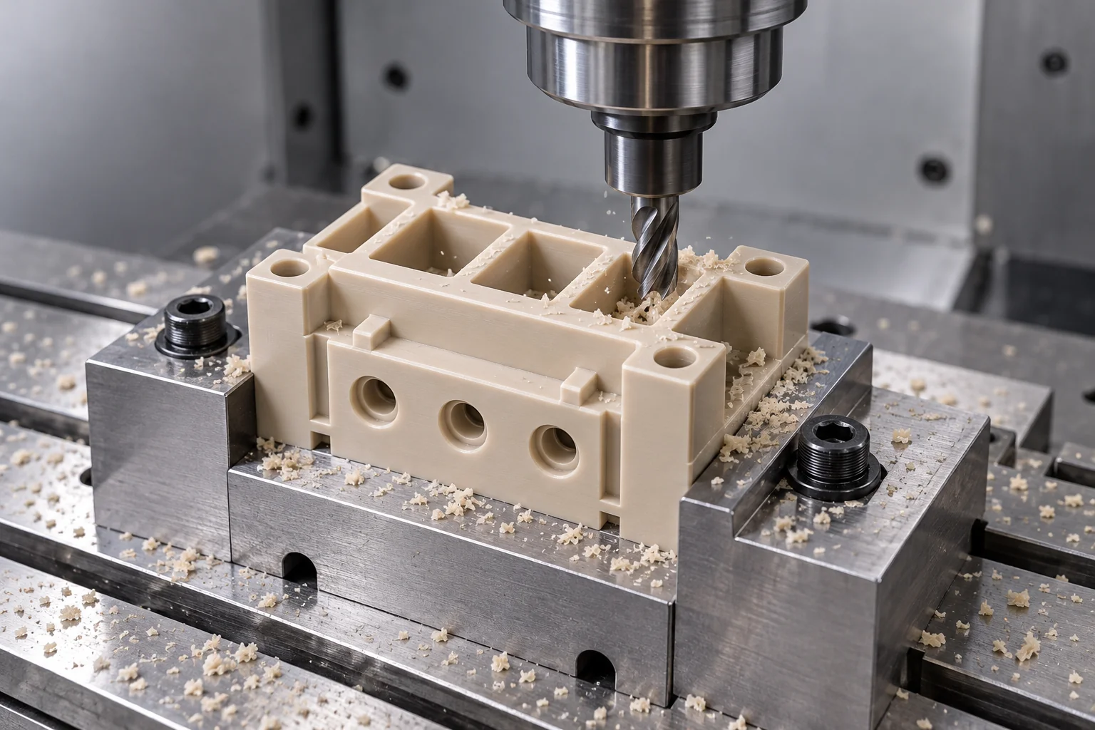
Creates insulating blocks, plates, housings, fixtures, pockets and complex cutouts.
Produces sleeves, bushings, standoffs and cylindrical insulating components.
Supports suitable complex multi-face geometry; tool access and local support must still be reviewed.
Creates mounting holes and thread interfaces with adequate wall thickness and engagement.
Removes unwanted burrs around holes, slots and insulating paths. Agree any application-specific cleaning and packaging requirements.
Checks critical spacing, bores, thickness, hole positions and overall geometry to the agreed drawing.
Engineering plastics suit many custom geometry requirements; ceramic remains valuable for different thermal, electrical and mechanical duties.
| Factor | Engineering plastic | Ceramic |
|---|---|---|
| Machinability | Useful for custom CNC features and smaller orders. | Often requires more specialized machining and processing. |
| Weight | Often lower for similar geometry. | Often higher; composition and geometry matter. |
| Impact toughness | Many grades tolerate impact better than brittle ceramics. | Many electrical ceramics are brittle. |
| Extreme temperature | More limited by polymer and grade. | Suitable ceramics can support much higher temperatures. |
| Electrical insulation | Grade-, geometry- and environment-dependent. | Composition-, geometry- and environment-dependent. |
| Complex threads / features | Often easier to machine in suitable grades. | Can be more difficult or require specialized methods. |
| Chemical resistance | Depends on polymer, stress and medium. | Often useful, but composition and medium must be checked. |
| Prototype / custom parts | Strong option for many drawing-based components. | A more specialized route for particular requirements. |
Consider plastic where complex features, low mass, toughness and CNC customization matter. Consider ceramic for extreme temperatures, ceramic-specific electrical requirements or governing specifications. Validate any substitution at the assembly level.
Metal-isolated designs use a conductive structural part plus a separate insulating barrier. Review every parallel leakage path, fastener and interface; a polymer part should not replace that system solely because the envelope matches.
Examples guide the discussion. Exact-grade suitability, cleanliness and any regulatory requirements are project-specific.
PEEK, PPS, PEI and PTFE fixtures, isolation blocks and supports with defined electrical and process requirements.
Connector inserts, insulating spacers, terminal parts and housings.
Sensor isolation, motor-related mounting components and insulating supports.
Fixture insulators and high-voltage test components manufactured to the released electrical design.
Electrical and mechanical isolation components where documented grades suit the application.
Motor, sensor and actuator insulation components.
Chemical-resistant insulating parts matched to the actual media and cleaning regime.
The dimensional inspection plan follows the electrical barrier, critical spacing and mounting datums.
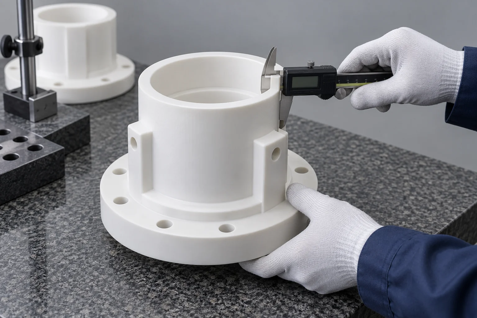
Check the exact polymer, fillers, supplier designation and agreed documentation.
Identify the specified barrier, creepage, clearance and controlling dimensions.
Measure functional wall or barrier thickness with appropriate support and contact force.
Check mounting and conductor interfaces against the required datums.
Verify seating faces and the dimensions preserving the assembly separation.
Check designated threads, shoulders, slots and retention features.
Inspect surfaces and edges for unwanted burrs, damage and agreed cleanliness.
Confirm the certificates or material records available and included in the order.
Protect functional surfaces, identify the drawing revision and meet agreed handling requirements.
Dielectric withstand, insulation-resistance or other electrical testing is a separate acceptance requirement. If required, agree the test method, voltage, duration, conditioning and a verified test provider before ordering. It is not implied by the dimensional inspection described here.
Approve the geometry, material and acceptance plan before repeating the production specification.
Validate fit, working distances, material and assembly geometry. Electrical acceptance follows the agreed project test plan.
CNC manufacture supports specialized components without dedicated molding tools.
Maintain the exact grade, released drawing, machining program and inspection requirements.
A plastic insulator must satisfy electrical and mechanical requirements. Grade, insulation thickness, creepage and clearance, temperature, load and dimensional accuracy should be reviewed together before manufacturing.
Custom insulating geometry reviewed against your CAD model and functional drawing.
Grade choices considered against electrical, thermal and chemical conditions.
The process follows the component geometry and access requirements.
The insulating role is considered alongside load, mounting and material response.
The drawing identifies barriers, working distances and controlling tolerances.
Initial validation leads to a defined recurring manufacturing specification.
Required and available documentation is agreed before the order.
Associated mounting and assembly requirements can be reviewed where specified.
Practical answers for specifying, selecting and sourcing custom polymer insulators.
Plastic insulators electrically separate conductive parts while supporting, locating or protecting them. Common industrial uses include terminal blocks, connector inserts, sleeves, standoffs and equipment fixtures.
There is no universal best polymer. Select the exact grade against electrical data, voltage environment, temperature, load, moisture and chemicals. PEEK, PEI, PPS and PTFE offer different balances of properties.
Suitable PEEK grades can provide useful electrical insulation with demanding thermal and mechanical performance. Conductive or carbon-filled grades may behave differently; confirm exact-grade data and the component design.
Clearance is the shortest air distance between conductive parts; creepage is the shortest path along an insulating surface. Required distances depend on the governing standard, voltage and application conditions.
PTFE suits many chemical environments, but the exact medium, temperature and exposure must be reviewed. Its low stiffness and creep also matter where the part carries mechanical load.
Suitable PEI grades are often considered for heated electrical structures. Verify the exact grade’s temperature, dielectric and flame data along with chemical compatibility, moisture and mechanical load.
Yes, drawing-defined threads can be reviewed for machining. Engagement, wall thickness, polymer strength, creep and the full electrical path must be considered with the mating hardware.
Insulation thickness, spacing, hole position, stack height and mating interfaces usually control function. Define the datums and inspection state; electrical acceptance is separate from dimensional conformity.
Sometimes, where the complete thermal, electrical and mechanical requirements permit it. Plastic offers CNC customization and toughness, while suitable ceramics may be needed for extreme heat or ceramic-specific specifications. Validate the assembly before substitution.
Yes, we can review CAD models and drawings for custom insulator manufacture. Include the exact grade, electrical specification, voltage, minimum working distances, temperature, mechanical loading and documentation requirements.
YOUR ELECTRICAL REQUIREMENT. YOUR EXACT GRADE.
Upload your insulator drawing or CAD model and specify the material, quantity, electrical requirements, operating voltage, critical dimensions, temperature, chemical exposure and mechanical loading. TOPS Plastics can review the geometry and material requirements before quotation.
Company, name, email and phone are required. Country, part number, quantity and drawing upload are optional. Include the electrical and engineering specification in your drawing package or email to keep the form short.
info@tops-precision.comSTEP / STP / IGES / X_T / DWG / DXF / PDF or ZIP, maximum 10 MB. Larger packages can be shared by email. Agree confidential-file handling before sending sensitive drawings.