01
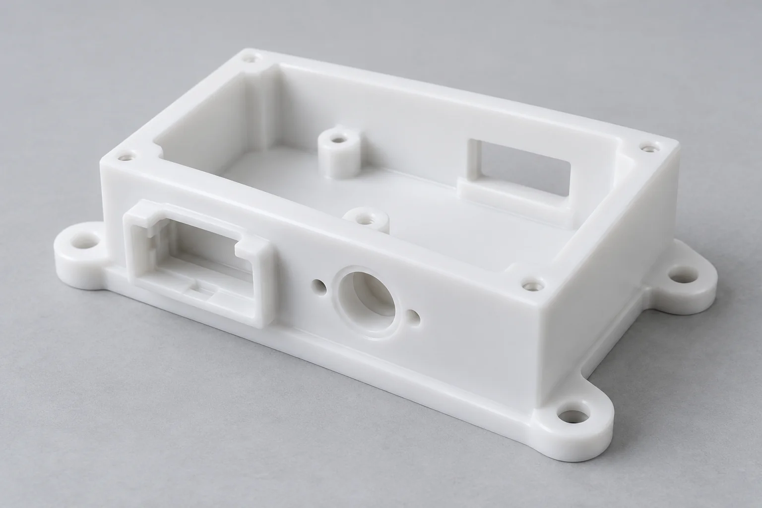
Plastic Housings
Sensor, diagnostic, electronics and instrument bodies with cavities, connector openings and mounting interfaces. Define stiffness, finish and assembly requirements.
Explore component details →
PRECISION COMPONENTS · MEDICAL EQUIPMENT
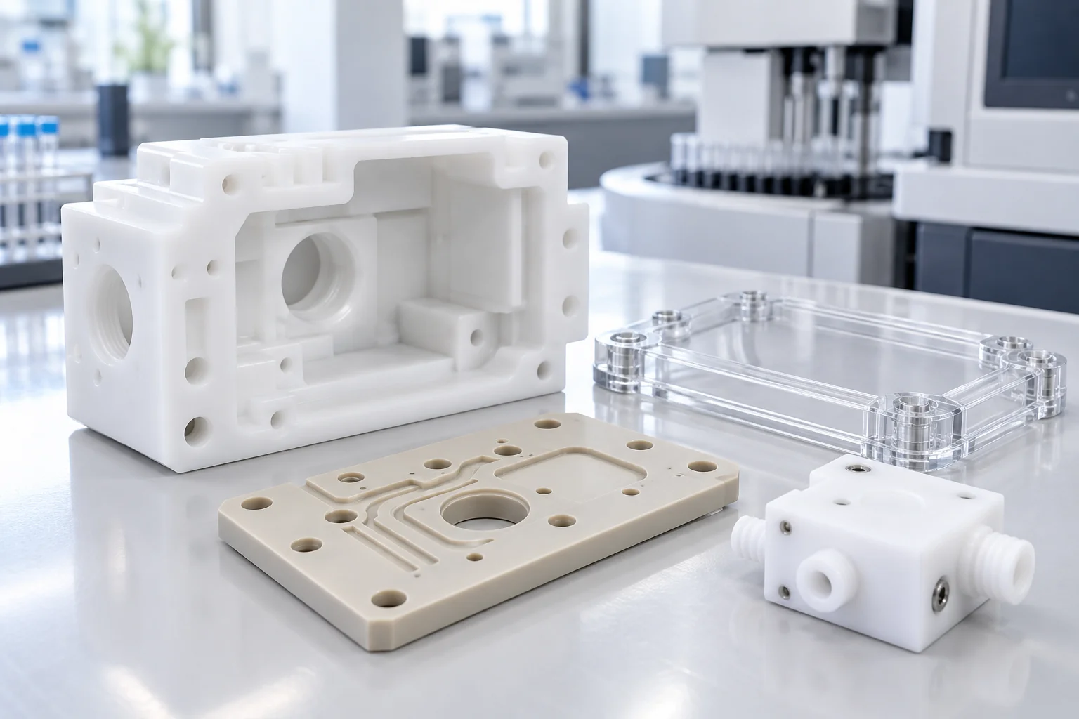
TOPS Plastics manufactures custom CNC machined plastic components for medical devices, diagnostic systems, laboratory equipment, surgical instruments, fluid-handling systems and precision medical assemblies. We machine PEEK, POM, PTFE, PEI, PPS, Polycarbonate and other engineering plastics according to customer drawings, material specifications and application requirements.
Define the component function, material grade and acceptance requirements before choosing a machining route.
| Capability | TOPS Plastics |
|---|---|
| Typical parts | Housings, manifolds, insulators, spacers, fixtures and rollers |
| Materials | PEEK, POM, PTFE, PEI, PPS, Polycarbonate, Acrylic and specified grades |
| Processes | CNC milling, turning, 5-axis machining, drilling and tapping |
| Key requirements | Precision, cleanliness, compatibility and documentation |
| Production | Prototype, low-volume and repeat production |
| Input | STEP, 3D CAD, 2D drawings and reference samples |
| Inspection | Drawing-based dimensional inspection of agreed features |
| Documentation | Material and inspection documents where specified, agreed and available |
Explore equipment components by function. Define the exact grade, mating interfaces, cleaning exposure and acceptance requirements with the drawing.
Sensor, diagnostic, electronics and instrument bodies with cavities, connector openings and mounting interfaces. Define stiffness, finish and assembly requirements.
Explore component details →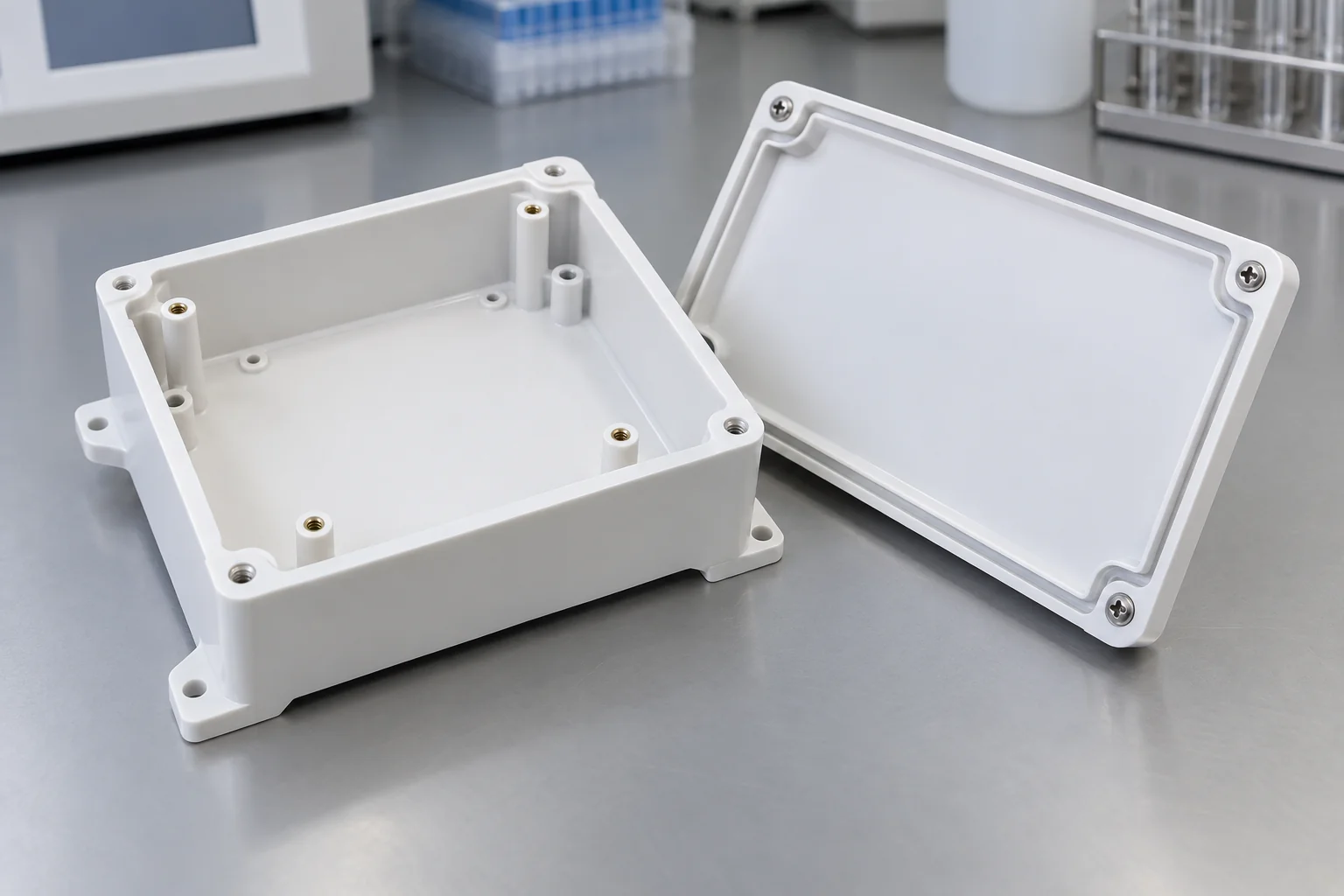
Protective bodies for medical electronics, laboratory analyzers and monitoring systems. Specify access, sealing interfaces and any transparent areas.
Explore component details →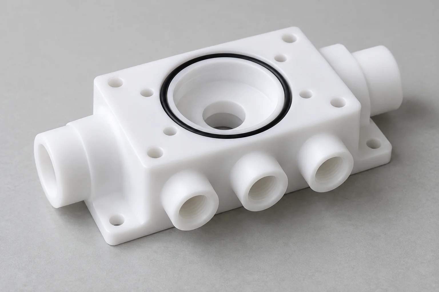
Fluid routing, reagent distribution, pneumatic control and liquid-handling blocks. Identify wetted surfaces, port standards, seals and internal inspection needs.
Explore component details →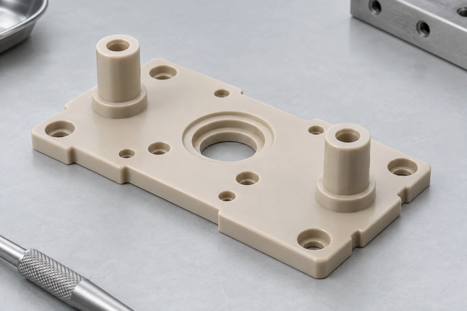
Electrical isolation, sensor supports and equipment spacing. Select a documented grade for the actual voltage, temperature and environmental requirements.
Explore component details →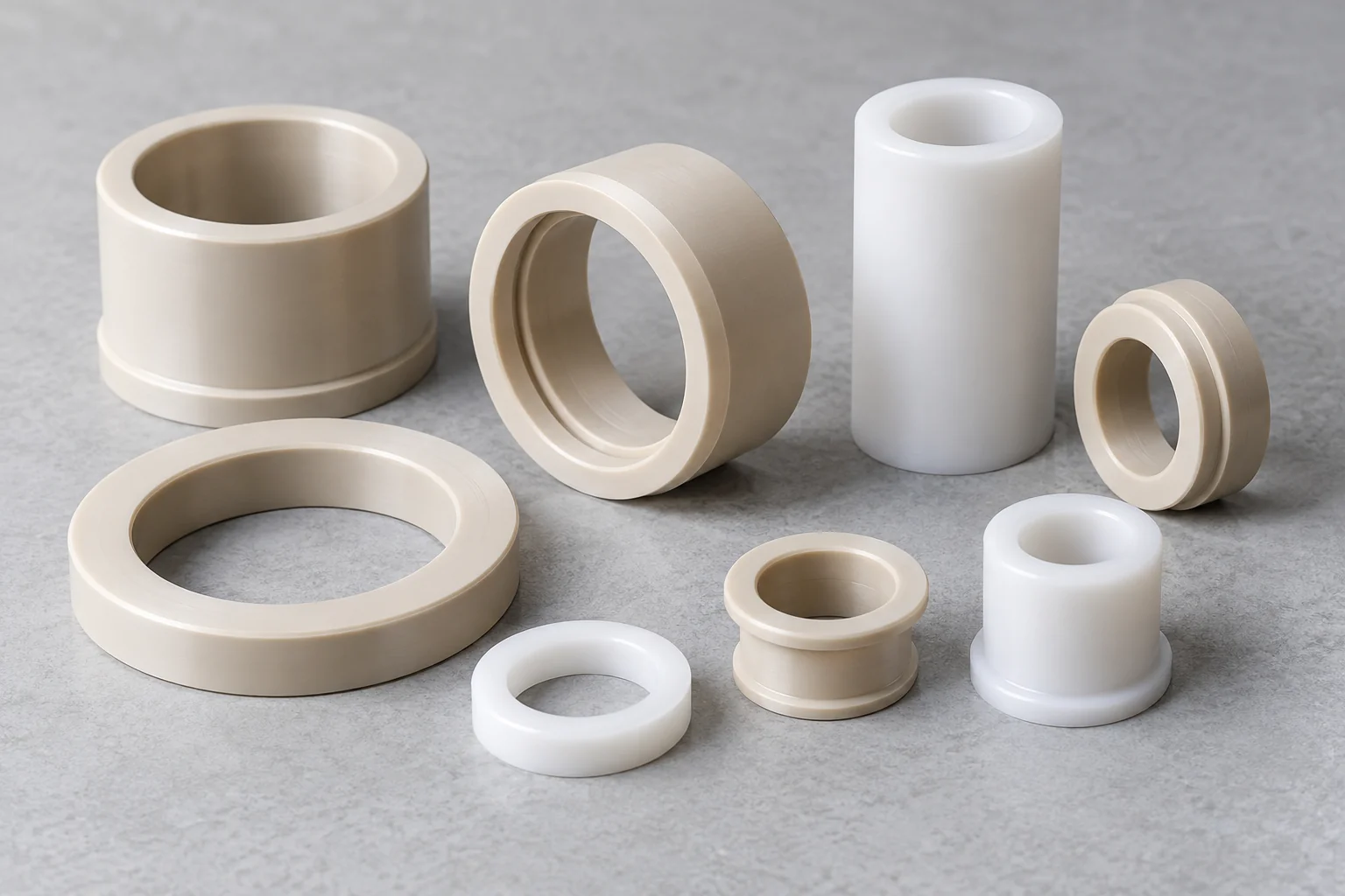
Assembly spacing, electrical separation and precision stack control. Define thickness, parallelism, bore fit and retained loading.
Explore component details →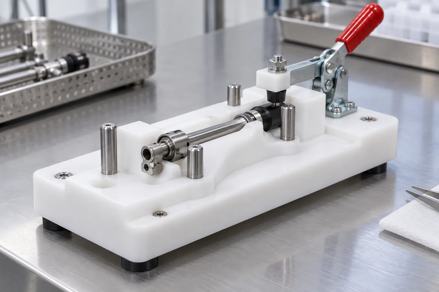
Assembly, testing, inspection and diagnostic-equipment production tooling. Establish datums, contact zones, clamp loads and repeatability criteria.
Explore component details →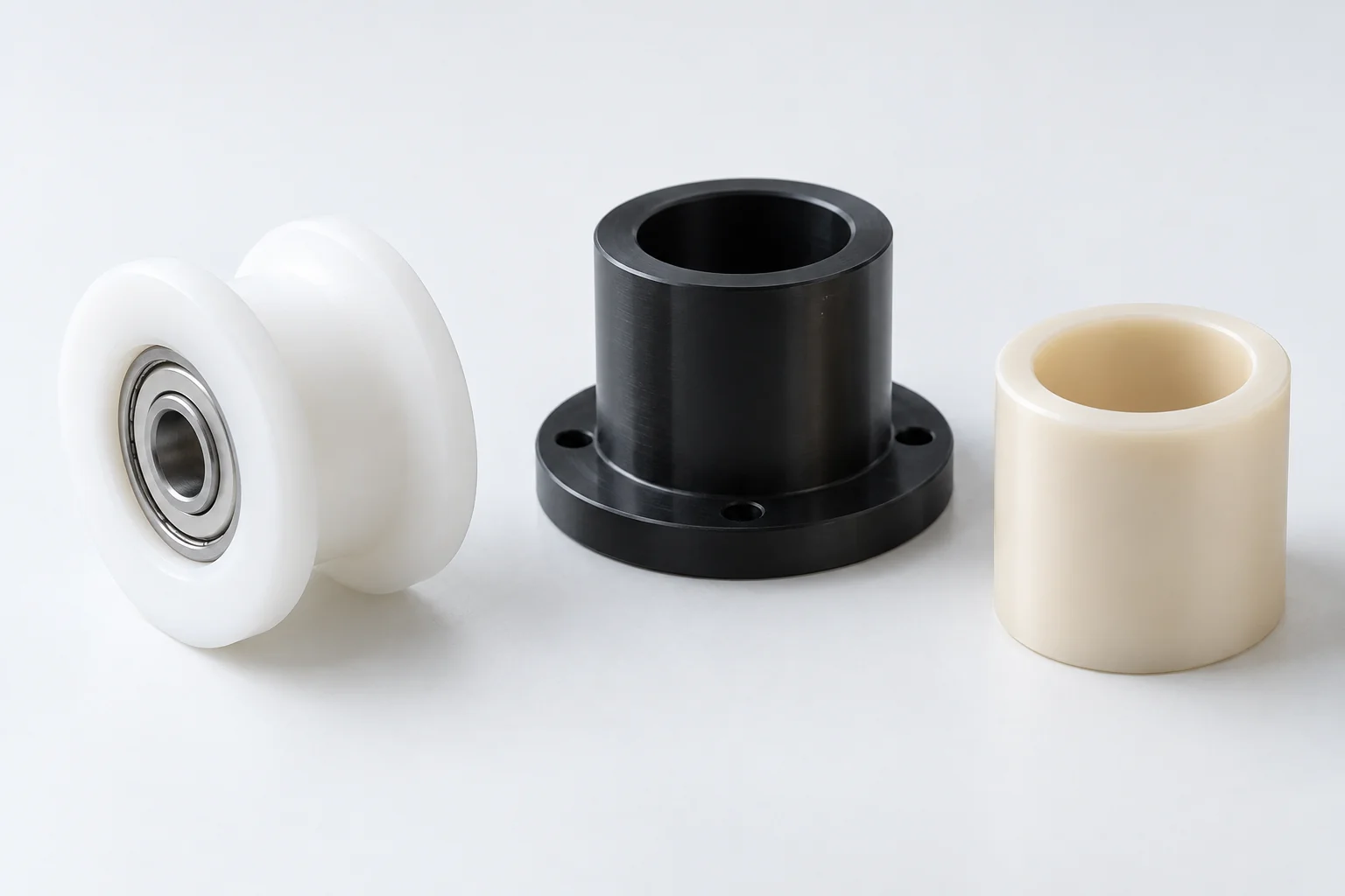
Guided motion in pumps, analyzers and automated equipment. Review speed, load, clearance, wear and the mating surface.
Explore component details →Plastic Bushings →Plastic Rollers →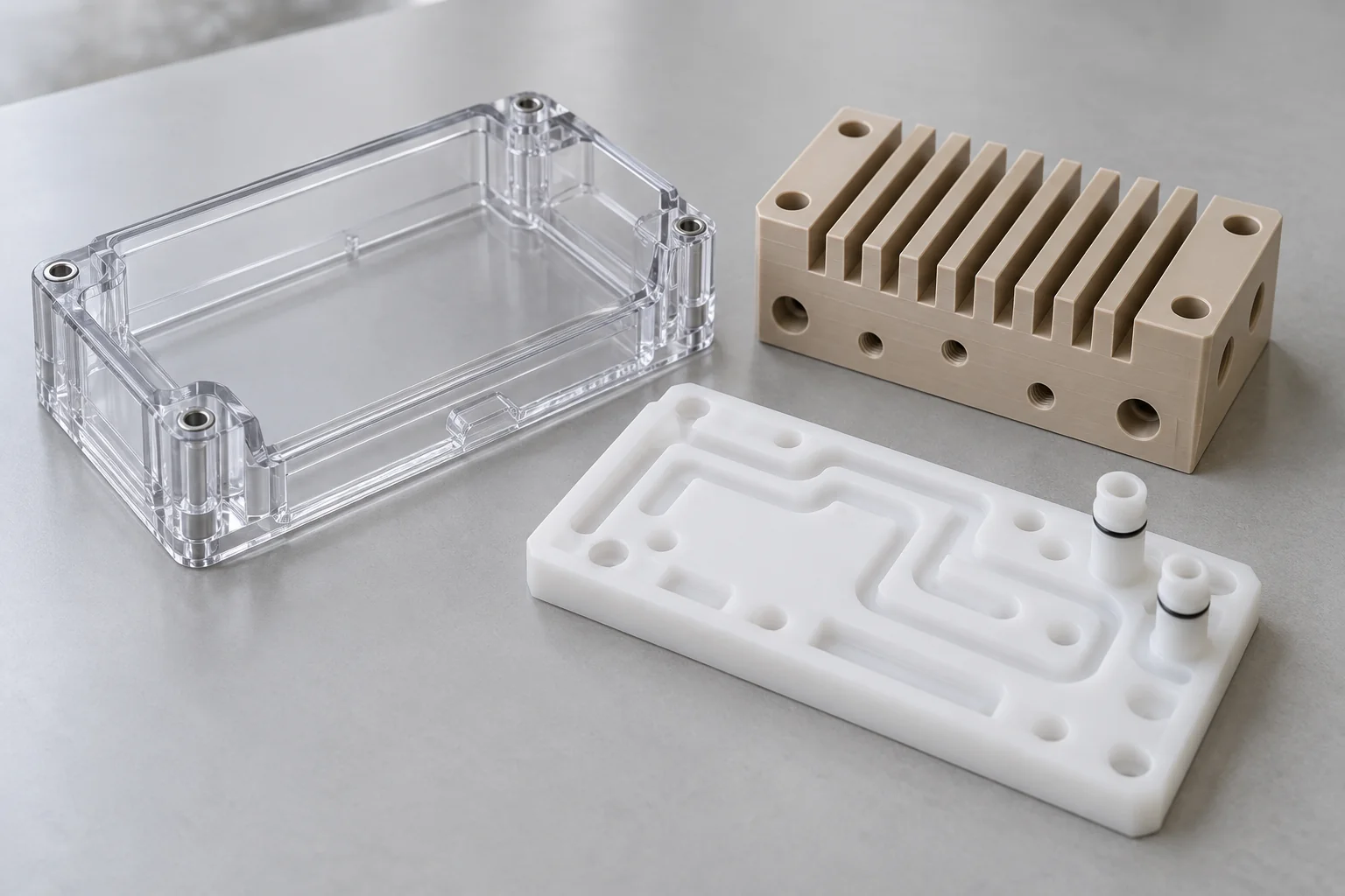
Nonstandard drawing-based components, including precision blocks, guides, plates and transparent interfaces for equipment assemblies.
Explore component details →The same polymer can perform differently across equipment applications. Begin with contact type, mechanical duty, temperature and the cleaning or sterilization process.
Housings, fluid manifolds, sensor mounts, reagent blocks, fixtures and precision spacers. Review dimensional accuracy, chemical resistance, cleanliness and assembly repeatability.
Transparent covers, racks, instrument housings, fluid-routing parts and fixtures. Chemical compatibility, optical needs and dimensional stability guide selection.
Potential handles, insulators, guides, structural components and instrument fixtures. Specify load, surface condition, sterilization exposure and required material evidence.
Electronics housings, connector supports, insulators, spacers and sensor interfaces. Define electrical properties, contact classification and environmental exposure.
Manifolds, valve blocks, pump parts, fittings and sealing interfaces. Define fluids, pressure, temperature, cleaning and seal geometry.
Bearings, bushings, rollers, guides, fixtures and structural housings. Loading, duty cycle, wear and repeatable positioning shape the design.
There is no single best plastic. PEEK, POM, PTFE and transparent polymers serve different functions; the actual resin grade and required documentation control suitability.
| Material | Main advantage | Application direction | Review before selection |
|---|---|---|---|
| PEEK | Strength, heat and chemical performance | Precision structural components | Exact grade, load, sterilization exposure and contact requirements |
| POM / Delrin | Machinability and dimensional stability | Mechanical housings, guides and fixtures | Chemical exposure, temperature and documented grade |
| PTFE | Low friction and broad chemical resistance | Fluid, sealing and sliding components | Creep, stiffness and sealing geometry |
| PEI / Ultem | Thermal and electrical performance | Insulators, electronics and instrument parts | Cleaning chemicals and grade-specific electrical data |
| PPS | Dimensional and chemical performance | Technical components | Brittleness, fillers and operating environment |
| Polycarbonate | Toughness and transparency | Covers, housings and guards | Chemical stress cracking, finish and cleaning exposure |
| Acrylic / PMMA | Optical clarity | Observation and instrument windows | Impact, solvent sensitivity and optical acceptance |
| UHMW | Wear resistance and low friction | Guides and wear components | Lower rigidity and creep under sustained load |
A polymer family is not automatically medical grade. PEEK may suit demanding structural or thermal duties, POM precision mechanical parts, PTFE compatible low-friction interfaces, and Polycarbonate or Acrylic transparent components. Confirm the specific formulation and evidence for the intended use.
Reagent manifolds, analyzer housings, sample-handling fixtures, transparent covers, sensor supports, flow blocks, mounting plates, spacers and guides connect fluid, optical and mechanical functions.

Define media, concentration, seals and passage geometry. Provide cleaning requirements and inspection access for hidden intersections.
Fixtures and guides should locate consistently without forcing the sample carrier or trapping debris. Establish contact zones and loading clearances.
Cavities, connector openings and mounting patterns must align with mating parts. Identify datum relationships rather than tightening every surface.
Specify clarity, haze, scratches and permitted machining marks. Transparency does not establish optical performance without an acceptance method.
Share the normal process conditions and the full cleaning sequence. Chemical residues, contamination, optical clarity and repeatability can interact; a finish or material chosen for appearance may not survive the required cleaning agents.
Drawing-based handles, spacers, insulators, instrument housings, guide components, precision blocks and fixtures can be reviewed for machining and material feasibility.
Provide applied load, retention details and repeated-use expectations. Identify structural areas, thin sections and interfaces that must remain stable.
State the method, temperature, chemicals and cycle count. Repeated exposure can change dimensions, toughness or appearance.
Define edges, grip areas, sealing faces and accessible cleaning surfaces. Deburring must preserve functional geometry.
Specify contact type, duration and required documentation. Resin information and machining inspection do not replace finished-device evaluation.
Customer-specified instrument components require a project-specific review. This page concerns equipment and drawing-based component manufacturing; any special patient-contact or regulatory requirements must be identified and confirmed before an order is accepted.
Manifolds, valve blocks, pump housings, tubing interfaces, sensor blocks, fluid-routing plates and sealing components should be designed around the entire wetted system.
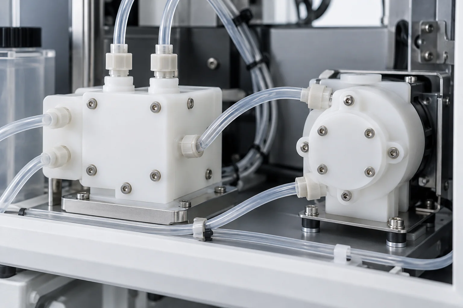
Identify the exact fluid, reagents and cleaning agents, including concentration ranges and intermittent exposures.
Provide operating pressure, temperature, flow rate and duty cycle. Define any required pressure, leak or flow test separately.
Specify O-ring grooves, port standards, tubing connections and mating parts. Surface finish, edge condition and flatness may control sealing.
State sterilization, cleaning and required contact documentation. Review the actual grade rather than relying only on a polymer name.
Chemical resistance alone does not establish compatibility for a medical fluid pathway. Required extractables, biological evaluation, residue limits or cleanliness evidence must be identified by the customer and agreed for the specific component scope.
PEEK, PEI / Ultem, PPS, PTFE and POM may be considered for insulators, spacers, connector supports, sensor housings, PCB supports and equipment blocks.
Define voltage, spacing, dielectric requirements and applicable test conditions for the complete assembly. Metal inserts and fasteners also affect isolation.
Control positioning, bore fit and mounting geometry so the sensing or connection interface remains repeatable.
Tie electrical and flame performance to the exact resin grade and applicable data. Do not transfer a rating between different formulations.
Include cleaners, disinfectants, adhesives and assembly loads. A grade suitable electrically may still need a chemical or mechanical review.
Compatibility depends on the exact grade, method, temperature, dose or chemistry and number of cycles. Repeated exposure can change color, toughness, dimensions and mechanical properties.
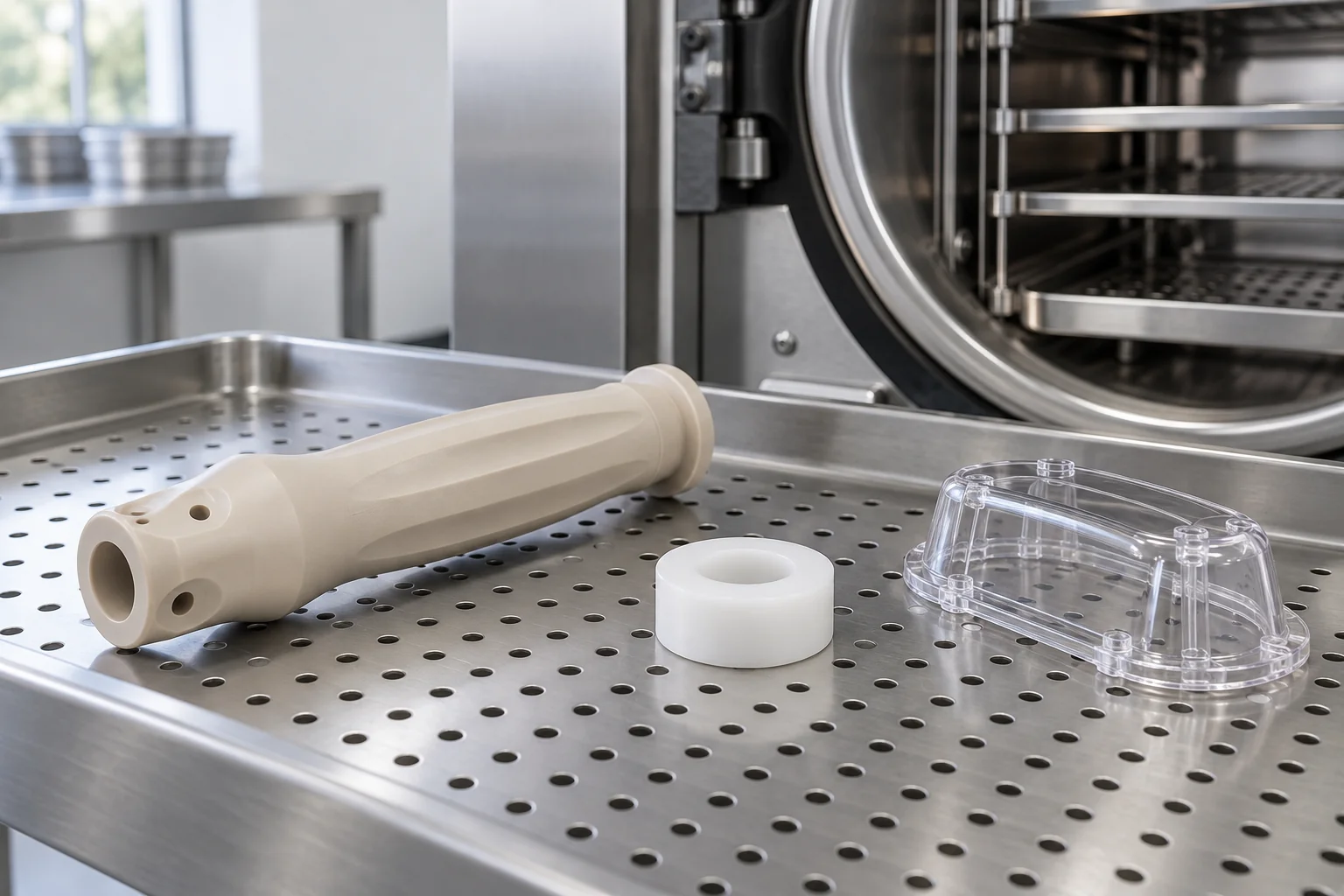
Heat and moisture challenge dimensional stability and retained properties. Specify cycle temperature, pressure, duration, drying and repeated-cycle count.
Ethylene oxide processing requires review of the complete specified cycle and material behavior. Residuals and device validation are separate acceptance considerations.
Radiation dose and cumulative exposure can affect color and mechanical properties. Compare grade-specific data at the required dose.
Electron-beam exposure also requires dose- and grade-specific evidence, including performance after the intended storage and use period.
Specify alcohols, peroxides, oxidizers or cleaners with concentration, contact time and temperature. Check stress cracking and repeated exposure.
| Requirement | Material selection consideration |
|---|---|
| Autoclave | Heat and moisture resistance at the specified cycle |
| Chemical cleaning | Compatibility with actual concentration and contact time |
| Gamma / E-beam | Radiation stability at the required cumulative dose |
| Repeated cycles | Retained function, toughness and dimensions over service life |
| Optical clarity | Color, haze and surface condition after exposure |
| Tight tolerance | Dimensional change and inspection state after conditioning |
A material data sheet is a screening input, not a guarantee that a complete component withstands every sterilization method. Review representative finished parts and agree acceptance criteria for function, dimensions and appearance after the specified exposure.
Medical grade is not a universal property of a polymer family. It generally describes a specific formulation with documented characteristics relevant to a defined medical application.
Identify manufacturer, grade, fillers, colorants and additives. Substitutions should be reviewed against the approved specification.
Specify the contact type and duration, and the ISO 10993-related evidence needed. Material data does not automatically establish finished-device biocompatibility.
Request the actual supplier documentation and its scope where required. It should not be treated as blanket approval for every device or contact condition.
Define the particular document or requirement. A general FDA-related statement is not an approval of a manufacturer, material family or finished device.
State required lot identification, documentation retention and formulation or supplier change controls so support can be confirmed.
The device manufacturer determines the applicable evaluation and acceptance requirements for the intended use. Final materials, processing residues, cleaning and sterilization can affect the finished device. TOPS Plastics can review customer-specified material and documentation requirements during quotation.
Functional dimensions must be maintained in materials that respond to heat, clamping pressure, moisture and internal stress. A material-aware process and measurement state are essential.
Plastic dimensions vary more with temperature than many metals. Define inspection and service temperatures for fit-critical features.
Some grades, particularly Nylon, change with moisture. Identify the intended conditioning state before assigning a close fit.
Clamps, cutting forces and assembly loads can deform housings or delicate sections. Provide support and avoid unnecessary local loads.
Tool access, heat and chip removal influence finish and accuracy. Review depth, corner radii and access early.
Inserted bearings, pins or hardware can distort bores and housings. Specify retained fit and allowable assembly force.
Heavy material removal can release stock stress. Review stock condition, geometry and machining sequence.
Burrs, loose chips and damaged sealing faces can affect fluid flow, assembly, cleanliness and function. Treat these as manufacturing requirements rather than cosmetic details.
Define burr condition at intersecting holes, passage entrances and port threads. Plan access for inspection and cleaning before releasing CAD.
Specify finish, flatness, edge condition and scratch limits where they control leakage, friction or assembly.
Identify required edge breaks without removing functional lands or weakening thin features. Protect finished faces during handling.
Agree clarity and appearance requirements separately from dimensional accuracy. Machining, polishing and cleaning can affect visible finish.
Customer cleanliness and packaging specifications can be reviewed for feasibility. Cleaning, residue verification, sterile supply and process validation are separate scopes that must be defined and agreed; dimensional machining alone does not establish them.
Use tight limits where function requires them. Prioritize sealing, positioning and mating relationships instead of applying the same close tolerance to every external dimension.
| Feature | Why it matters |
|---|---|
| Bore diameter | Shaft, bearing or insert fit |
| Hole position | Assembly alignment and locating |
| Flatness | Sealing and instrument stability |
| Parallelism | Fixture or stack accuracy |
| Manifold port position | Fluid-system interfaces |
| O-ring groove | Seal geometry and compression |
| Spacer thickness | Assembly stack and clearance |
| Housing interface | Component fit and mounting |
| Optical surface | Visual or sensor performance |
Realistic limits depend on grade, size, wall thickness, support, temperature and measurement method. Specify GD&T, critical datums and the free or restrained inspection state. Discuss functional validation after assembly or sterilization where it affects acceptance.
Provide the required evidence with the RFQ. Scope, availability and acceptance criteria must be confirmed for the specific order.
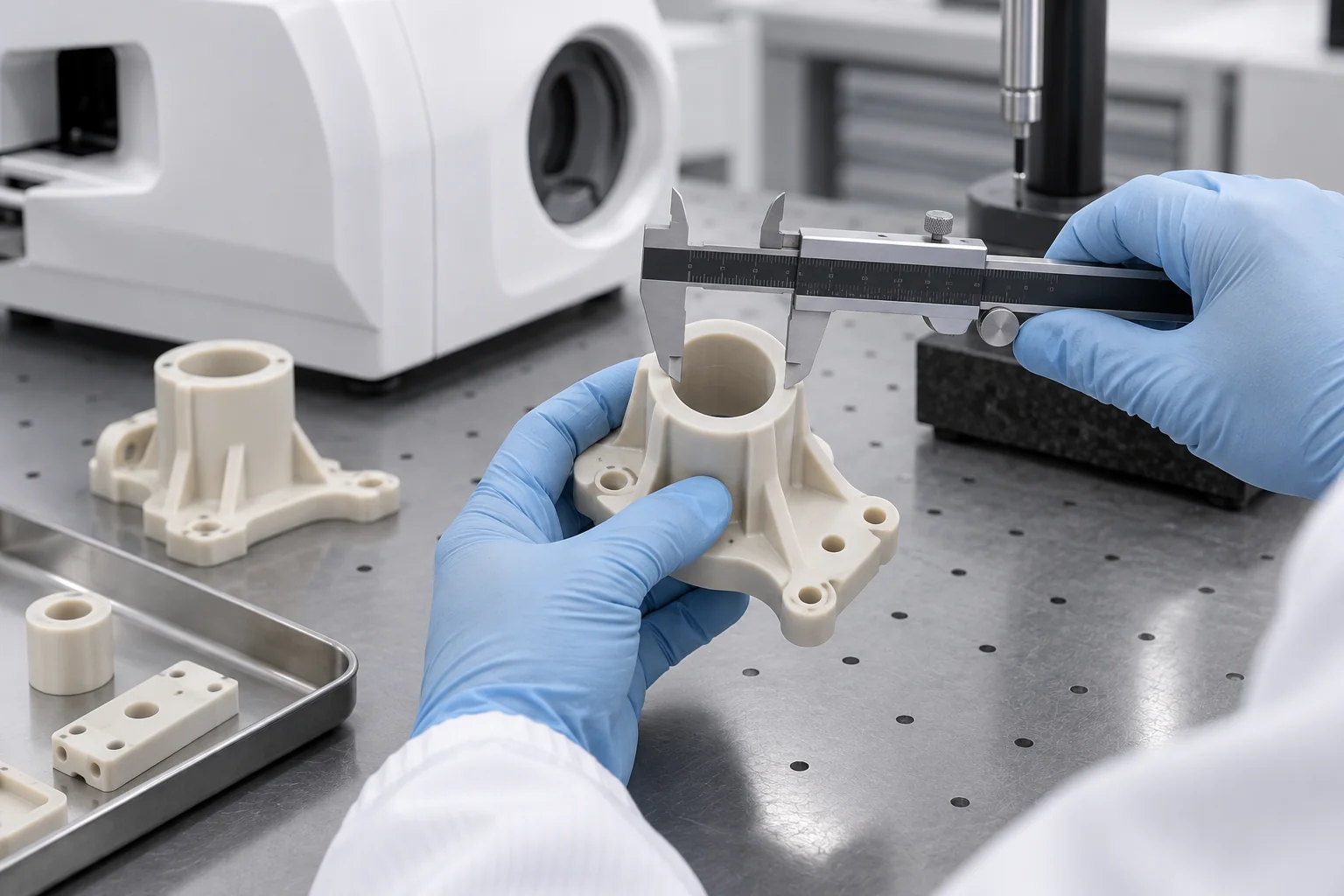
Request exact-grade certificates or supplier documents where specified and available. State the document and formulation requirements before material purchase.
Request the first-article sample quantity, critical features and report format where needed. Confirm the agreed inspection scope before manufacture.
Identify reportable features, datums, sampling and measurement conditions. Special functional or cleanliness tests require a separately agreed scope.
Use released CAD and drawings with a consistent revision across purchasing, machining and inspection. Review changes before repeat production.
State required material-to-part identification, labeling and record retention so support can be confirmed.
Specify handling, protective materials, bagging and shipment instructions. Feasibility and any verification requirements are reviewed during quotation.
Customer-specified material, biocompatibility, sterilization, cleanliness and documentation requirements can be reviewed during quotation. Supplier documents and dimensional inspection support a defined manufacturing scope; they do not constitute finished-device regulatory approval.
Develop the part around representative geometry, assembly conditions and the approved material before recurring supply.
Validate geometry, fit and the proposed grade. Separate a fit-check prototype from a component intended for performance or exposure testing.
Confirm tolerance priorities, assembly and functional criteria. Capture changes to cleaning, contact or sterilization requirements before release.
Support specialized equipment builds and pilot assemblies using released CAD, material specifications and agreed inspection requirements.
Maintain the approved grade, drawing revision, machining program, inspection criteria and packaging instructions under agreed order controls.
Review the actual use environment before production. Grade, sterilization, chemical exposure, temperature, dimensional stability, cleanliness and required evidence must work together.
Review PEEK, POM, PTFE, PEI, PPS, Polycarbonate and other technical polymers for the specified function.
Machine critical bores, cavities, ports and assembly interfaces according to customer drawings.
Connect housing, manifold, fixture, insulator and custom-part requirements to the appropriate manufacturing route.
Consider material behavior, wall thickness, support and inspection conditions before machining.
Support development components and recurring OEM orders with released specifications.
Agree critical-feature checks and documentation requirements for the component order.
Move from application requirements to the detailed product page for geometry, interfaces and drawing preparation.
Direct answers about grade selection, sterilization, transparent parts, tolerances and documentation.
PEEK, POM, PTFE, PEI, PPS and Polycarbonate are common candidates for different equipment functions. Select the exact grade for contact, cleaning, temperature, mechanical and documentation requirements.
It normally refers to a specific grade with documented formulation or application-related evidence. It should not be assumed from a polymer family, color or trade name alone.
Suitable PEEK grades may be considered for structural, insulating and thermal components. Intended contact, sterilization exposure, loads and documentation must be reviewed for the actual grade and part.
Some grades can withstand specified steam cycles, but compatibility is not universal. Review temperature, moisture, duration, cycle count and retained dimensions and properties on the relevant finished component.
POM, PEEK, PTFE, PEI, PPS and transparent polymers may serve different diagnostic functions. Chemistry, cleaning, optical needs, fits and documentation determine the choice.
PTFE, PEEK and other compatible grades may be considered after reviewing the actual fluid and cleaning conditions. Define concentration, temperature, pressure, seals and contact documentation.
Yes, Polycarbonate and Acrylic component drawings can be reviewed for machining and finish feasibility. Specify clarity, scratches, optical function and cleaning exposure; transparency alone is not an optical qualification.
Realistic tolerances depend on grade, geometry, support and inspection conditions. Identify critical sealing, bore and locating features for a drawing-specific feasibility review.
Yes, prototype and low-volume equipment parts can be reviewed alongside repeat OEM supply. Provide released revisions, approved grade, quantity and acceptance requirements.
Provide the drawing, exact grade, intended application and the required material, inspection, traceability and contact-related documentation. Include cleaning or sterilization conditions and any applicable customer specifications.
EXACT GRADE. EXPOSURE. REQUIRED EVIDENCE.
Upload your part drawing or CAD model and specify the exact material grade, quantity, equipment type, sterilization method, chemical exposure, temperature, critical tolerances, cleanliness requirements and documentation needs. TOPS Plastics can review the geometry and machining feasibility before quotation.
Company, name, email and phone are required. Country, part number, quantity and drawing upload are optional. Include technical requirements in the drawing or email; combine CAD and supporting files into one ZIP if useful.
info@tops-precision.comSTEP / STP / IGES / X_T / DWG / DXF / PDF or ZIP, maximum 10 MB. Larger packages can be shared by email. Agree confidential-file handling before sending sensitive drawings.