01
Plastic Sensor Housings
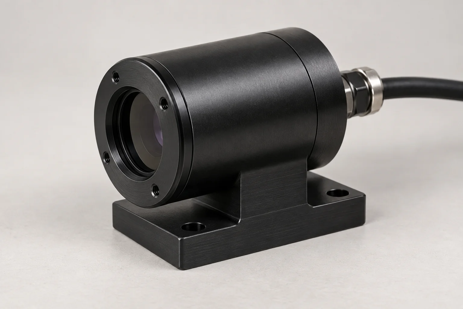
Bodies for optical, proximity, monitoring and environmental sensors. Coordinate the sensor aperture, cable entry, mounting holes and alignment surfaces.
Discuss this housing →
PRECISION STARTS AT THE INTERFACE.
TOPS Plastics manufactures custom plastic housings for sensors, instruments, electronics, connectors, automation systems and industrial equipment. We CNC machine internal cavities, mounting bosses, threaded inserts, connector interfaces, sealing surfaces, slots, ports and precision assembly features according to customer CAD models and drawings.
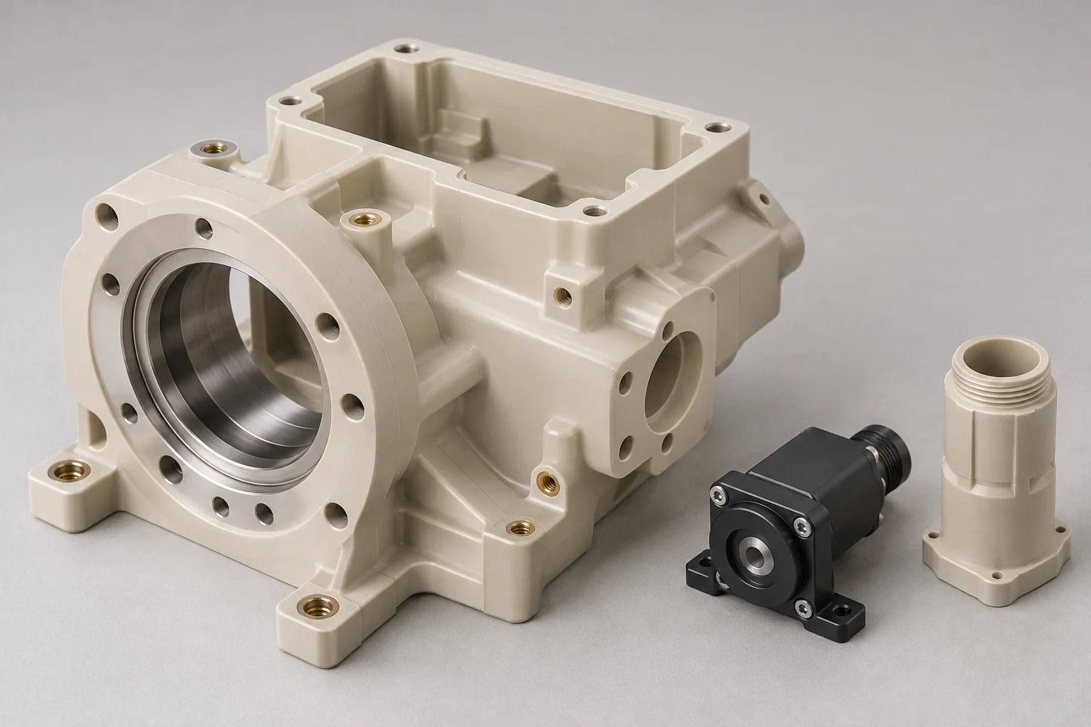
Start with the function and mating parts. We review the material, geometry, accessible features and critical interfaces before confirming the machining and inspection scope.
| Feature | Functional requirement |
|---|---|
| Housing types | Sensor, connector, instrument, electronics, motor, actuator, valve, pump, bearing and equipment housings |
| Materials | ABS, POM, PEEK, Polycarbonate, PEI, PPS and other specified engineering plastics |
| Features | Internal cavities, mounting bosses, bores, ports, slots, threads and sealing grooves |
| Hardware | Specified inserts, screws, pins, brackets and bushings, subject to installation review |
| Processes | CNC milling, turning, 5-axis machining where justified, drilling and tapping |
| Production | Prototype, low-volume and repeat production to controlled revisions |
| Input | 3D CAD, dimensioned 2D drawing or a reference sample for feasibility review |
| Inspection | Critical interfaces, bores, flatness, position and assembly fit to the agreed plan |
Find the structural body that matches your component and its working interfaces. Each housing is manufactured to the approved drawing, material and inspection requirements.
Bodies for optical, proximity, monitoring and environmental sensors. Coordinate the sensor aperture, cable entry, mounting holes and alignment surfaces.
Discuss this housing →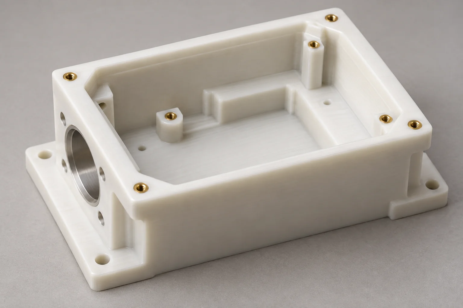
Structural bodies for laboratory, measurement and industrial instruments, with internal pockets, locating features and accessible mounting interfaces.
Discuss this housing →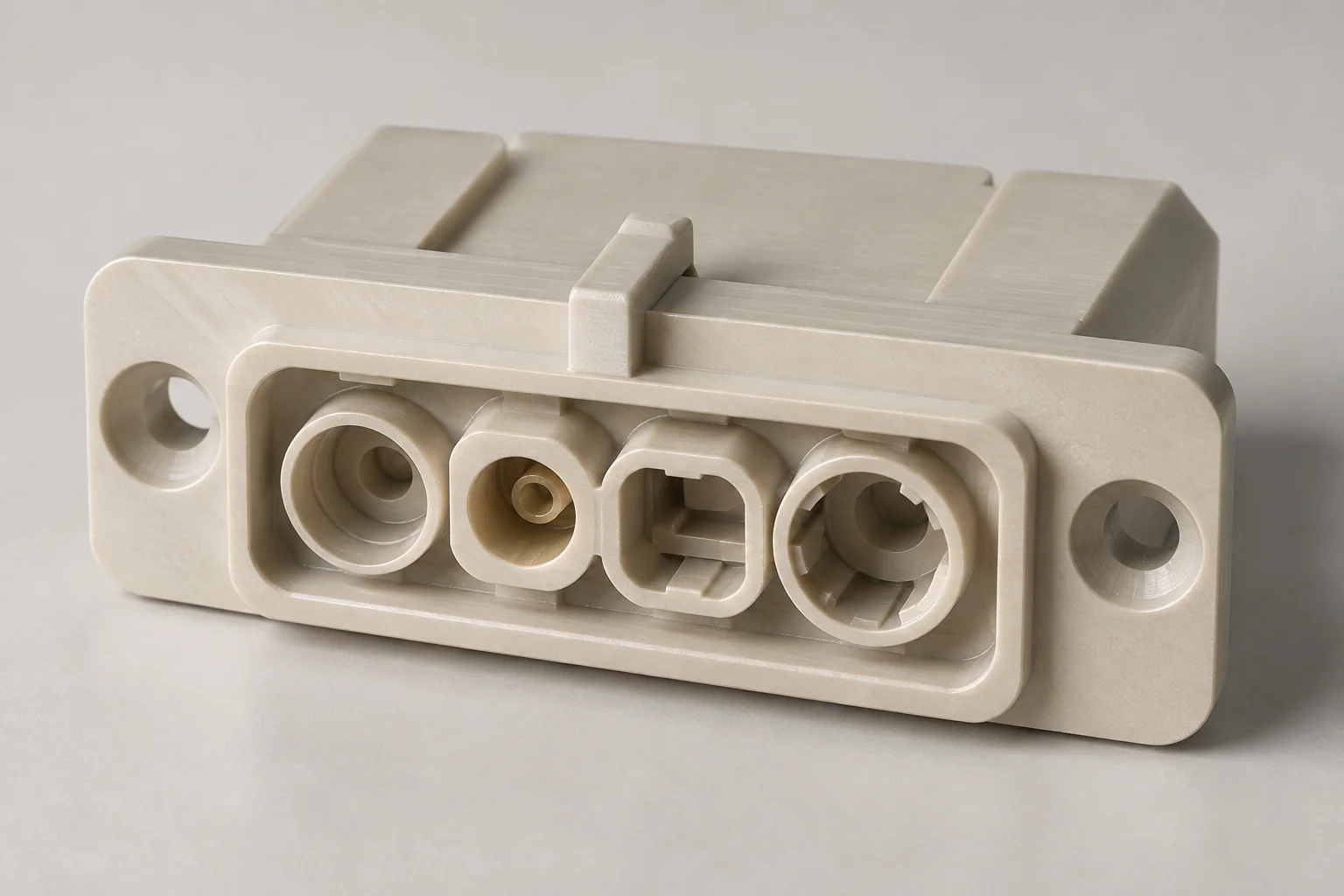
Machined cavities and keyed interfaces for electrical connectors, terminals and cables. Match the mating hardware, contact retention and operating temperature.
Discuss this housing →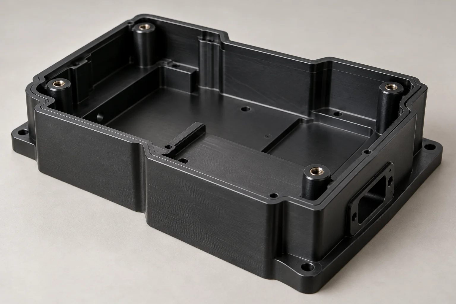
Support boards, electronics modules and control components with defined pockets, mounting features, connector positions and space for wiring and heat-generating parts.
Discuss this housing →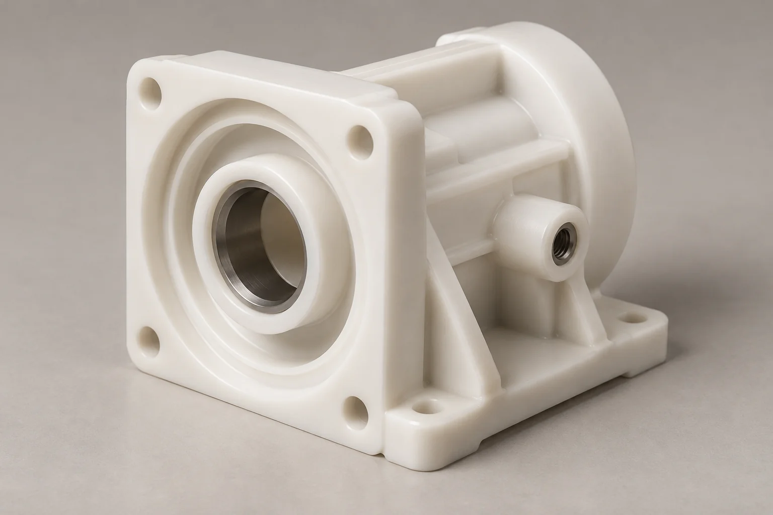
Bodies that support motors or actuators and coordinate shaft, bearing, sensor and machine-mounting interfaces. Define structural and thermal loads.
Discuss this housing →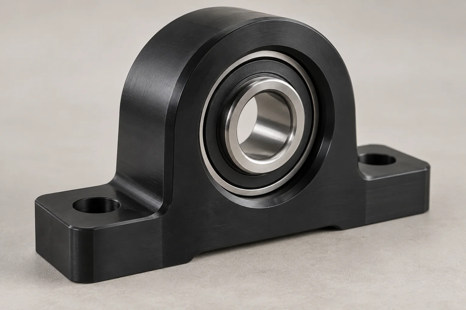
Hold bearings or bushings in a polymer structure. Bore size, roundness, wall thickness and the material response to fit and load need coordinated review.
Discuss this housing →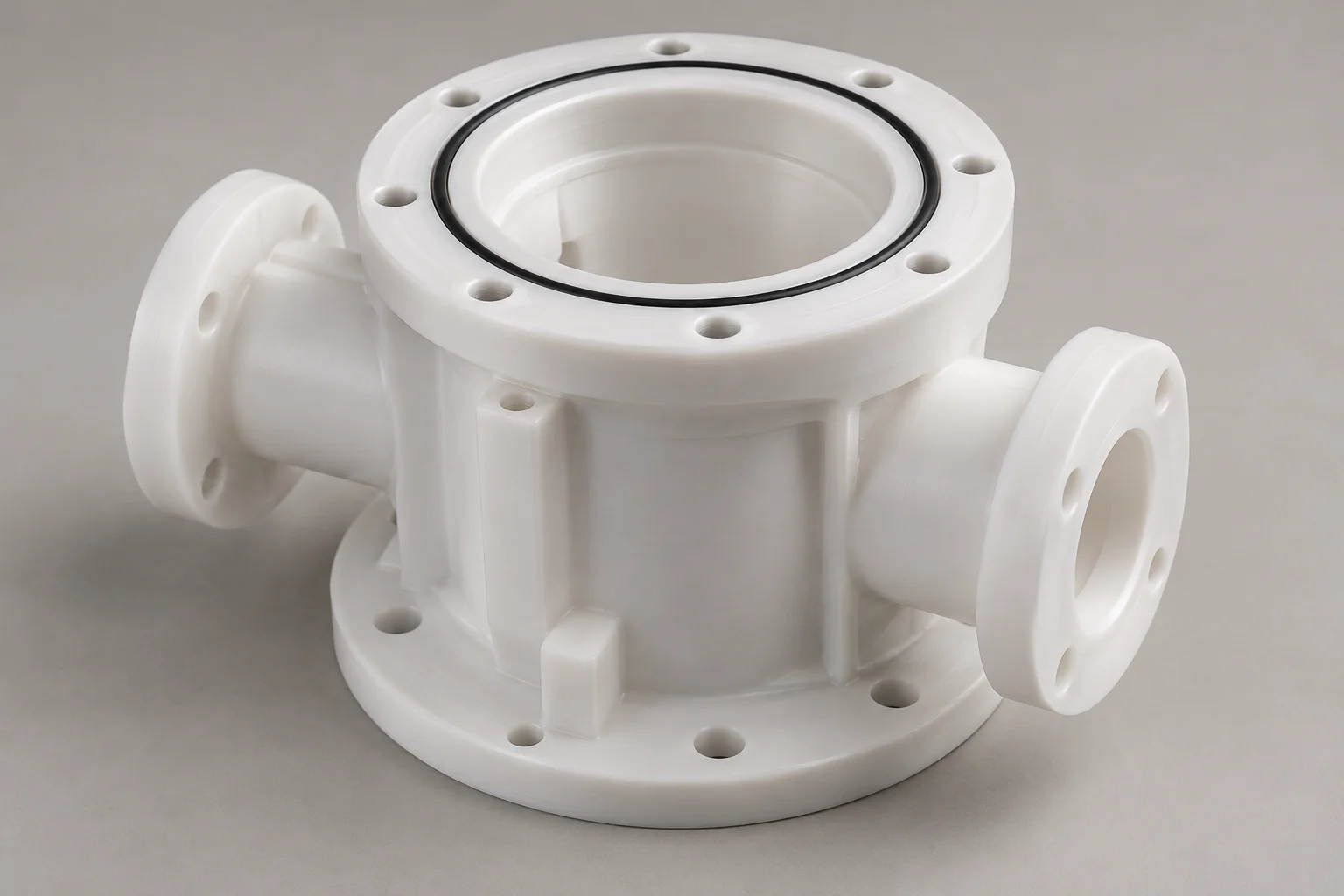
Specified chemical-resistant polymers for fluid-system bodies. Review the medium, pressure, temperature, seals and ports as one operating system.
Discuss this housing →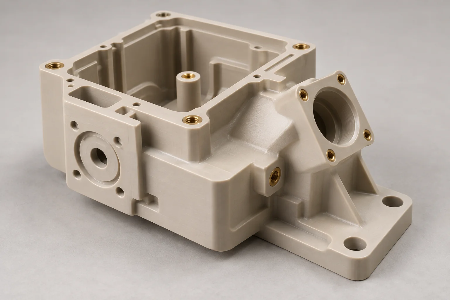
Irregular profiles, multi-face components, complex cavities, angled ports, integrated brackets and custom mounting interfaces, reviewed for tool access and fixturing.
Discuss this housing →A plastic housing is a structural or protective component designed around a specific mechanical, electrical or fluid-system function. It locates, supports, protects or interfaces with sensors, connectors, bearings, motors, electronics or valves.
A housing may integrate internal bores, alignment features, bearing seats, mounting faces and sealing surfaces into one body. It can remain open or form part of a larger assembly; a lid is not what defines its function.
The drawing should connect each critical feature to its mating component and functional datum. These relationships guide material selection, machining and inspection more usefully than the outer shape alone.
A housing is usually part of the machine or device structure, while an enclosure primarily surrounds and protects a complete assembly. The terms can overlap, so the drawing and function determine the actual requirements.
| Factor | Plastic housing | Plastic enclosure |
|---|---|---|
| Main function | Structural body, component location or functional support | Protective case around a system or group of components |
| Geometry | Often integrated, stepped or mechanically complex | Often case or box oriented, with lids or panels |
| Precision interfaces | Bores, mounting datums and mating features may be critical | Application dependent; component mounting and panel fit may be critical |
| Internal cavities | Functional geometry around a component or mechanism | Space and access for the overall system |
| Bearings / bores | Common in mechanical housing applications | Less typical, but possible in custom designs |
| Connector interfaces | Often integrated into a locating or structural body | Frequently arranged in removable panels or case walls |
| Buyer priorities | Fit, alignment, load path and component function | Protection, service access and environmental conditions |
CNC machining can support prototypes and suitable production runs in engineering plastic stock. The process choice still depends on size, access, material, quantity and total project cost.
Produce suitable housings without a dedicated injection mold. Programming, setup and custom fixtures may still be required.
Machine accessible pockets, stepped bores and integrated mounting features directly from the released model.
Focus dimensional control on the bearing, sensor, connector and mounting relationships that affect assembly.
Use specified PEEK, POM, PEI, PPS or other available stock grades, with supplier data appropriate to the application.
Revise CAD and programming without mold rework. A change may still affect fixtures, material stock and inspection.
Consider 5-axis machining for angled ports and accessible multi-face geometry when it reduces handling or improves the machining strategy.
POM is a useful starting point for precision mechanical housings, ABS for economical development parts, PC for impact-focused designs, PEEK for demanding thermal or chemical duty, and PEI or PPS for selected electrical and elevated-temperature applications. Confirm the exact grade and conditions.
| Material | Useful characteristics | Typical housing use |
|---|---|---|
| ABS | Practical cost and machinability; stress and stiffness need review | General equipment bodies and prototypes |
| POM / Delrin | Low moisture uptake and good dimensional stability under suitable conditions | Precision mechanical housings and mounting bodies |
| Polycarbonate | Impact toughness and available transparent grades | Protective housings and visible component interfaces |
| Acrylic / PMMA | Optical clarity and polished appearance; relatively brittle | Observation and display-related housings |
| PEEK | Mechanical, thermal and chemical performance in specified grades | Demanding technical and equipment housings |
| PEI / Ultem | Heat resistance and electrical insulation; flame data are grade specific | Electronics and higher-temperature instrument bodies |
| PPS | Chemical resistance and thermal stability in suitable grades | Sensor, electrical and process housings |
| PVDF | Chemical resistance; high-purity grades available where specified | Semiconductor equipment and fluid-system bodies |
| PTFE | Broad chemical resistance; low stiffness and creep require allowance | Specialized chemical housings with suitable support |
Material family names do not establish a product certification or a universal operating limit. Compare the stock grade, temperature, load, chemicals, humidity and required documents. Machining stock and molding resin grades are not automatically equivalent.
Build the cavity around the component envelope and its locating interfaces. Preserve enough material to support bores, fastening loads and the housing after it is released from the fixture.
LOCATE THE FUNCTIONAL FEATURES
Relate the central bore and sensor opening to the mounting face. Preserve the section between the cavity, bearing seat and fastening points.
Provide component clearance and realistic cutter access without unnecessarily weakening the walls. Include tool radii and the deepest required features.
Define bore size, roundness, fit and supporting wall thickness together. Assess interference, load, temperature and polymer creep before releasing the fit.
Reference sensor faces, apertures and mounting holes to functional datums for repeatable positioning. Identify any alignment adjustment.
Coordinate the cavity, keying, fastening pattern and insertion travel with the actual mating hardware. Allow for thermal movement where relevant.
Reserve board and cable space, connector access and clearance around heat-generating components. Include assembly tools and service access.
Review a section view or mating-component model with the housing drawing. The conceptual interface diagram below shows feature relationships only; it does not prescribe dimensions, tolerances, bearing interference or electrical clearances.
Fasteners transfer load through the surrounding polymer. Insert design must consider wall thickness, installation method, fastener preload and creep; a metal insert cannot compensate for an inadequately supported plastic boss.
Locate and fasten internal components using drawing-defined boss positions, heights and supporting sections. Review tool access around the boss.
Consider direct threads for suitable loads, engagement and service frequency. Define thread form and avoid relying on repeated high preload in a soft polymer.
Use specified inserts when repeated opening or joint requirements justify them. Match the insert and installation method to the polymer, boss and application.
Provide controlled alignment and retention. Review interference, edge distance, temperature and local stress rather than copying a metal fit.
Add specified reinforcement where the load path requires it. Coordinate contact areas, differential expansion, hardware access and assembly sequence.
Dimension each interface from its mating part and functional datum. Confirm installation travel and access in the assembled product, not only the nominal opening outline.
Custom outlines, keys and fixing patterns that align with mating connector hardware.
Openings and routing envelopes with clearance for the cable and defined strain relief.
Specified threads, panel thickness and sealing contact for the selected gland.
Sensing openings and locating faces aligned with the sensor operating direction.
Drawing-defined window seats and retention features; specify material, clear area and optical acceptance.
Bores, steps and clearances related to shaft alignment, support and any seal.
Drawing-defined port geometry, threads and seals reviewed with pressure, medium and temperature.
Mounting openings, anti-rotation features and operating clearance for controls.
Indicator apertures or light-pipe seats with defined location and retention.
Panel or display pockets with practical corner radii, depth and access to fixings.
Seal the complete interface, including the body, mating component and all penetrations. Define the seal supplier requirements and the validation plan before assigning an environmental rating.
Local sealing around ports, bores or mating faces. Specify seal size, groove geometry, compression and finish for the actual material and duty.
Cover or component joints need controlled contact width, flatness and fastening support to achieve the specified gasket compression.
Shaft or cylindrical interfaces may use suitable radial seals. Review motion, shaft finish, alignment, temperature and wear with the seal supplier.
Permanent joints require compatible materials, an agreed bonding process, adequate joint geometry and a defined inspection approach.
A machined groove or gasket does not guarantee an IP rating. Dust or moisture protection requires validation of the complete configuration and testing where specified. Pressure, leakage, chemical compatibility and shaft sealing are separate requirements that also need a defined acceptance plan.
Critical bores, mating faces, sensor locations and mounting interfaces usually matter more than a tight tolerance on every exterior surface. Use datums that represent the assembled function.
| Feature | Functional requirement |
|---|---|
| Bearing bore | Bearing retention, running behavior and shaft alignment; control fit, roundness and support |
| Sensor location | Measurement alignment and repeatable sensing position |
| Connector interface | Mating fit, keying and insertion alignment |
| Mating face flatness | Sealing contact, closure and component seating |
| Boss location | Position and support of the attached component |
| Port position | Alignment to pipes, fittings and other system interfaces |
| Cavity depth | Internal component clearance and remaining wall thickness |
| Wall thickness | Local stiffness and dimensional stability |
| Datum relationships | Consistent alignment across multiple components and machined faces |
Identify GD&T, critical dimensions and the measurement state on the drawing. Agree inspection temperature, stabilization, free-state or restrained condition and the use of gauges or customer mating parts. The required tolerance must be assessed against material, geometry and the machining route.
A housing must hold its interfaces after unclamping, assembly and environmental exposure. Polymer grade, stock stress, geometry and service conditions all affect the final dimensions.
Walls can flex under cutting, clamping or fastener loads. Keep adequate support around bores, inserts and mounting faces.
Removing stock unevenly can release residual stress and distort the body. Review machining sequence, roughing and any agreed stabilization steps.
Large pockets reduce structural stiffness. Evaluate the remaining section and the load path between mounting points and component seats.
Thermal expansion and moisture uptake can change fits. Define service and inspection conditions, especially for close mating relationships.
Nylon moisture uptake can change dimensions. ABS can distort when stock stress is released or sections become flexible; Polycarbonate requires attention to machining stress and chemical stress cracking. POM and PEEK often offer useful precision stability, but neither is immune to thermal movement, residual stress or creep.
There is no universal minimum wall or interference value for every plastic housing. Select the section and fit from the exact grade, housing size, load duration, temperature and mating-component requirements.
Define the functional interfaces first, then design the surrounding body for machining, support and assembly.
Start from bearing seats, sensor locations, connector geometry and mounting faces; keep their relationships clear.
Long tool reach can reduce rigidity, access and machining efficiency. Consider access openings or a coordinated multi-part construction.
Allow the cutter radius in internal corners. Mark the locations where a mating part requires an alternative solution.
Support bores, threads and inserts with sufficient surrounding material for machining and service loads.
Reference multi-face features to the same functional locating scheme used for assembly and inspection.
Interference can deform the housing or relax through creep. Assess retention over the service temperature and load duration.
Allow room for components, fasteners, tools and the intended installation sequence.
Specify the relevant finish, flatness, groove dimensions and protection from handling damage.
Choose the machining sequence around critical interfaces, access, stock support and the material response. Confirm hardware installation and inspection as part of the project scope.
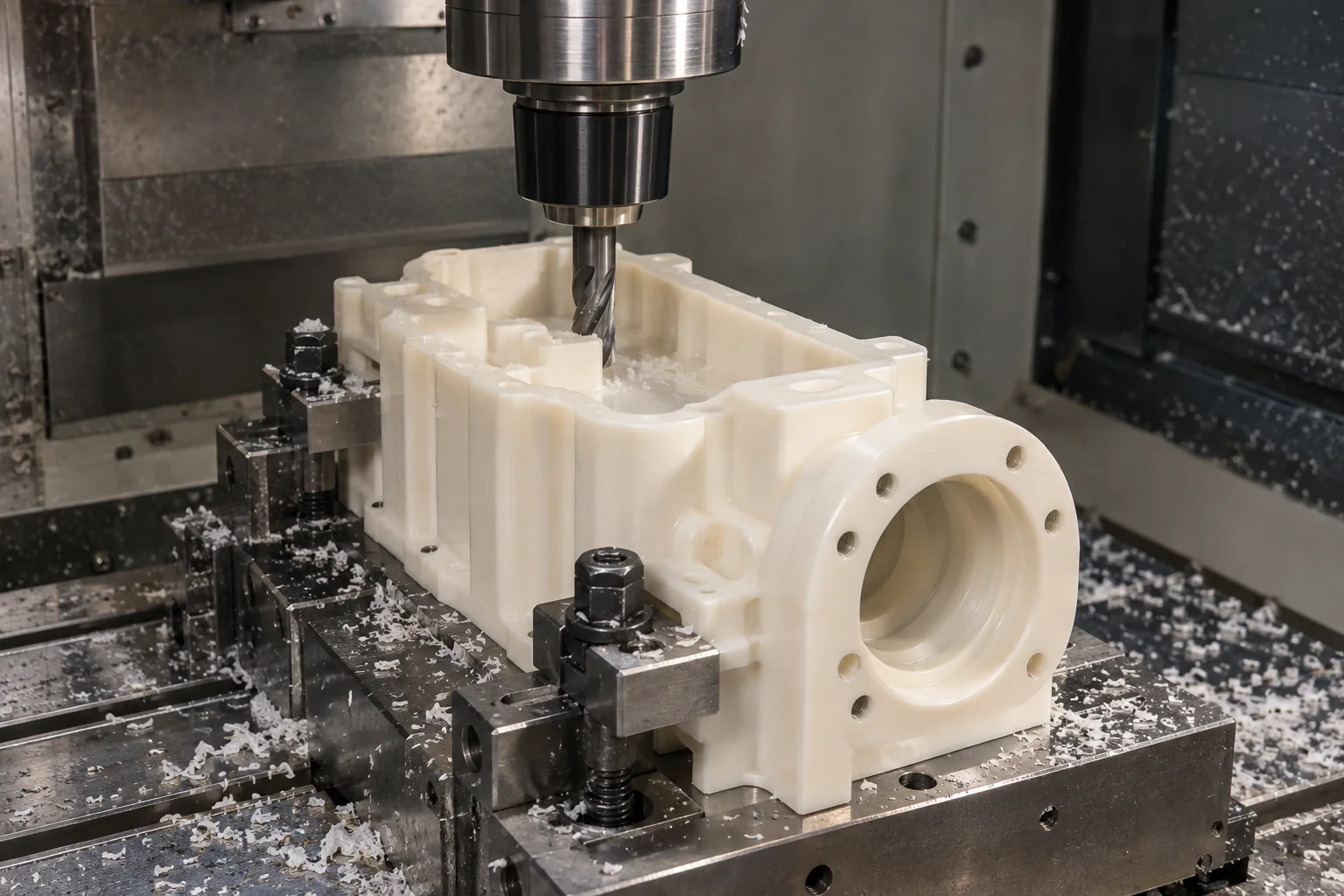
Machine internal cavities, mounting faces, slots, bosses, ports and accessible outer geometry with a reviewed clamping strategy.
Consider angled ports, multiple faces and complex accessible geometry where the process can reduce repositioning or improve access.
Produce rotational or cylindrical housings, stepped bores, shoulders and sealing diameters from suitable stock.
Machine interface holes and threads with specified position, engagement and material support.
Install agreed inserts, pins, bushings or hardware using the specified method and assembly requirements.
Verify critical fits and datums against the drawing and agreed measurement conditions before packaging.
Consider plastics for weight, insulation, chemical compatibility or RF access. Consider metals when high stiffness, heat dissipation or structural loads dominate. Compare the actual grade, alloy and geometry.
| Factor | Plastic housing | Metal housing |
|---|---|---|
| Weight | Often lower density; section thickness affects final weight | Often heavier for comparable geometry |
| Corrosion resistance | Depends on polymer, chemical, concentration, stress and temperature | Depends on alloy, coating and exposure |
| Electrical insulation | Many grades are insulating; conductive fillers and conditions can change behavior | Generally conductive and may require electrical isolation |
| High-temperature capability | Grade-specific limits and thermal movement need review | Often more suitable for very high temperature and heat dissipation |
| Structural stiffness | Typically lower modulus; design section and creep matter | Typically greater stiffness, subject to alloy and geometry |
| Chemical options | Wide polymer choices, each with compatibility limits | Alloy-dependent compatibility and corrosion behavior |
| RF transparency | Possible with selected grades, thicknesses and frequencies; validate the product | Conductive walls often need a designed antenna opening or window |
| Complex machining | Accessible complex geometry can be machined | Accessible complex geometry can also be machined |
A material change can affect bearing fits, thermal paths, mounting loads, electrical insulation and shielding. Review the complete assembly rather than replacing metal with plastic at identical dimensions by default.
Application examples show possible component functions. Material suitability, cleanliness, documentation and product qualification must be defined for each project.
Specified PEEK, PVDF, PPS or PEI housings for technical equipment, with agreed cleanliness, traceability and packaging.
Connector, sensor and PCB-support housings with electrical, thermal and assembly requirements.
Motor, actuator, sensor and controller bodies with defined loads, mounting and alignment.
Instrument and device housings in specified grades with project-defined cleaning and documentation requirements.
Valve, pump and sensor bodies reviewed for medium, pressure, temperature and sealing.
Instrument bodies and measurement-device housings with critical sensor and component locations.
Bearing, sensor and actuator supports designed around the machine load path and maintenance access.
The inspection plan follows the released material, datums and critical interfaces. Agree sampling, reports, gauges and supplied mating components before production.
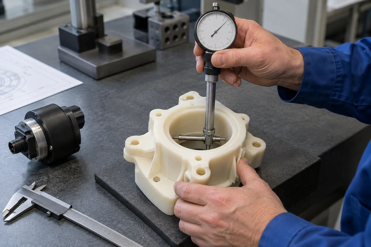
Check the specified stock grade and required supplier documentation.
Confirm revision, functional references and critical dimensions.
Measure size and specified geometric requirements using suitable equipment and conditions.
Check pocket depth, clearances and drawing-defined remaining sections.
Verify mounting, sensor, connector and port locations relative to datums.
Inspect the agreed contact surfaces in the specified free or restrained state.
Check part identity, installation location and specified assembly requirements.
Use agreed customer-supplied components or gauges to verify interfaces where included in scope.
Check edges, internal openings and visible surfaces to agreed acceptance criteria.
Protect bores, mating faces, sealing grooves and installed hardware from shipment damage.
Fit checks with bearings, sensors or customer components can reveal interface issues that isolated dimensions miss. They supplement the agreed dimensional plan; they do not establish a load, pressure, environmental or product certification.
Maintain the same functional references as the design moves from initial evaluation to repeat supply.
Validate geometry, component fit, connector position and assembly sequence. Incorporate approved changes into the released drawing.
Machine suitable specialized industrial housings without dedicated mold tooling, subject to access, stock size and total-cost review.
Control material grade, CAD and program revision, hardware BOM and critical-interface inspection. Review changes before the next order.
Internal interfaces, bores, mounting datums, inserts, sealing surfaces, wall stiffness and material stability determine how a housing supports the complete assembly.
Review your released CAD, drawings and mating interfaces before production.
Match the exact stock grade to the function and operating conditions.
Coordinate pockets, remaining sections and tool access around the installed component.
Review complex surfaces and angled interfaces for an appropriate machining route.
Focus tolerances and inspection on the features that determine assembly fit.
Define installation requirements and responsibility for specified hardware.
Maintain approved material, design and inspection revisions.
Combine drawing measurements with agreed gauges or mating components.
Practical answers about housing materials, bearing seats, inserts, sealing and drawing-defined interfaces.
A plastic housing is a structural or protective body that locates, supports or interfaces with a specific sensor, connector, bearing, motor, electronic module or fluid-system component.
A housing usually forms part of the device structure and contains functional locating or mating interfaces. An enclosure primarily surrounds and protects a system, often with a lid or panels. Actual designs can combine both functions.
POM is often a useful starting point for mechanical precision, while PEEK, PEI or PPS may suit demanding thermal, chemical or electrical requirements. Select the exact grade after reviewing load, environment, size and tolerances.
Yes. Specified inserts can be reviewed for suitable installation in the chosen plastic. Boss wall thickness, insertion method, fastener preload, creep and service frequency all affect the joint.
Yes. Accessible bearing seats can be machined to drawing-defined fits. Review bore size, roundness, supporting wall, interference, temperature and load duration together before confirming the fit.
Yes. Accessible O-ring grooves, gasket faces and radial sealing interfaces can be reviewed for machining. The complete design and validation plan determine sealing performance; the groove alone does not establish a rating.
Critical bores, sensor locations, connector interfaces, mating faces and mounting datums usually matter most. Specify their relationships and measurement conditions rather than applying a tight tolerance to all surfaces.
Consider PEEK when the required temperature, chemical exposure or mechanical duty exceeds the capability of suitable POM or ABS grades. Compare exact-grade data, operating conditions, machining requirements and cost.
Yes. CNC machining can suit low-volume industrial housings without a dedicated injection mold. Setup, fixtures, accessible geometry and the lifetime order quantity still influence the economics.
We can review a CAD model, dimensioned drawing or physical sample for feasibility. A sample may require dimensional reconstruction and an approved drawing. Include mating-component details, material, quantity and critical interfaces.
YOUR MATING PARTS. YOUR DATUMS. YOUR HOUSING.
Upload your housing CAD model or engineering drawing and specify the material, quantity, critical bores, internal cavities, mounting interfaces, inserts, sealing requirements and application. Our team can review the housing design and machining approach before quotation.
Company, name, email and phone are required. Country, part number, quantity and drawing upload are optional. Include technical details in your drawing package or share them by email.
info@tops-precision.comSTEP / STP / IGES / X_T / DWG / DXF / PDF or ZIP, maximum 10 MB. Larger packages can be shared by email. Agree confidential-file handling before sending sensitive drawings.