01
Fluid Distribution Manifolds
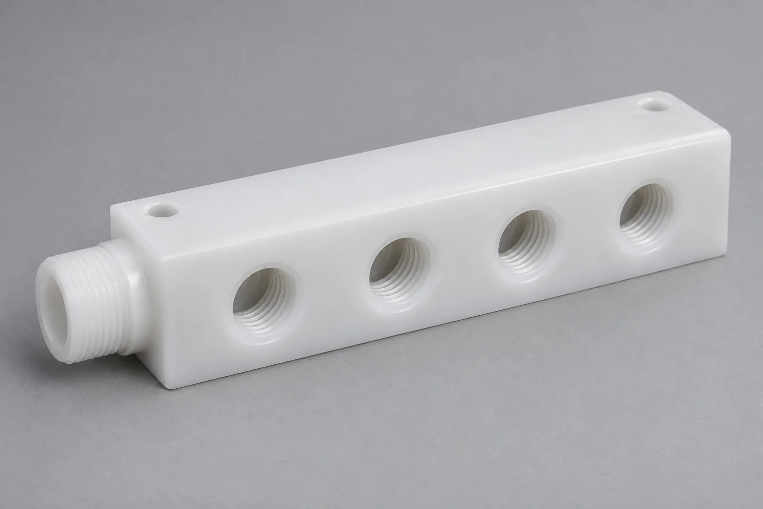
Route one inlet to multiple outlets or combine separate flow paths. Specify the intended connections and any circuits that must remain isolated.
Discuss this manifold →
ROUTE THE MEDIUM. DEFINE EVERY INTERFACE.
TOPS Plastics manufactures custom CNC machined plastic manifolds for fluid distribution, chemical handling, pneumatic, vacuum, laboratory, semiconductor and industrial equipment. We machine custom ports, internal passages, threaded connections, O-ring grooves, sealing faces and mounting features in PVDF, PEEK, PTFE, PVC, PP, Acrylic and other specified engineering plastics to customer drawings.
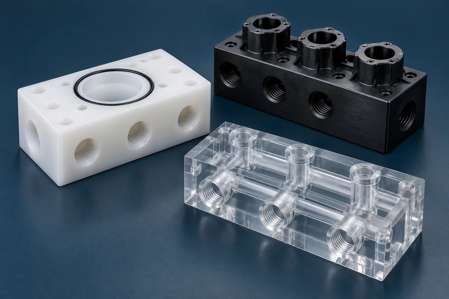
Start with the fluid circuit and mating interfaces. We review the drawing, material and accessible machining features before confirming a manufacturing and inspection plan.
| Capability | Drawing-based scope |
|---|---|
| Manifold types | Fluid, gas, pneumatic, vacuum, chemical, valve and laboratory manifolds |
| Materials | PVDF, PEEK, PTFE, PVC, PP, Acrylic, Polycarbonate and POM; CPVC and other specified grades subject to sourcing and feasibility review |
| Port types | NPT, BSP / BSPT, metric, straight-thread O-ring, barb, flange and custom interfaces to the specified standard |
| Features | Cross holes, internal passages, O-ring grooves, sensor ports, drain openings and mounting holes |
| Processes | CNC milling, drilling, tapping, boring and 5-axis machining where access and geometry justify it |
| Production | Prototype, low-volume and recurring production to controlled revisions |
| Input | 3D CAD, dimensioned 2D drawings or a sample for feasibility and dimensional review |
| Inspection | Port relationships, threads, sealing faces, flatness and drawing dimensions; special tests agreed separately |
Explore the manifold geometry that matches your machine. Each component is reviewed against its port map, sealing interfaces and operating duty.
Route one inlet to multiple outlets or combine separate flow paths. Specify the intended connections and any circuits that must remain isolated.
Discuss this manifold →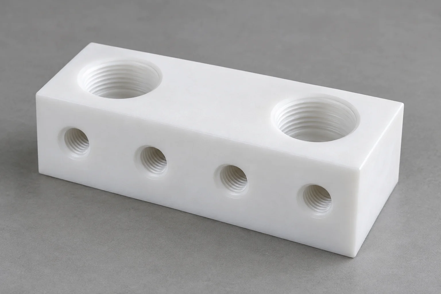
Select the exact polymer and seals for the process chemical, concentration, temperature and exposure duration; corrosion resistance alone does not establish suitability.
Discuss this manifold →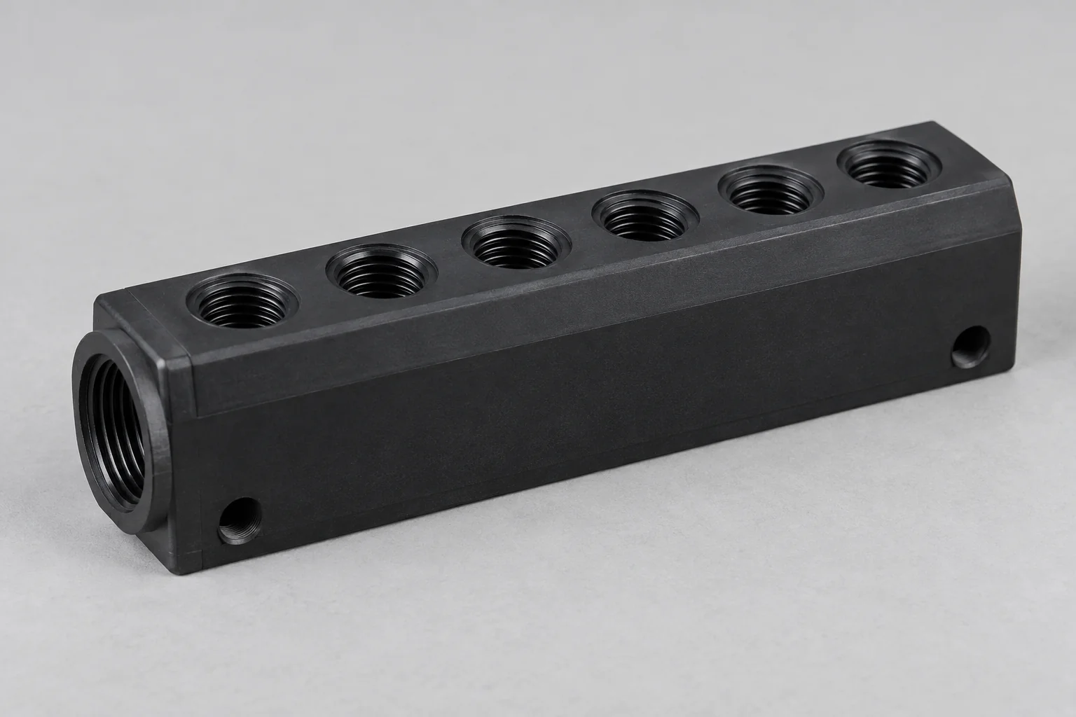
Distribute compressed air to equipment circuits. Define pressure, fitting interfaces, mounting pattern and any lubrication or condensate exposure.
Discuss this manifold →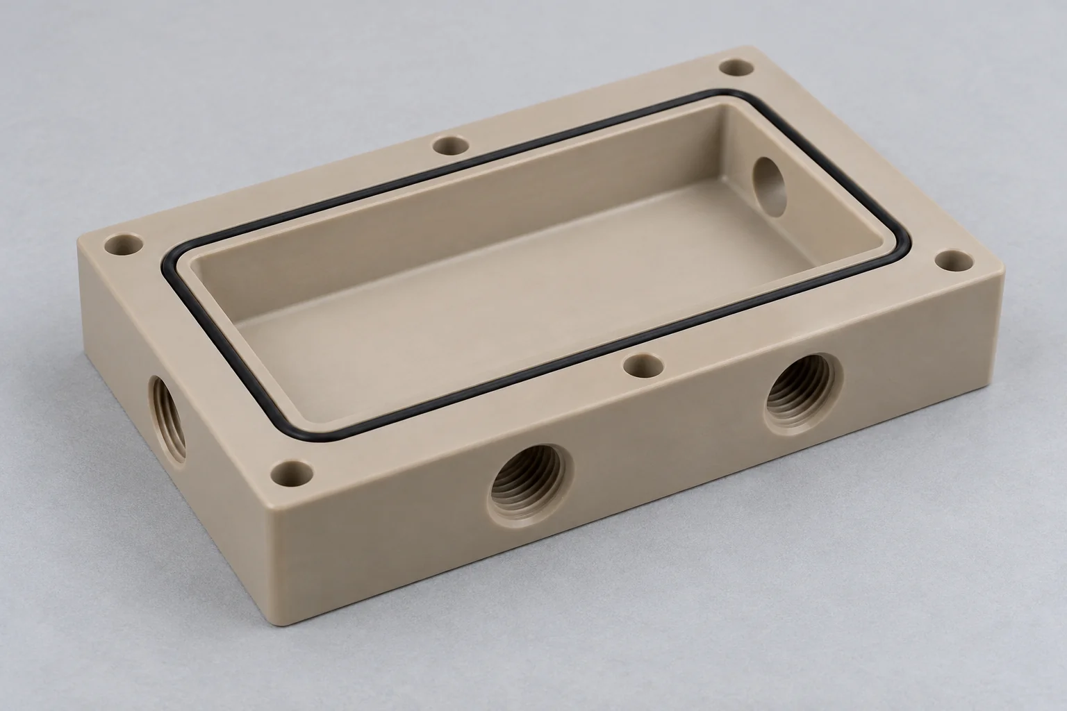
Route vacuum for laboratory, analytical and equipment systems. Identify the vacuum level, allowable leakage, permeation and outgassing requirements.
Discuss this manifold →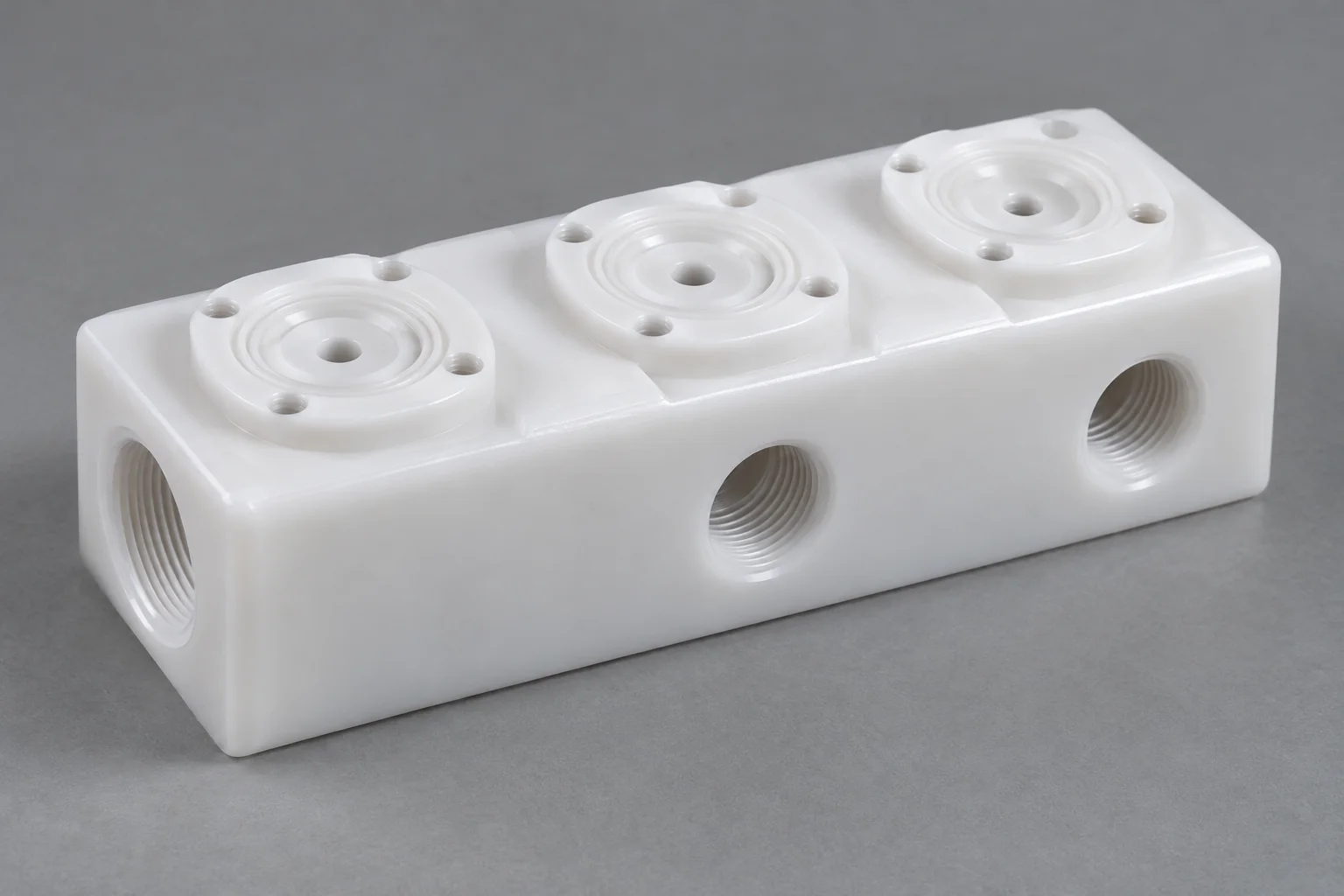
Bring valve seats, port interfaces and routing features into one machined body. Provide the mating valve drawing and required sealing geometry.
Discuss this manifold →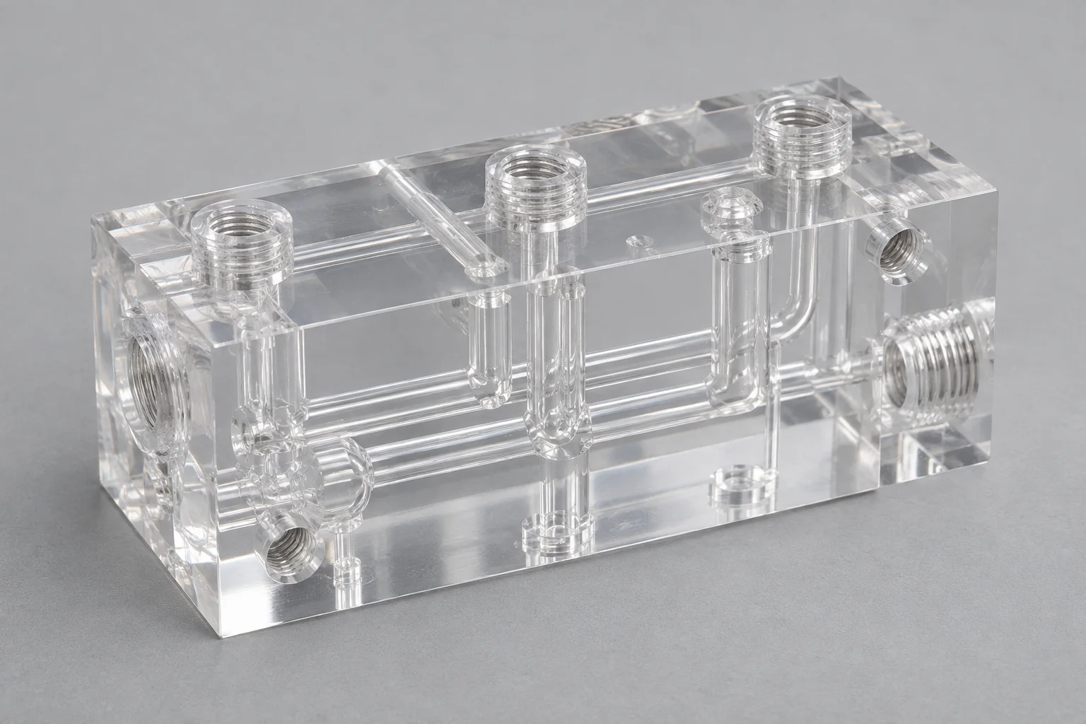
Fluid-routing blocks for sample handling, instruments and diagnostic equipment, with project-defined dead volume, media compatibility and cleaning requirements.
Discuss this manifold →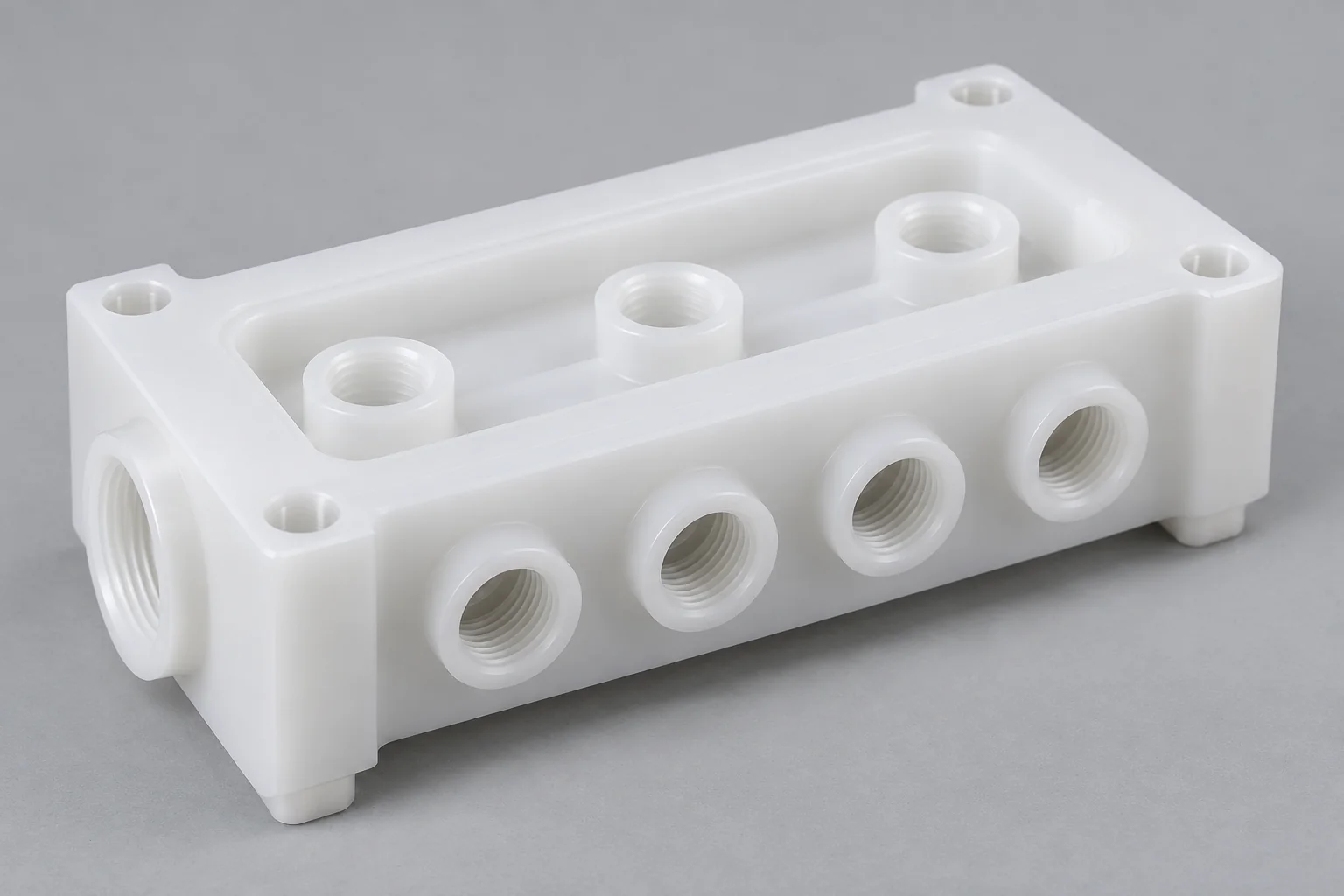
Specified-grade polymer manifolds for wet-process and chemical-delivery equipment. Purity, traceability, particles and packaging must be defined and agreed for the project.
Discuss this manifold →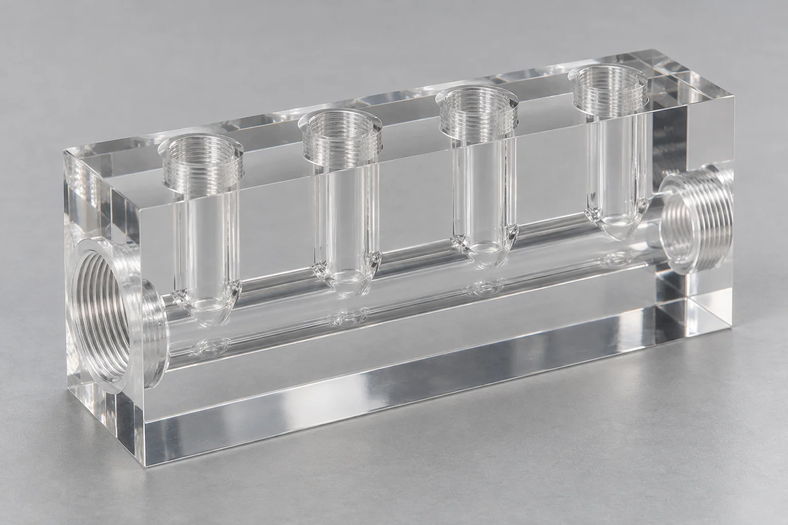
Acrylic or Polycarbonate blocks for observing channels, bubbles or visible contamination where chemical, pressure and temperature conditions permit.
Discuss this manifold →Plastic manifolds are blocks or plates with ports, internal channels and connection features that route, distribute, combine or isolate liquids, gases, vacuum or process media within equipment.
CNC machining suits nonstandard port positions, intersecting drilled passages, sealing faces and mounting features. A fluid circuit drawing should identify which ports connect and which must stay separate; an external CAD model alone may not communicate that intent.
A manifold is a fluid-routing component. A plastic housing primarily protects or supports equipment, while a plastic insulator provides an electrical barrier. The manufacturing process may be shared, but the functional acceptance requirements differ.
Select a polymer because it fits the actual fluid and operating duty. Consolidating suitable connections into one body can simplify equipment routing, but every remaining interface still needs a defined seal.
PVDF, PTFE, PVC and PP offer useful resistance to selected chemicals. Check exact-grade compatibility with the complete process and cleaning cycle.
Appropriate polymers avoid metallic rust, while chemical attack, swelling and stress cracking still require evaluation.
Engineering polymers generally have lower density than metal blocks, helping reduce equipment mass.
Unfilled insulating grades can separate conductive equipment features where the system design calls for it.
Acrylic and Polycarbonate can make channels and bubbles visible in suitable service. Clarity does not prove cleanliness or correct flow.
Machine the port arrangement around the equipment and fittings instead of adapting every interface to a standard distribution block.
PVDF is a common candidate for specified high-purity chemical systems; PTFE offers broad chemical resistance, PVC / CPVC and PP can suit economical process equipment, and Acrylic or Polycarbonate provide transparent options. The exact medium and service conditions decide.
| Material | Main strength | Typical direction / design consideration |
|---|---|---|
| PVDF | Chemical resistance with useful stiffness; purity-focused grades available | Semiconductor and process-fluid systems. Verify grade, extractables and chemical concentration / temperature. |
| PEEK | Strength, elevated-temperature capability and broad chemical resistance | Technical manifolds under demanding thermal or mechanical duty; check chemical exceptions and filler suitability. |
| PTFE | Very broad chemical resistance | Aggressive-media systems; low stiffness, creep and fitting loads require particular support and sealing attention. |
| PVC / CPVC | Economical options for selected water and chemical systems | Confirm temperature, impact conditions and exact formulation. CPVC availability and machining scope are reviewed separately. |
| Polypropylene | Chemical resistance and potential for welded assemblies | Process equipment; account for thermal expansion, stiffness and the suitability of the joining method. |
| Acrylic / PMMA | Transparency and good visual access | Observation and laboratory manifolds; review solvents, residual stress and crazing risks. |
| Polycarbonate | Transparency with higher impact resistance than Acrylic | Visual or protective fluid blocks; assess chemical stress cracking and seal / cleaner compatibility. |
| POM / Delrin | Machinability and dimensional consistency | General mechanical or selected fluid blocks; not a universal choice for aggressive chemicals or high-purity duty. |
Evaluate the manifold body, fittings, plugs, O-rings, gaskets and any adhesive as one wetted system. A compatible body material does not compensate for an incompatible seal.
High-purity, food-contact or medical documentation belongs to the exact purchased grade and project requirements. A polymer family name does not establish equipment approval, cleanliness or certification.
Define the circuit before finalizing the block. A port map, channel geometry and closure drawing should make each connection and isolation boundary unambiguous.
ONE CIRCUIT. DEFINED CONNECTIONS.
A simple distribution circuit connects one inlet to four branches. The drilling-access opening at the far end needs a defined closure.
Conceptual circuit only. It does not specify dimensions, flow balance, plug retention or a pressure rating.
Allow space for thread diameter, remaining wall thickness, sealing lands, fittings, wrench access and assembly sequence. Dimension related ports from agreed datums.
Place intersecting passages so they connect as intended without breaking into an adjacent circuit. Review drill reach, alignment and intersection access.
Minimize trapped volumes where response time, sample carryover, draining or purity requires it. Identify acceptable residual volume and cleaning access.
Passage diameter, length, bends and intersections affect pressure drop and flow distribution. The system designer should specify flow and allowable pressure loss.
Drilling access can leave external openings. Define plug material, thread or retention, seal method and inspection before manufacture.
Specify the full connection standard, size, pitch, engagement and seal location. Similar-looking threads are not automatically interchangeable.
Tapered pipe threads may be specified for compatible fittings. Installation torque and wedging stress must suit the plastic wall and operating duty.
Distinguish parallel BSPP from tapered BSPT and state the required sealing arrangement. Do not substitute NPT for BSP thread forms.
Define pitch, depth, fit and whether the thread locates, retains or seals the connection; a metric thread alone does not define a fluid seal.
Separate retention from the seal where the design permits. Control the gland, shoulder, seat and fitting insertion depth.
Define tube dimensions, retention and clamp arrangement. Barbs may be machined features or separately specified fittings.
Bolted faces need a defined gasket, bolt pattern, flatness and load distribution that accounts for polymer creep.
Thread choice must consider remaining wall, fitting material, installation torque, pressure and creep. Metal-fitting torque assumptions should not be carried across to a plastic manifold. Use the fitting supplier’s approved method and validate the actual assembly.
Select the sealing method early, then machine the supporting geometry to the approved design. Seal material, compression and surface condition must match the fluid, temperature and pressure.
Control groove width, depth, corner geometry, gland fill, squeeze and surface condition for the selected seal. Specify whether the seal is axial or radial and static or moving.
Define face flatness, finish, gasket material, bolt layout and compression. Assembly loads must be distributed without distorting the body.
The thread form, fitting and approved sealant determine the sealing method. Sealants and assembly aids must also be compatible with the polymer and medium.
Multi-layer manifolds may use approved bonding or welding for suitable polymers. Review joint access, residual stress, bond-line exposure and test requirements separately.
A material name and port size do not establish a pressure rating. Provide the combined service envelope so body geometry, closures, seals and fittings can be reviewed together.
Identify water, air, gas, solvent, acid, base or process mixture, including concentration, contaminants and exposure duration.
State normal and peak pressure, surges, pulsation, duty cycle and any required proof-test condition. Include fitting and closure loads.
Define target vacuum, allowable leak rate, evacuation needs and relevant permeation / outgassing limits.
Give operating, peak, startup and cleaning temperatures. Polymer stiffness, expansion and chemical resistance vary with temperature.
Specify required flow by circuit, allowable pressure drop and whether balanced distribution or complete draining is required.
Include CIP, solvents, sterilization chemicals and cleaning frequency. Assess every wetted material against the complete cycle.
No universal maximum pressure applies to all plastic manifolds. The equipment designer must establish the permitted duty using exact-grade data, wall and port geometry, service life and assembly-specific validation.
Internal burrs, loose chips and rough channel intersections can obstruct flow, trap contamination or affect seals. Drilling strategy, accessible deburring, compatible cleaning and inspection should be planned for fluid-contact features.
Review drill breakout and intersecting passages. Specify accessible verification and acceptance criteria for features that cannot be viewed directly.
Remove loose edges at port entrances without changing the thread or sealing geometry. Protect the finished port from subsequent chips.
Define an appropriate cleaning / flushing method, drying and handling plan. Agree particle or residue limits and verification if the application needs them.
Call out finish and local defects that affect flow, sealing or retention. Cosmetic external finish is not an internal cleanliness specification.
Semiconductor and analytical projects may require specific particle, extractable or residue limits. Cleanroom processing, validated cleaning and special packaging are not assumed; request a project feasibility review and agree the verification provider and method.
Port relationships, sealing faces, O-ring grooves and cross-channel alignment usually deserve more attention than making every external dimension equally tight.
| Feature | Why it matters |
|---|---|
| Port position | Fitting alignment and interface to mating equipment |
| Port angle | Connection orientation, assembly access and intended routing |
| Thread depth | Engagement without bottoming, wall breakthrough or obstructing a passage |
| O-ring groove | Specified compression, support and seal placement |
| Sealing-face flatness | Uniform contact under the agreed assembly load |
| Cross-hole alignment | Flow continuity and isolation from adjacent circuits |
| Mounting-hole position | Equipment integration without forced assembly |
| Overall block flatness | Stable seating and body distortion control |
| Wall thickness | Structural integrity around channels, ports and closures |
Identify critical dimensions, GD&T and datums on the drawing. Tolerance feasibility depends on grade, geometry, stress release, temperature and measurement condition; no blanket machining tolerance is promised.
Provide a sectioned CAD model and a dimensioned drawing that communicate both the fluid circuit and how the block will be assembled.
Chemical compatibility, stiffness and temperature can change the wall, support and seal design.
Allow for machining, installation stresses, fitting loads and service creep; avoid thin webs between ports.
Where machining access permits, improve transitions and reduce trapped debris. Specify intentional intersections clearly.
Show O-ring glands, gaskets, approved thread sealing or bonded interfaces and the mating parts.
Review deep ports, angled bores, cross drilling, deburring and plug installation before freezing the design.
Identify drainage direction, sample carryover constraints and which branches must flush completely.
State particle / residue acceptance, cleaning compatibility, handling and packaging requirements.
Include normal, transient and cleaning conditions, intended life and any assembly-validation requirements.
Machining sequence follows the port map, datum structure and accessible fluid-contact features. Inspection and cleaning requirements are agreed with the drawing revision.
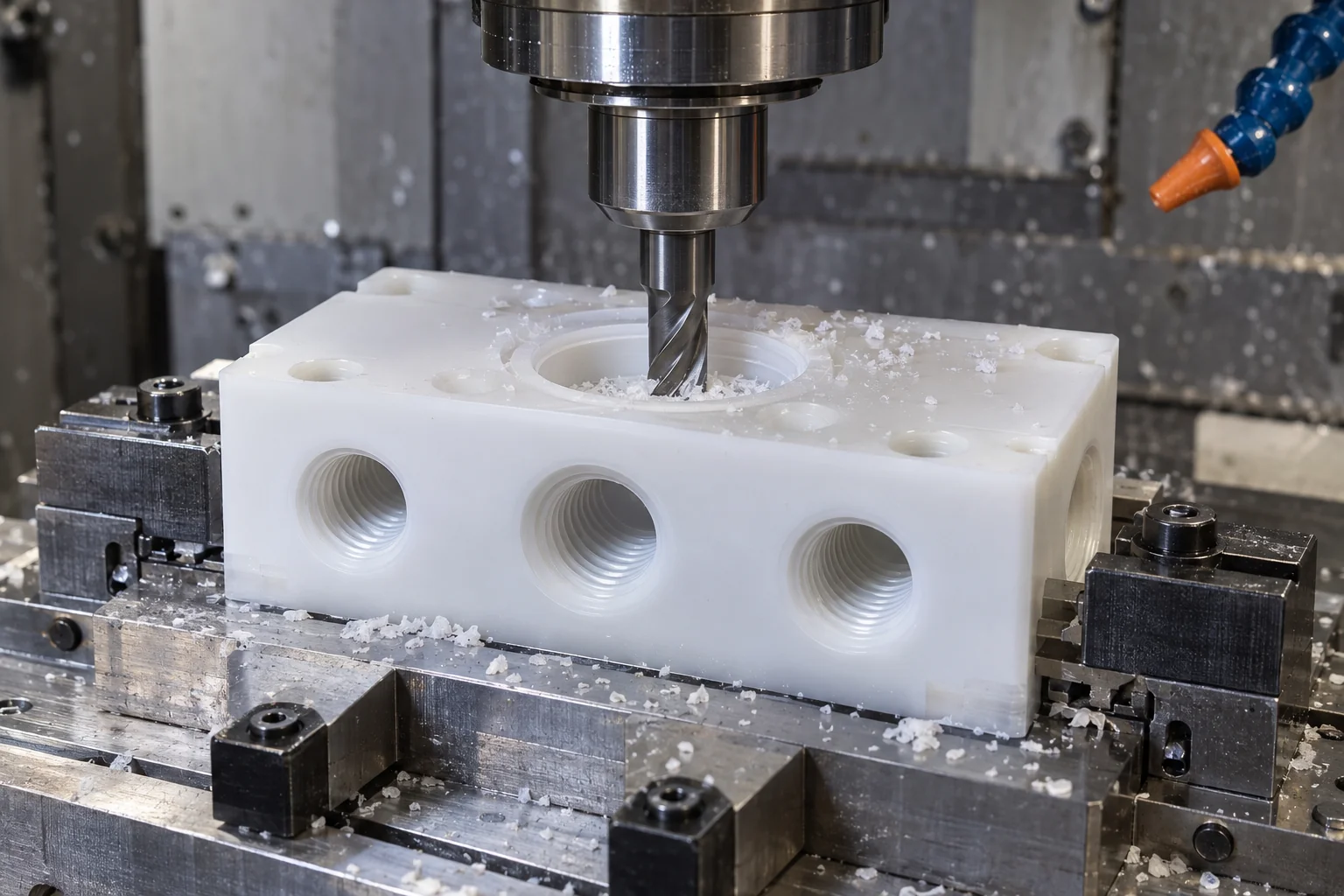
Machine the manifold body, pockets, mounting faces and sealing surfaces with suitable support and controlled stock removal.
Create internal passages within agreed reach and aspect-ratio feasibility. Plan intersections, chip evacuation and closure openings.
Produce the specified port thread and controlled engagement depth, protecting adjacent sealing features.
Use multi-axis access for angled or multi-face ports where geometry justifies the process.
Address accessible burrs and residual chips using a method compatible with the polymer and project requirements.
Check drawing dimensions, port relationships, threads and sealing faces; special functional tests require a separately agreed plan.
Acrylic / PMMA and Polycarbonate can provide visual access to channels, bubbles and visible contamination when the medium and operating duty suit the selected grade.
Observe fluid routing and bubbles during development and troubleshooting with a documented material and cleaning plan.
Make internal passages visible without opening the block. Visual inspection supports understanding but does not measure flow rate.
Acrylic may craze, whiten or crack under residual stress, unsuitable solvents or poor finishing. Polycarbonate also needs chemical stress-cracking review.
Specify viewing faces, acceptable tool marks and clarity. Polishing, bonding and pressure suitability are separate requirements.
Use the required transparency only where it adds value. Transparent appearance is not evidence of pressure capability, validated cleanliness or medical suitability.
Consider plastic when chemical resistance, purity requirements, lower mass, isolation or transparency are central. Metal is often more suitable when very high pressure, temperature or structural stiffness dominates.
| Factor | Plastic manifold | Metal manifold |
|---|---|---|
| Weight | Generally lower for a comparable block | Generally higher, depending on alloy and geometry |
| Corrosion resistance | Useful options when grade and medium are compatible | Depends on alloy, fluid and surface condition |
| Electrical isolation | Available in appropriate insulating grades | Generally conductive; isolation needs a separate design |
| High-purity options | Specified-grade PVDF / PTFE and controlled processes may suit | Suitable alloy, surface treatment and cleaning may suit |
| Very high pressure | Limited by creep, geometry, temperature and fitting loads | Often higher strength and stiffness; still requires validation |
| Temperature capability | Grade- and duty-dependent; derating may be necessary | Often higher, subject to alloy and seals |
| Transparent options | Available in Acrylic and Polycarbonate | No direct optical access through the block |
| Chemical resistance | Select from compatible polymer families and grades | Select the appropriate alloy or protective treatment |
Match the manifold to the equipment’s fluid circuit and documentation requirements rather than choosing a material from the industry name alone.
PVDF, PEEK and PTFE candidates for chemical-delivery or wet-process systems, with agreed purity and handling requirements.
PVC, CPVC, PP and fluoropolymer options for specified process mixtures; confirm grade availability and chemical compatibility.
Transparent or chemically resistant sample-routing blocks where dead volume, cleaning and carryover matter.
Precision fluid-routing components using documented grades and project-specific validation; no blanket medical approval is implied.
Dosing and distribution blocks with compatible wetted materials, seals and cleaning methods.
Pneumatic and coolant distribution blocks with controlled fittings, mounts and circuit connections.
Only where the exact grade and complete wetted assembly have the documentation and suitability required for the intended contact.
Agree dimensional acceptance and the internal-channel verification plan before manufacture. Functional leakage or pressure acceptance requires an explicit test specification.
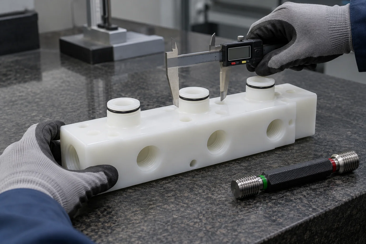
Check the specified polymer, purchased grade and required traceability documents.
Confirm revision, circuit connections, isolated branches and closure strategy.
Check specified port locations, orientation, engagement and appropriate thread-gauge requirements.
Review intended intersections and accessible evidence of continuity using the agreed method.
Check gland dimensions, specified finish and sealing-face flatness.
Verify mounting geometry and relevant datum relationships.
Evaluate accessible passages and the agreed burr / cleanliness acceptance criteria.
Confirm test availability, provider, medium, pressure or vacuum, hold time, leak limit, safety method and report before accepting the test requirement.
Protect threads, seals and passages using the agreed handling and packaging requirements.
Dimensional inspection does not establish a pressure rating or a leak-free assembly. Leak testing, pressure testing, cleanroom handling and validated cleanliness protocols are only included when scope and capability have been explicitly agreed.
Use early parts to review port access, assembly fit, sealing and fluid behavior before freezing a repeat-production revision.
Review layout, closures and mating fittings; validate fluid paths and assembled performance with a defined test plan.
Support specialized equipment and evolving designs with controlled revisions and agreed inspection requirements.
Maintain the agreed grade, machining program, port map, drawing revision and inspection plan across recurring orders.
A manifold’s performance depends on the complete fluid system: material compatibility, port geometry, seals, internal passages, burr control, pressure, temperature and cleanliness all need to work together.
Manufacture against the approved model, drawing and fluid-circuit intent.
Discuss exact-grade selection against the medium and operating conditions.
Review multi-port blocks and cross-drilled circuits for machining access.
Focus inspection on the interfaces that connect and seal the assembly.
Machine O-ring grooves and installation geometry to defined requirements.
Develop the part and preserve the approved revision for recurring orders.
Discuss viewing faces and suitable finishing for Acrylic or Polycarbonate designs.
Agree critical dimensions and the acceptance evidence needed for the project.
Practical answers about manifold materials, threads, pressure, seals and internal passages.
A plastic manifold is a block or plate containing ports and internal passages that route, distribute, combine or isolate liquids, gases or vacuum within equipment. The port map, seals and material are specified for the intended circuit.
The best material depends on the medium, concentration, pressure, temperature, purity and mechanical duty. PVDF, PEEK, PTFE, PVC / CPVC, PP, Acrylic, Polycarbonate and POM each offer different tradeoffs; select the exact grade and compatible seals together.
PVDF can be preferable when greater stiffness and dimensional support are useful alongside suitable chemical resistance. PTFE offers very broad chemical resistance but needs more attention to creep and low stiffness. Compare exact-grade compatibility and the assembled service conditions.
Yes, when the specified thread, fitting and sealing method suit the plastic body. Define NPT, BSPP or BSPT explicitly, with size, engagement, wall thickness and an approved installation method; these thread forms are not interchangeable.
Yes, suitable designs can operate under pressure, but there is no universal pressure rating for a machined plastic block. Grade, temperature, wall and port geometry, closures, fittings, creep and service life must be evaluated and the assembly validated for its intended duty.
O-ring grooves are machined to the specified gland geometry, including width, depth, corners and surface condition. Seal selection and required squeeze / gland fill depend on the mating parts, medium, pressure and temperature; no single groove suits every seal.
Yes, where the exact grade is compatible with the medium, pressure, temperature and cleaning cycle. Define viewing faces and clarity, and assess stress cracking, residual machining stress and any polishing or joining process.
Burr control starts with machining sequence and accessible channel design, followed by suitable deburring and compatible cleaning. Hidden intersections need an agreed verification method; complex inaccessible passages may require a design change before acceptance can be confirmed.
Port positions and angles, thread depth, O-ring glands, sealing-face flatness, cross-channel alignment and minimum walls are usually the key features. Specify critical relationships and the inspection condition rather than one tight tolerance for every surface.
Yes, send the model, drawing or sample for a feasibility review. A sample may not reveal hidden routing, original material, pressure rating or sealing intent, so the fluid circuit, service conditions and acceptance drawing must be confirmed before manufacture.
YOUR CIRCUIT. YOUR MEDIUM. YOUR OPERATING DUTY.
Upload your manifold drawing or CAD model and include the material, quantity, port layout and thread types, medium, operating pressure, temperature, sealing method and cleanliness requirements. Our team can review machining access and the inspection scope before quotation.
Company, name, email and phone are required. Country, part number, quantity and drawing upload are optional. Put the engineering details in your drawing package or email; no long technical form is needed.
info@tops-precision.comSTEP / STP / IGES / X_T / DWG / DXF / PDF or ZIP, maximum 10 MB. Larger packages can be shared by email. Agree confidential-file handling before sending sensitive drawings.