
High Impact Resistance
Useful for tough covers and components; verify impact performance for the specified grade, geometry and hazard.
CLEAR VIEWS. CONSIDERED ENGINEERING.
TOPS Plastics manufactures custom Polycarbonate components to your CAD files and engineering drawings. From transparent machine guards and inspection windows to precision housings and structural parts, we review the grade, geometry and acceptance requirements before quoting.
CNC machining, milling, turning, routing and cutting form the core process review. Polishing, forming, bonding and assembly are assessed for the specific grade and part.
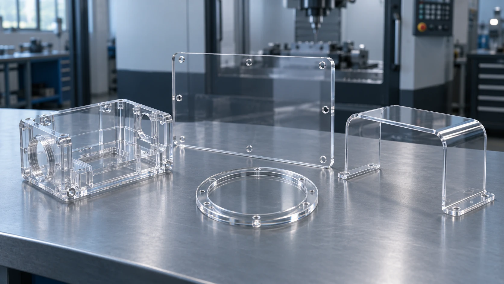
Start with the exact stock grade, drawing revision and acceptance requirements. Process availability and numerical capabilities are confirmed for your project.
| Review item | Project scope |
|---|---|
| Material | Polycarbonate (PC); identify supplier grade, color, coating and stock form. |
| Processes | CNC milling, turning, multi-axis machining, routing and cutting; forming, polishing and assembly subject to feasibility review. |
| Part types | Guards, windows, covers, housings, panels, fixtures and precision components. |
| Stock forms | Sheet, plate, rod or suitable blanks; procurement and grade availability require confirmation. |
| Grade options | Clear, optical, UV-stabilized, flame-retardant, filled or dissipative formulations where suitable machinable stock is available. |
| Production | Prototype, low-volume and repeat orders with an agreed inspection plan. |
| Drawing files | STEP / STP, IGES, X_T, DWG, DXF and PDF; include units and revision. |
| Inspection | Dimensional checks and visual or optical acceptance criteria agreed before manufacture. |
Polycarbonate is an amorphous thermoplastic widely used where toughness and, for suitable grades, transparency are important.
Clear PC can combine a useful viewing surface with mechanical strength and impact resistance. It is used for equipment windows, covers and engineering components that need a different balance of properties from acrylic or opaque wear plastics.
Material selection must consider the actual grade, thickness, stress, temperature, UV exposure and chemicals. A resin family name does not establish safety performance, regulatory approval or an optical specification.
Technical references: Ensinger TECANAT natural material guidance
Match each advantage to the operating conditions rather than choosing by material name alone.
Useful for tough covers and components; verify impact performance for the specified grade, geometry and hazard.
Clear grades support viewing windows. Machined areas may need separate clarity and cosmetic requirements.
Suitable for structural interfaces when loads, deflection and long-term behavior are reviewed.
Temperature capability is grade- and load-dependent. Check sustained service conditions, not only a short-term material value.
Specify the electrical environment and required documentation. Conductive or dissipative grades behave differently.
CNC processes create precise features, but heat, clamping and residual stress require deliberate control.
These are selection categories for discussion, not a statement that every grade is stocked or supplied in every sheet or rod size.
A starting point for clear guards, covers and components, subject to the stock datasheet and environment.
Discuss transmission, haze and distortion limits. Resin optical properties do not guarantee a finished machined optical part.
Consider outdoor exposure, life expectations and whether UV protection is integral or a surface layer.
Specify the exact grade, thickness and applicable rating. A rating from another formulation cannot be transferred.
Reinforcement changes stiffness, machining and appearance. Filled grades generally do not provide clear viewing surfaces.
Specify the required resistance range and test conditions. Confirm suitable stock and documentation before quoting.
Supplier resin designations and machinable stock availability are different questions. Confirm that the required formulation, color, coating and traceability can be supplied in an appropriate blank.
Technical references: Covestro Makrolon grade information
Choose a process around geometry, viewing areas and assembly interfaces. We review the complete drawing before agreeing the route.
Pockets, bores, slots, mounting features and coordinated datum surfaces.
Explore this service →Circular windows, collars, light-guide blanks and rotational features.
Explore this service →Angled features and multi-face access where the geometry benefits from controlled orientation.
Explore this service →Profiles and openings in sheet components, with support and edge quality considered.
Prepare panels and blanks with allowances for subsequent finishing and inspection.
Discuss bends, radii and stock coating first. Availability and a suitable forming procedure must be confirmed.
Review joint design, adhesives, cleaner compatibility and retained stress; qualify the assembly method before production.
Protective film can help during handling, but heat-processing instructions may require its removal. Follow the specific sheet manufacturer’s fabrication guidance; do not assume that coated and uncoated sheet behave alike.
Technical references: Plaskolite TUFFAK fabrication guide
A dimensionally acceptable part can still have damaged viewing surfaces or retained stresses. Both matter.
Control engagement, tool condition and chip removal to limit local heating and surface damage.
Use clean supports, protected storage and separate handling for designated viewing faces.
Stock history and material removal can influence movement after machining. Agree when reinspection is needed.
Review internal radii and load paths to avoid unnecessary stress concentrations.
Keep chips away from finished faces and prevent recutting that can mark edges or surfaces.
Define where a person must see through the part and where the drawing only requires a functional machined feature.

Identify the viewing zone and agreed transmission, haze or distortion method if those values are important.
Define lighting, viewing distance and acceptable scratches or tool marks using an agreed reference or specification.
Bores, threads and mounting faces may have visible tool marks while meeting their dimensional function.
Specify whether edges are simply deburred, finely machined or require a validated clarity finishing process.
Machining does not automatically produce optical clarity. A clear original sheet face and a newly machined pocket may look very different. Agree acceptance samples or a first article before committing to repeat production.
Send Your Optical and Cosmetic Requirements →Tolerance feasibility depends on geometry, stock, wall thickness, temperature, stress and how the feature will be measured. We do not apply one universal tolerance to all PC parts.
| Feature | What to define |
|---|---|
| Flat panels | Flatness, free-state support, thickness and inspection temperature. |
| Thin walls | Permitted deflection and how the part is supported during measurement. |
| Clear housings | Datum scheme, wall balance, viewing zones and assembly interfaces. |
| Precision bores | Mating dimensions, fit, gauge method and thermal conditions. |
| Large guards | Hole locations, mounting clearances and thermal expansion allowance. |
| Multi-face features | Datums and relationships between holes, pockets and mounting faces. |
| Optical surfaces | Optical/cosmetic acceptance separately from dimensional tolerances. |
| Threads | Designation, engagement, assembly torque and inserts if required. |
Residual stress, machining heat and assembly loads can interact with the environment. Review them as a connected system.
Material history and uneven stock removal can affect dimensional stability. Discuss staged machining and release checks.
Local heating can affect the surface and dimensions. Measure after an agreed stabilization period where necessary.
Support the component without forcing it into a shape that changes when released.
Certain cleaners, adhesives or chemicals can promote cracking in stressed PC. Verify compatibility at actual exposure conditions.
Annealing or other stress-management steps are considered only when the grade, geometry and manufacturer guidance support them. Agree the procedure and reinspection requirements; a generic heat treatment is not a substitute for a qualified process.
Your drawing should separate functional fits, viewing zones and cosmetic expectations.
Mark faces that must remain clear and whether machining is permitted in those zones.
Allow cutter access and avoid unnecessary sharp load-bearing corners.
Review thin sections, support and uneven material removal before fixing tight requirements.
Define installation clearances for the panel size and temperature range.
Specify protection during handling and follow film-removal requirements for the chosen process.
Apply tight limits to functional features, with datums and measurement conditions.
Review fasteners, washers, inserts, torque and support; avoid forced fits.
Include UV, chemicals, cleaning agents, temperature and exposure duration.
These distinct illustrations show component concepts for drawing review, not catalog products or verified customer projects.
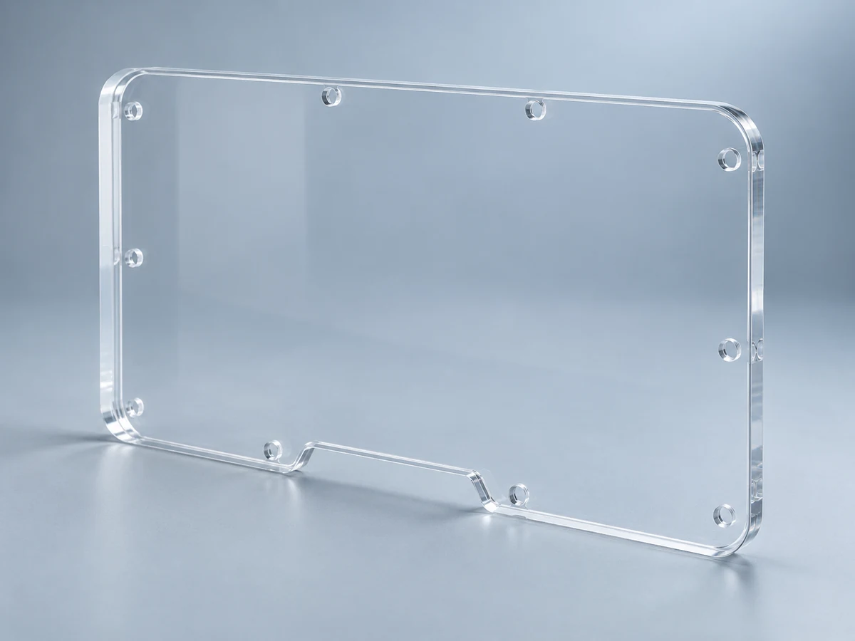
Clear panels with mounting features; the guard design must address the specific machine hazard.
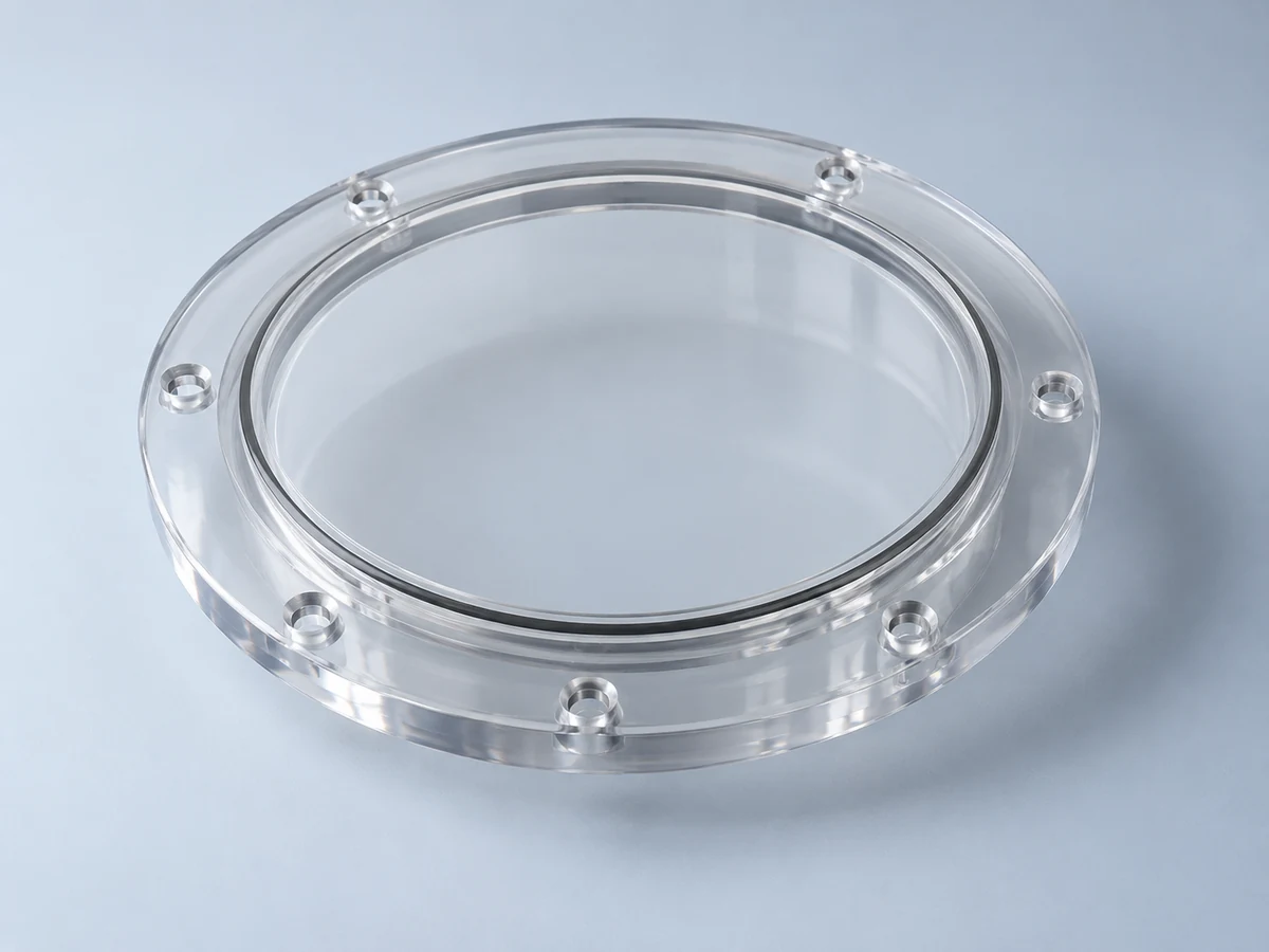
Viewing zones and mounting holes with agreed cosmetic and dimensional acceptance.
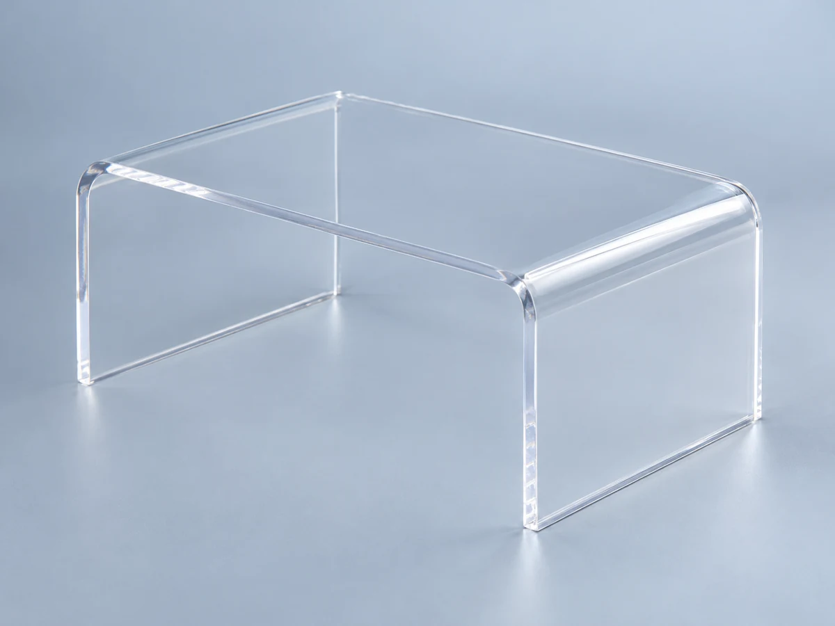
Shaped covers with practical bend radii, clearances and protected handling.
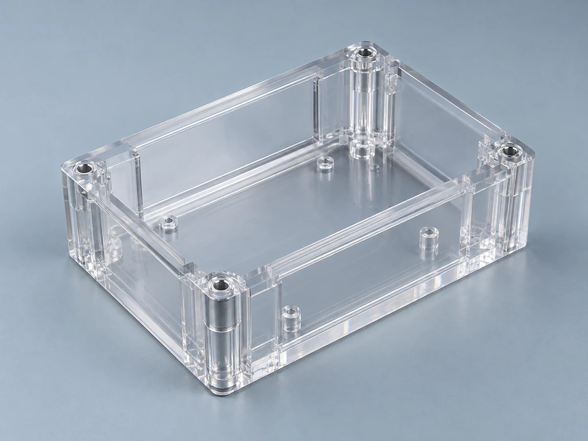
Pockets, walls and mounting interfaces reviewed together with viewing areas.
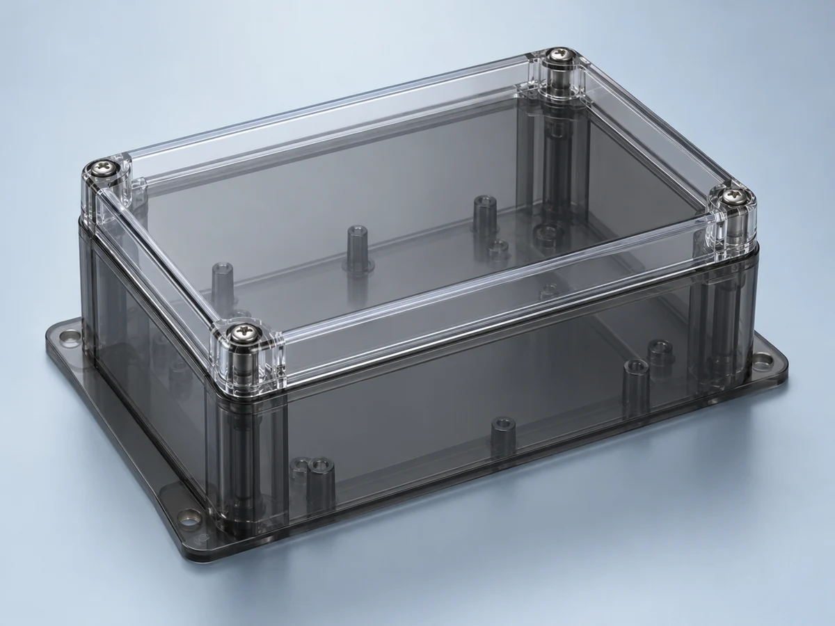
Enclosure bodies and lids with coordinated mounting and access details.
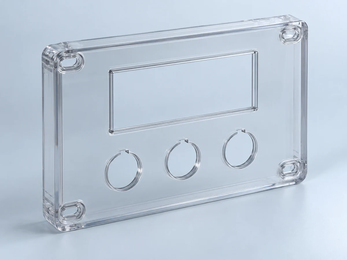
Display openings, switch holes and routed contours for equipment interfaces.
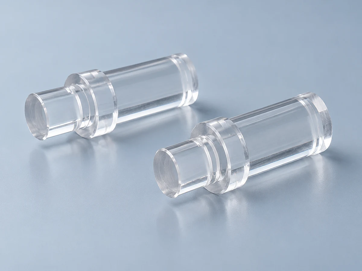
Light-path geometry with explicitly agreed optical acceptance and finishing.
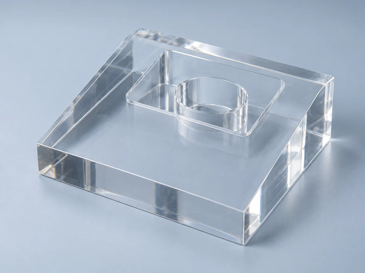
Transparent blocks with defined faces, edges and clarity expectations.
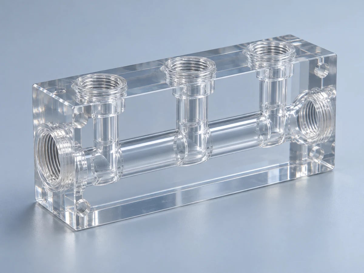
Drilled passages and sealing interfaces subject to fluid, pressure and compatibility review.
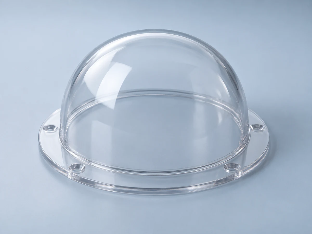
Viewing covers with mounting features and installation clearance.
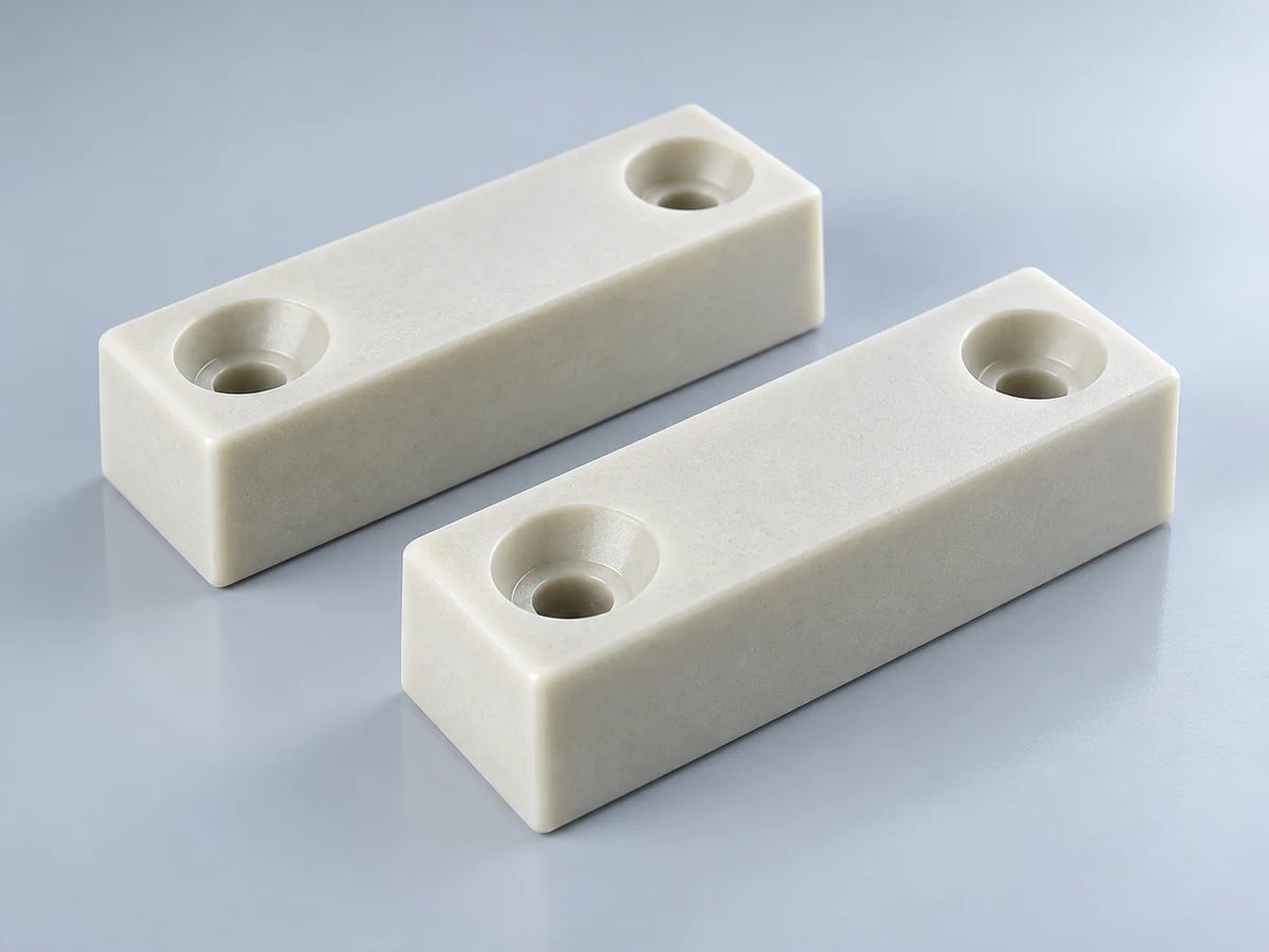
Grade-specific electrical components; illustration shows an opaque filled formulation.
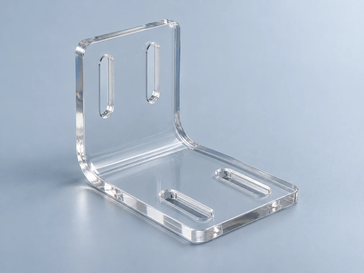
Mounting angles, slots and support features with load and assembly review.
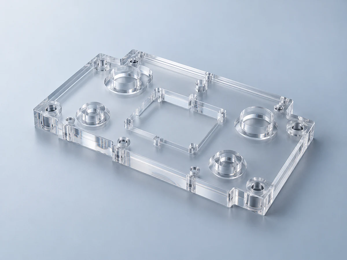
Locating pockets and mounting patterns for inspection or production equipment.
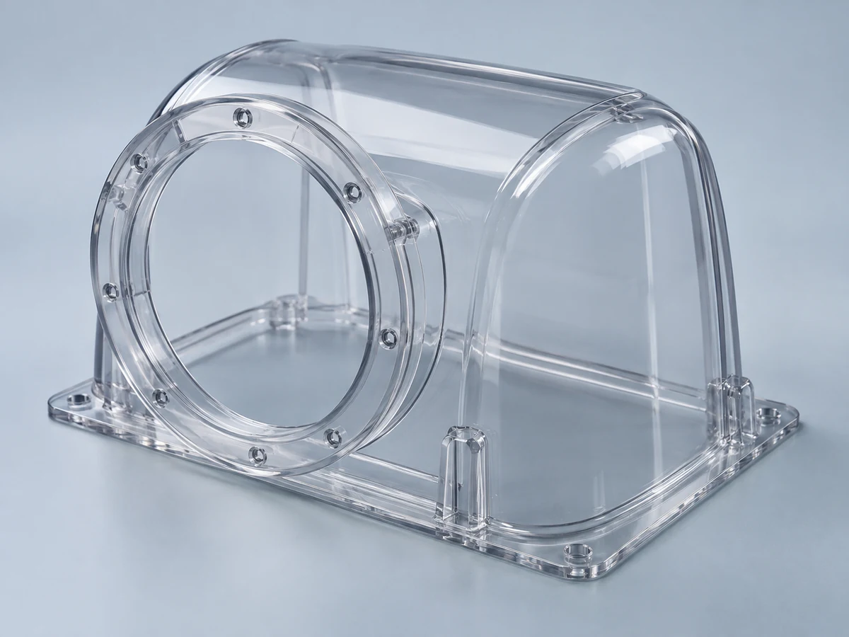
Equipment covers and interfaces; suitability and regulatory documentation require project confirmation.
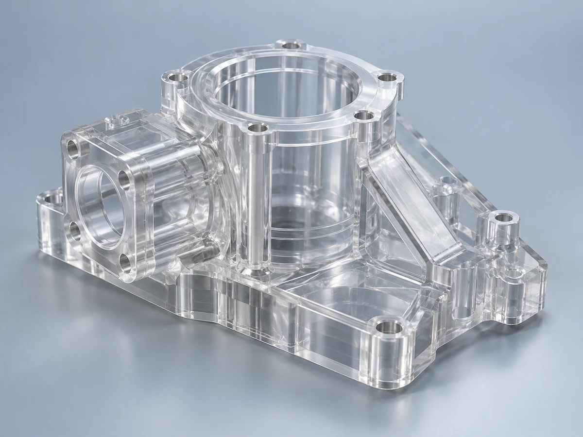
Multi-face geometries produced to the specified drawing and acceptance plan.
Polycarbonate is a material option for guards and viewing panels. The complete safeguard must be designed and validated for the machine and hazard.

Viewing panels around machining zones; specify fragment hazards, supporting frame and retention.
Clear interfaces around robotic cells; review the complete protective enclosure and mounting arrangement.
Door panels with access hardware; account for repeated motion, hinges and frame support.
Windows positioned for a defined viewing zone, with mounting holes and cleaning compatibility.
Panels to contain specified splashes; identify fluid, temperature and cleaning agents.
Equipment covers with customer-defined protective performance and installation requirements.
Transparent openings in housings; define sight lines, cosmetic acceptance and fit.
Material selection alone does not establish an impact rating or a compliant machine guard. The responsible equipment designer must specify the hazard, required performance and verification. Include fragments, projectile energy, temperature, chemicals, fasteners and support conditions where relevant.
Installation preparation should include clean supports, approved fasteners and cleaners, and room for expansion. Do not force a distorted panel into its frame or transfer an unverified guard thickness from another machine.
Specify the result you need rather than assuming that every machined face will be glass-clear.
Visible tool marks may be acceptable on non-viewing functional features.
Discuss cutter access and an achievable surface condition for the specific geometry.
Request an edge appearance review. The method and resulting dimensions must be validated.
An additional finishing route may be needed; confirm feasibility, test method and acceptance before quoting.
We do not promise glass-like clarity or a particular vapor-polishing method without process validation. Finishing can affect geometry, surface condition and retained stress; include these considerations in the first-article approval.
Agree dimensional, visual and any optical checks before manufacture. A visual photograph alone does not establish conformance.
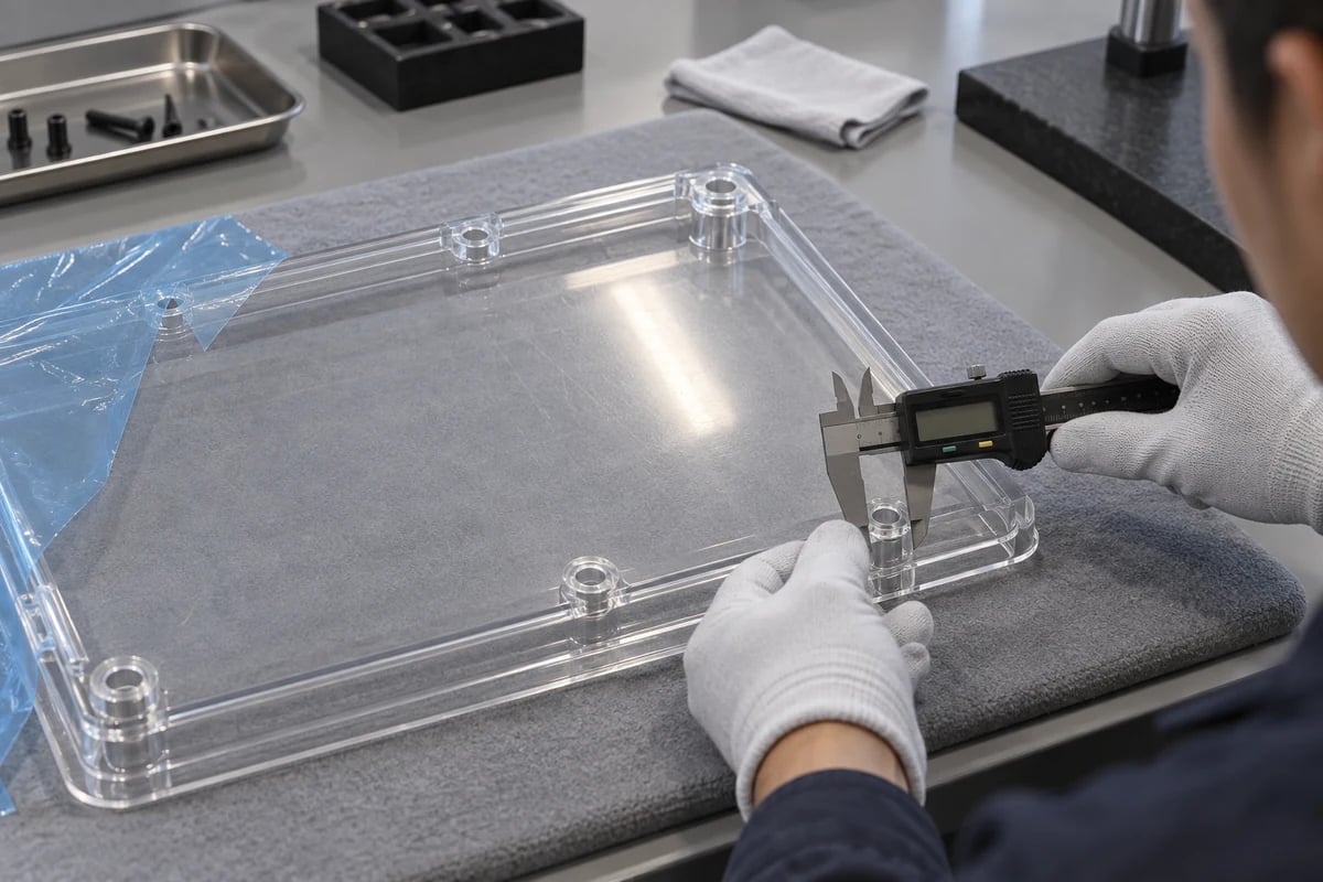
The plan may cover hole position, thickness, flatness, profile, bores, mounting patterns, scratches, transparency and edge condition. Define the equipment, sampling, environmental conditions and reporting needed for your project. Shipment inspection should check protective packing as well as the finished component.
Choose PC when toughness and impact resistance lead the decision. Consider acrylic when visual appearance and surface hardness are more important and the load conditions permit it.
| Factor | Polycarbonate (PC) | Acrylic (PMMA) |
|---|---|---|
| Impact resistance | Often preferred for tough protective components; verify grade and geometry. | Typically more brittle; review the risk of impact and cracking. |
| Clarity | Clear grades available; machining and finishing influence the result. | Often selected for clear display and appearance parts; verify optical specification. |
| Scratch resistance | Uncoated surfaces can scratch; hard coatings change the comparison. | Generally harder than uncoated PC, but still requires protected handling. |
| Toughness | Useful for loaded covers and mechanically demanding interfaces. | Choose with care for concentrated loads and forced assembly. |
| Machining | Heat, stress and viewing-face protection need control. | Tooling, chipping and brittle edges require attention. |
| Machine guards | A frequent material option; the complete safeguard still needs validation. | Suitability depends on hazard and specified performance. |
| Appearance parts | Useful where appearance must be balanced with toughness. | A common choice for polished visual and display components. |
| Formability | Grade, coating and forming procedure matter. | A different forming process window; consult the stock supplier. |
Technical references: PLEXIGLAS guidance on scratch resistance
Each material solves a different application problem. Compare the exact grade and operating environment.
| Material | Typical selection reason | Review before choosing |
|---|---|---|
| Polycarbonate | Tough clear components and equipment viewing parts. | Chemical compatibility, scratches, stress and optical acceptance. |
| Acrylic / PMMA | Clear appearance and display parts. | Impact loads, brittle edges and assembly stress. |
| Delrin / POM | Opaque mechanical parts, fits and sliding interfaces. | Grade, wear duty and chemical exposure. |
| Nylon | Wear components, rollers and loaded mechanical parts. | Moisture conditioning, dimensional changes and service humidity. |
| PEEK | Demanding thermal or chemical applications. | Grade, cost and required documentation. |
| ABS | Often opaque housings and general engineering prototypes. | Exact formulation, temperature, chemicals and appearance; properties vary. |
The application sets the acceptance requirements. The material family alone does not establish regulated-use suitability.
Viewing panels, covers and equipment housings with mounting and cleaning requirements.
Clear protective interfaces, panels and fixtures with load and installation review.
Instrument covers and equipment interfaces; confirm grade, cleaning and regulatory requirements.
Housings, panels and insulation parts with grade-specific electrical and flame requirements.
Viewing covers and instrument components with chemical and optical specifications.
Fixtures and equipment parts reviewed for heat, load, UV and chemical exposure.
Transparent equipment interfaces with customer-defined purity, cleanliness and compatibility requirements.
Use early parts to validate more than dimensions: viewing quality, assembly stress and the operating environment also matter.
Check fit, transparency, installation and functional geometry. Validate impact or environmental performance with the responsible designer.
Approve the stock grade, process and cosmetic reference, then define inspection and packaging.
Control drawing revision, stock substitutions, process changes and acceptance records across orders.
Our quotation review connects the drawing, intended use and acceptance plan. Specific capabilities, documents and delivery terms are confirmed for each order.
Select a practical manufacturing route for the complete component.
Separate viewing surfaces from non-optical functional features.
Match the process to pockets, rotational details and sheet profiles.
Define handling and surface acceptance before production.
Review grade, geometry, stress and environmental compatibility.
Use approved first articles to support repeat manufacturing.
Build the inspection scope around customer requirements.
Quote the revision, quantity and documented scope rather than a generic catalog assumption.
A clear approval sequence reduces uncertainty between engineering, purchasing and manufacturing.
Direct answers to PC selection, clarity, machining, stress and protective applications.
Polycarbonate (PC) is an amorphous thermoplastic used for tough engineering components and, in suitable clear grades, viewing windows and covers. Select the exact grade for the application.
PC can be CNC machined, but heat, residual stress, chip control and surface protection need care. Feasibility depends on geometry and acceptance requirements.
Yes. Milling suits pockets, slots and multi-face details; turning suits circular features. The drawing and stock form determine the practical route.
Neither is best for every application. PC is often chosen for toughness and impact resistance; acrylic is often chosen for visual appearance and greater uncoated surface hardness.
Original clear faces can remain useful viewing surfaces if protected. Newly machined faces may show tool marks or haze, so define clarity requirements and any validated finishing.
Retained stress or assembly loads can interact with incompatible chemicals, cleaners or adhesives. Review actual grade, exposure and installation conditions.
We review tolerances against size, wall thickness, stock, datums, temperature and measurement method. Send the drawing for a feature-specific assessment.
It is a material option, but grade and thickness alone do not establish a compliant guard. The equipment designer must define the hazard, mounting and required verification.
Clear and specialty formulations may be considered where suitable machinable stock exists. Confirm the supplier designation, stock form and documents before quoting.
Send the drawing, viewing-zone requirements and quantity for review. Prototype scope should include fit, appearance and any application tests needed before production.
YOUR DRAWING. YOUR CLEAR REQUIREMENTS.
Upload your CAD model and drawing with the grade, quantity, critical tolerances and intended application. Identify transparent viewing zones and cosmetic requirements so our team can review the manufacturing route and quotation scope.
Include operating temperature, UV exposure, chemicals and cleaning agents. If the grade or process is undecided, describe the function and environment. All project details and drawing uploads are optional; company, name, email and phone are required.
info@tops-precision.comCAD and 2D drawing uploads: combined maximum 10 MB. Larger files can be shared by email. Agree confidential-file handling before sending sensitive drawings.