01
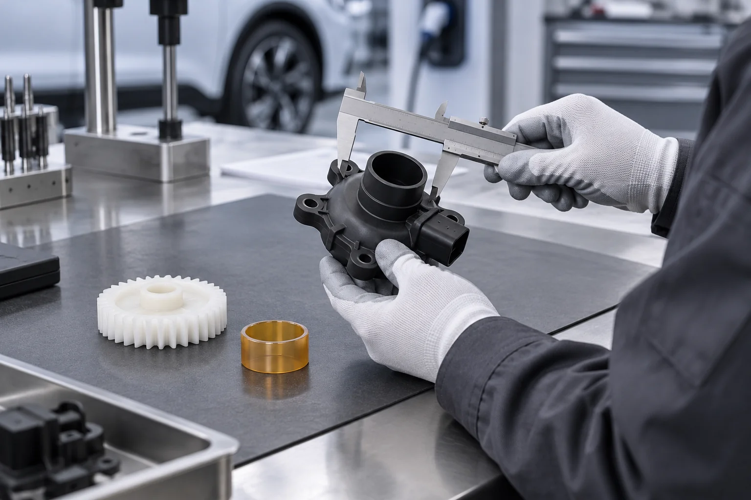
Plastic Housings
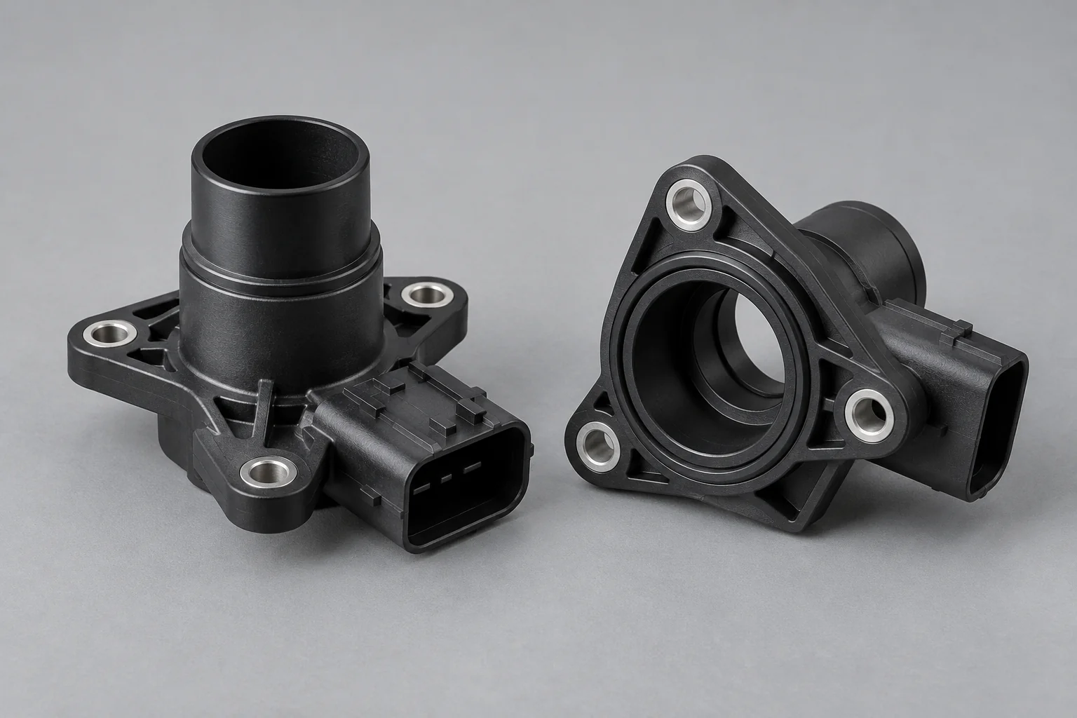
Sensor, control-unit, connector and actuator housings with defined mounting datums, bores and insert locations.
Explore component details →
AUTOMOTIVE SYSTEMS · EV DEVELOPMENT · PRECISION PARTS
TOPS Plastics manufactures custom CNC machined plastic components for automotive systems, electric vehicles, battery assemblies, sensors, fluid systems, interior equipment, production tooling and test equipment. We machine PEEK, POM/Delrin, Nylon, PTFE, PPS, PEI and other engineering plastics according to customer drawings, functional requirements and operating conditions.
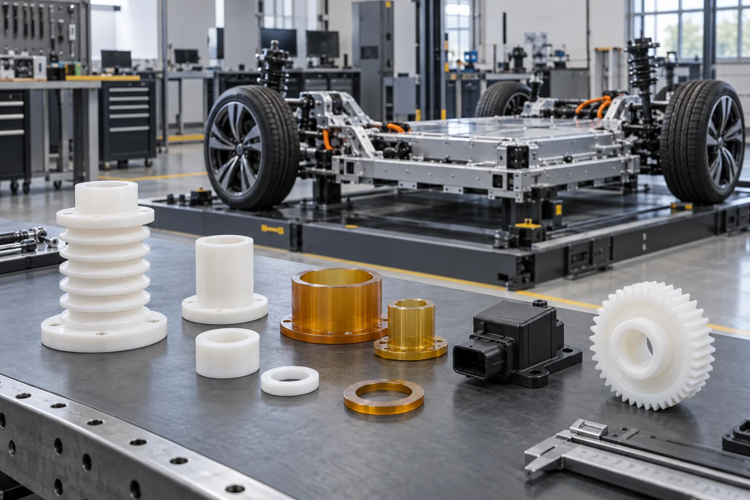
Connect the component to its vehicle system, production stage and functional acceptance requirements before selecting the process.
| Capability | TOPS Plastics |
|---|---|
| Typical parts | Housings, insulators, spacers, bushings, gears and fixtures |
| Materials | PEEK, POM, Nylon, PTFE, PPS, PEI and specified grades |
| Processes | CNC milling, turning, 5-axis machining, drilling and tapping |
| Key requirements | Weight, heat, wear, electrical insulation and chemicals |
| Production | Prototype, low-volume and repeat production |
| Input | STEP, CAD, 2D drawings and reference samples |
| Inspection | Drawing-based dimensional inspection |
| Documentation | Material and inspection documents where specified and available |
Connect each component to its vehicle system, exact material, operating environment and functional interfaces.
Sensor, control-unit, connector and actuator housings with defined mounting datums, bores and insert locations.
Explore component details →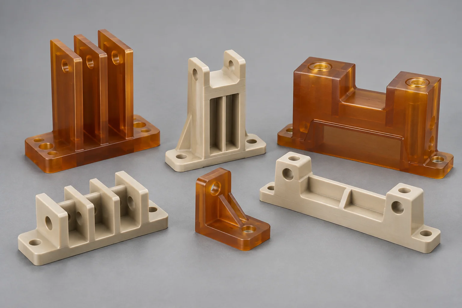
Battery, high-voltage assembly, connector and busbar isolation parts to customer-defined electrical and material requirements.
Explore component details →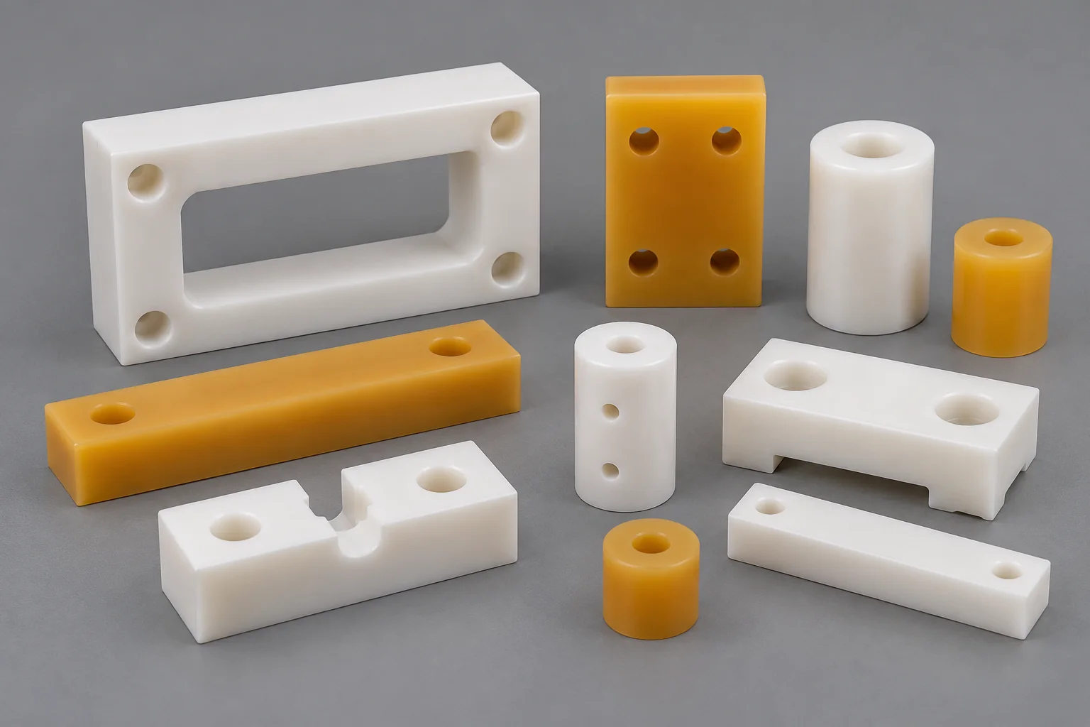
Battery-pack assembly, electrical isolation and structural stack components with controlled height and mating geometry.
Explore component details →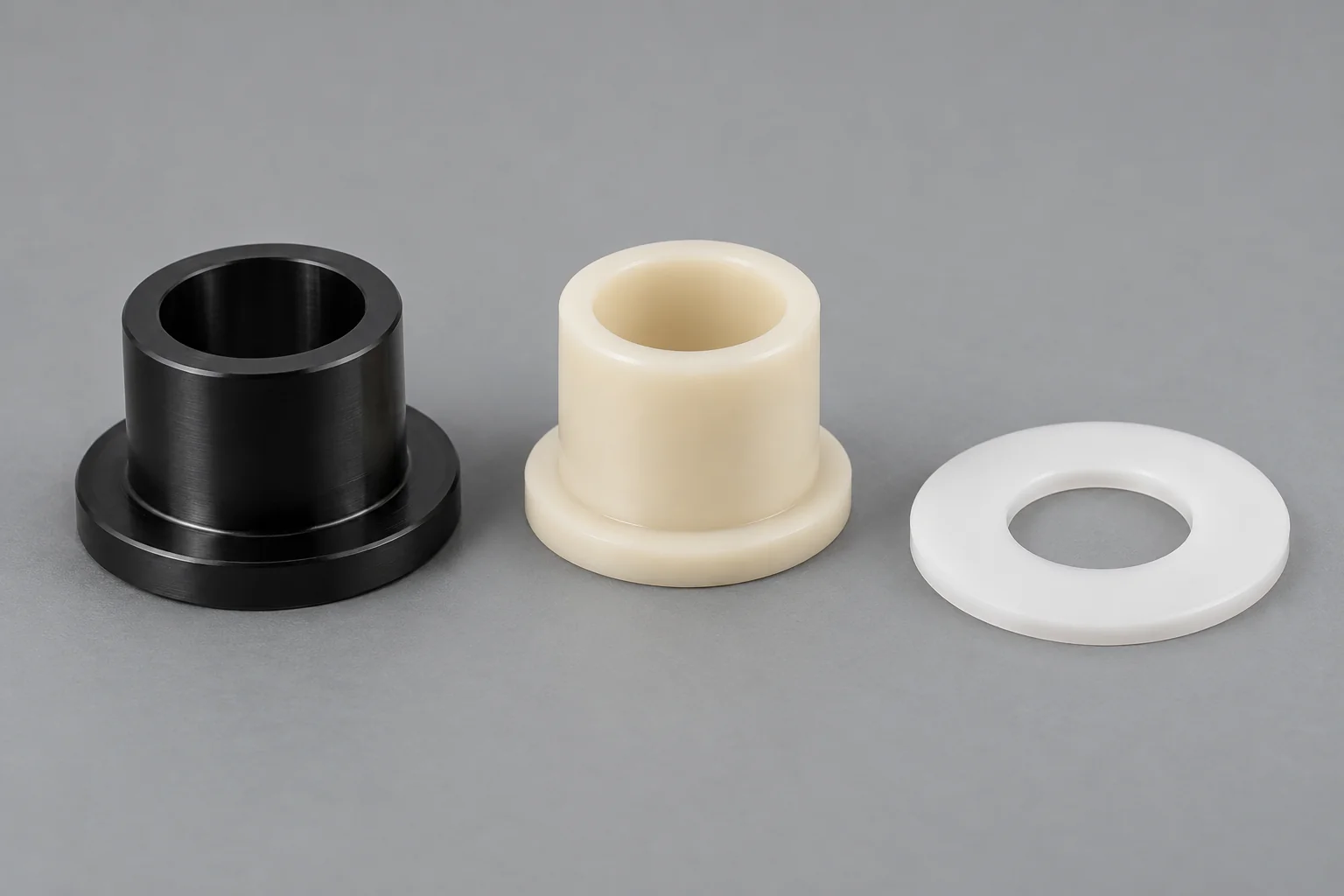
Pivot, actuator, seating and low-friction motion interfaces, matched to shaft, load, clearance and lubrication.
Explore component details →Plastic Bearings →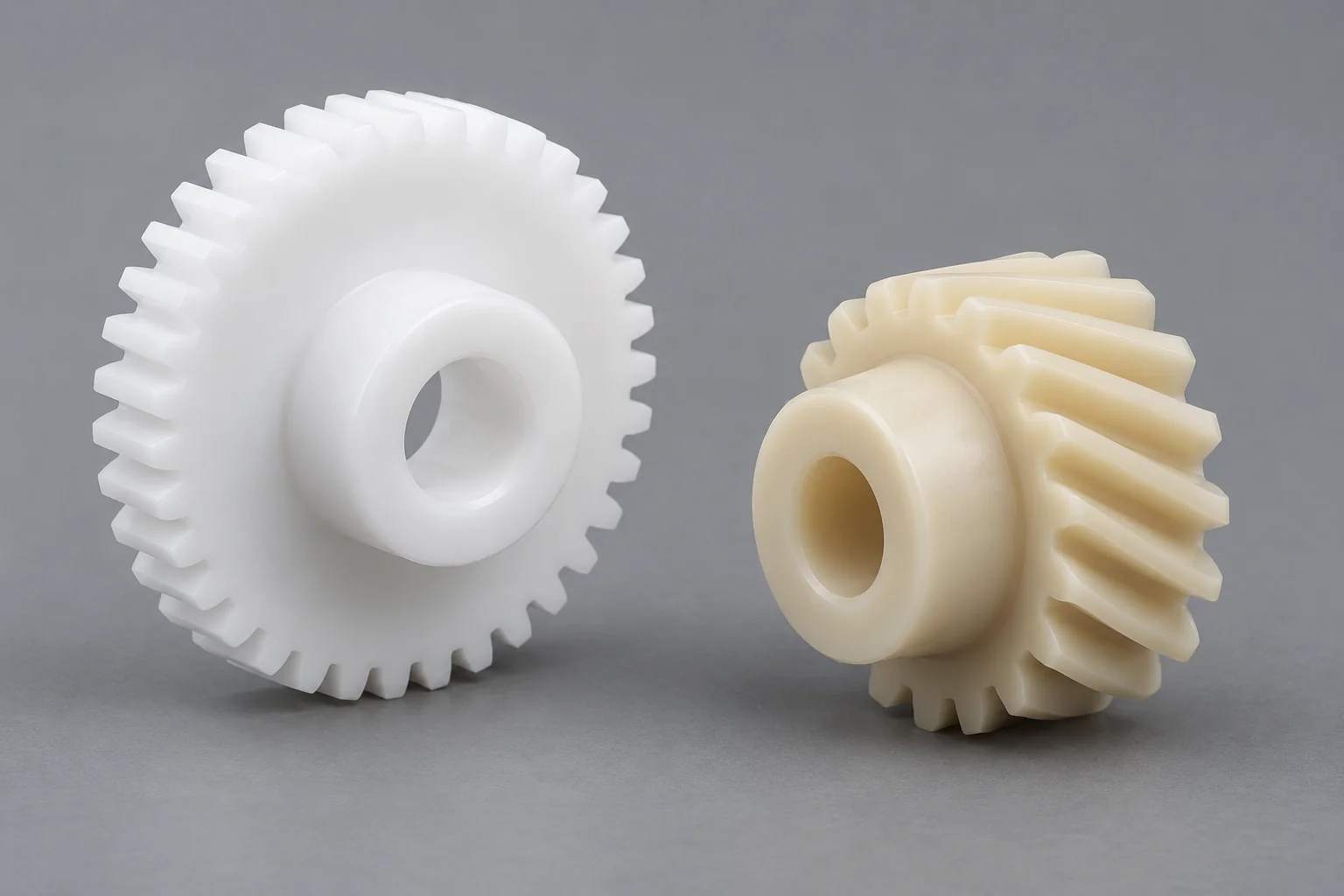
Actuator, seating, HVAC and interior-motion gears with specified tooth form, torque, backlash and mating parts.
Explore component details →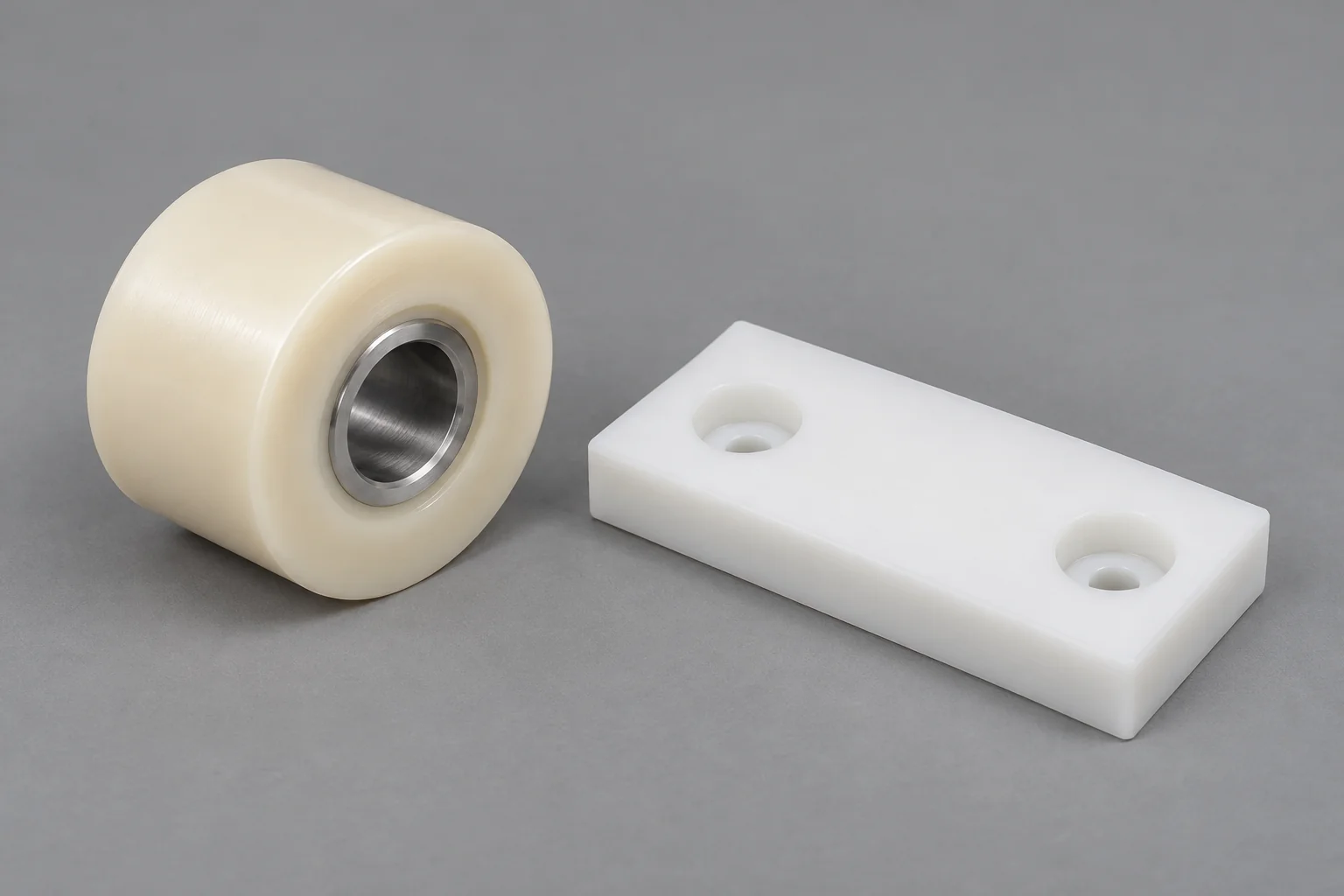
Guide, test-equipment and automated-assembly contact parts with defined runout, wear allowance and support.
Explore component details →Plastic Wear Pads →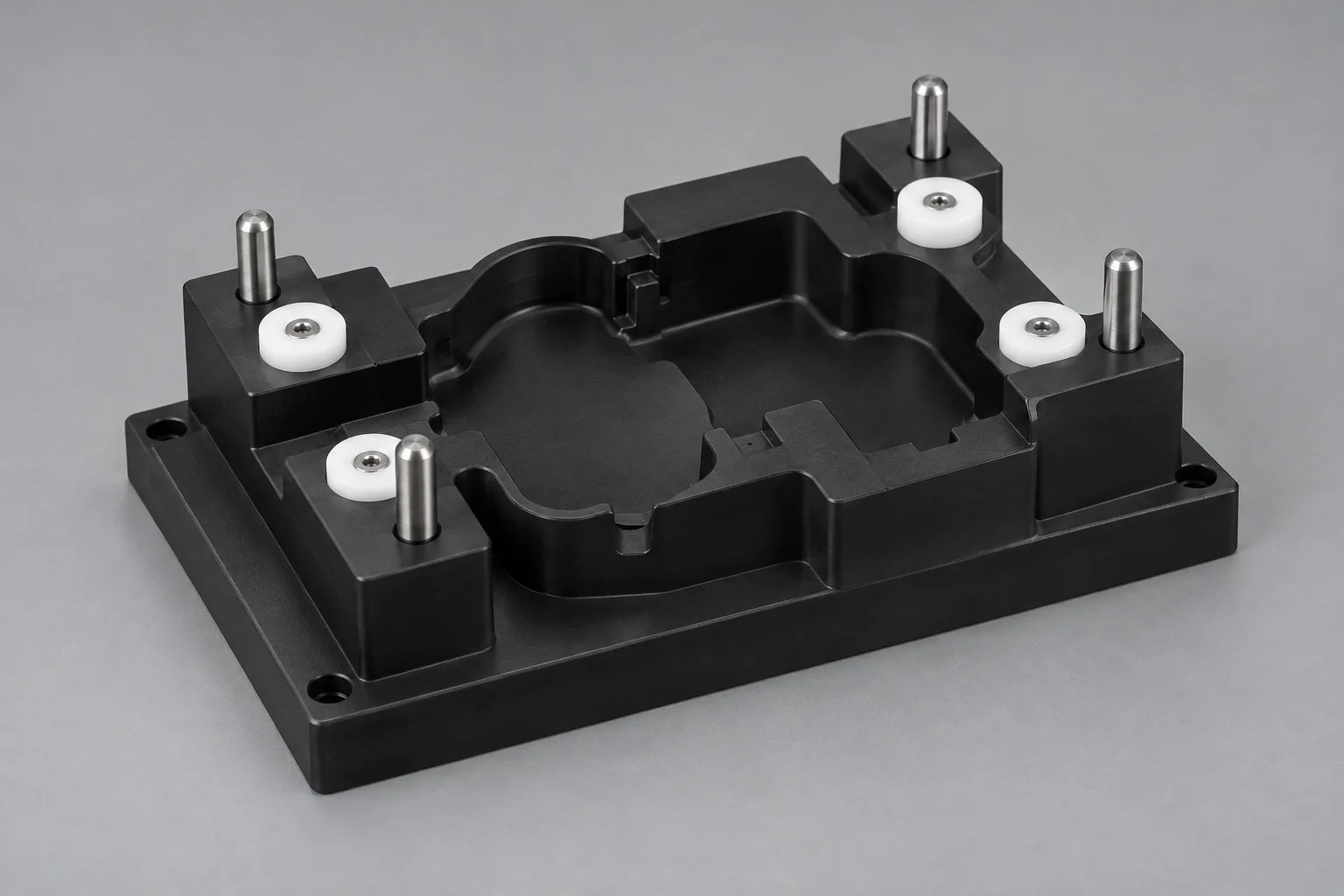
Assembly nests, inspection and test tooling, poka-yoke features and replaceable production-line contacts.
Explore component details →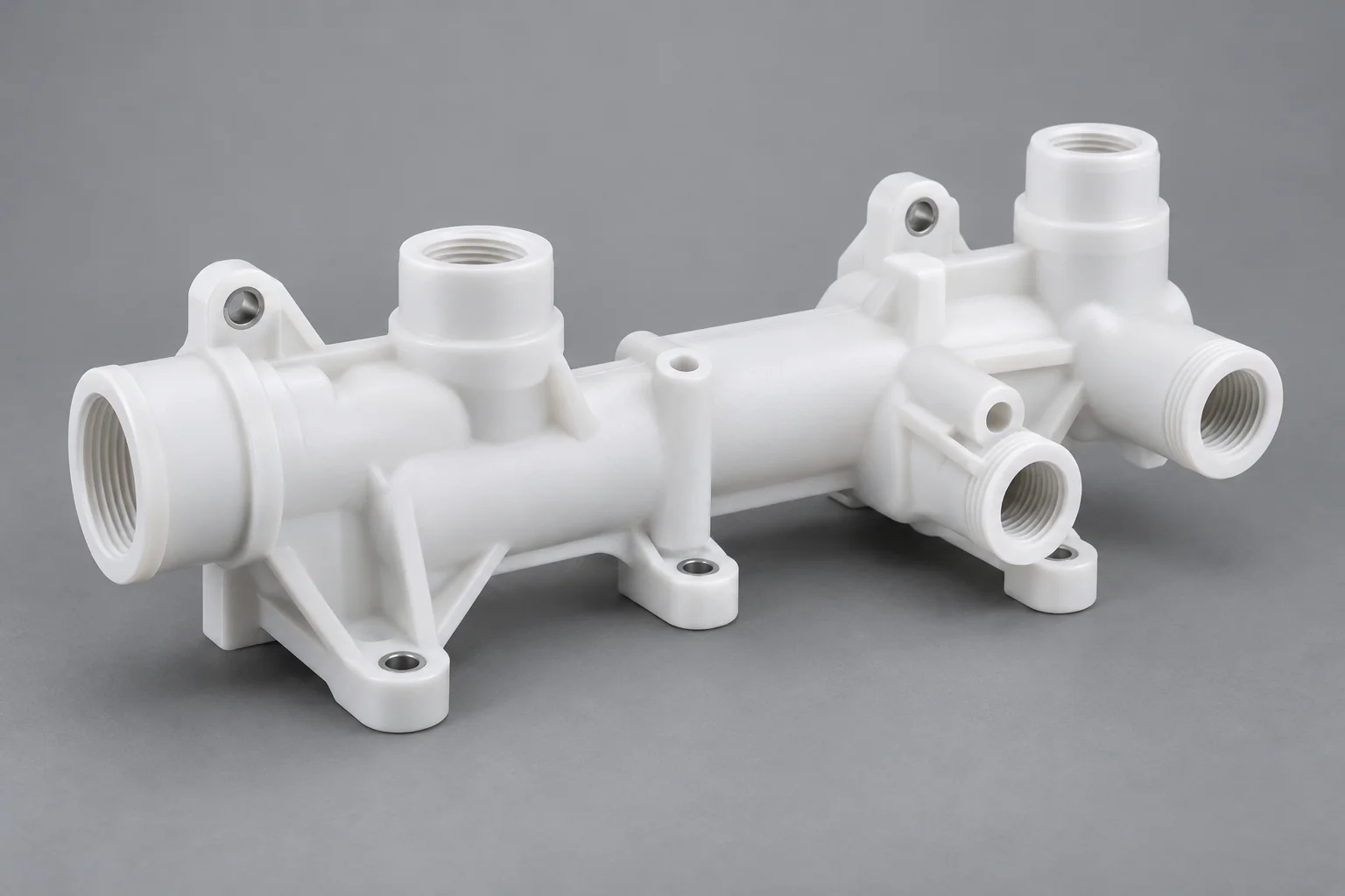
Coolant routing and test-system fluid blocks with released ports, seal features and operating conditions.
Explore component details →Vehicle system, part type and engineering need define the specification. Distinguish installed vehicle components from manufacturing or test tooling.
Insulating spacers, busbar supports, cell holders, connector supports, sensor housings and thermal-system interfaces require insulation, temperature stability, accurate fit and any specified flame performance.
Sensor and connector housings, spacers, insulating blocks and mounting features require electrical isolation, stable alignment, moisture review and suitable thermal behavior.
Gears, bushings, bearings, rollers and guides connect torque, speed, friction, wear and noise requirements within the mechanism.
Manifolds, valve parts, pump-related components, spacers and housings require coolant compatibility, pressure, temperature and defined seals.
Guides, spacers, housings, trim supports and actuator gears need suitable appearance, fit, mass, noise and environmental performance.
Jigs, fixtures, nests, inspection tooling and wear contacts locate parts through assembly and evaluation, with repeatable datums and replaceable interfaces.
There is no single best plastic. POM is a candidate for precision motion, Nylon for tough wear parts, PEEK for demanding heat or chemicals, and PPS or PEI for selected electrical and thermal duties.
| Material | Main advantage | Typical automotive use |
|---|---|---|
| POM / Delrin | Dimensional stability and useful low-friction behavior | Gears, guides and bushings |
| Nylon | Toughness and wear performance | Bearings, rollers and supported structural components |
| PEEK | Temperature, strength and chemical performance | Demanding EV and underhood components |
| PPS | Thermal and chemical stability | Electrical and underhood technical parts |
| PEI / Ultem | Electrical and thermal performance | Insulators and electronics supports |
| PTFE | Low friction and broad chemical compatibility | Sliding, sealing and isolation parts |
| UHMW | Wear, impact and low-friction contact | Production equipment and guides |
| Polycarbonate | Impact resistance | Covers and selected housings |
Compare exact grade, stock form, additives and supplier evidence against the customer specification. Filled grades can change stiffness, machining, wear and electrical behavior. Flame or electrical performance must be tied to the grade and relevant conditions rather than a general polymer name.
Insulating spacers, busbar supports, sensor mounts, battery fixture parts, connector housings, blocks and thermal-system supports need joint electrical and mechanical review.
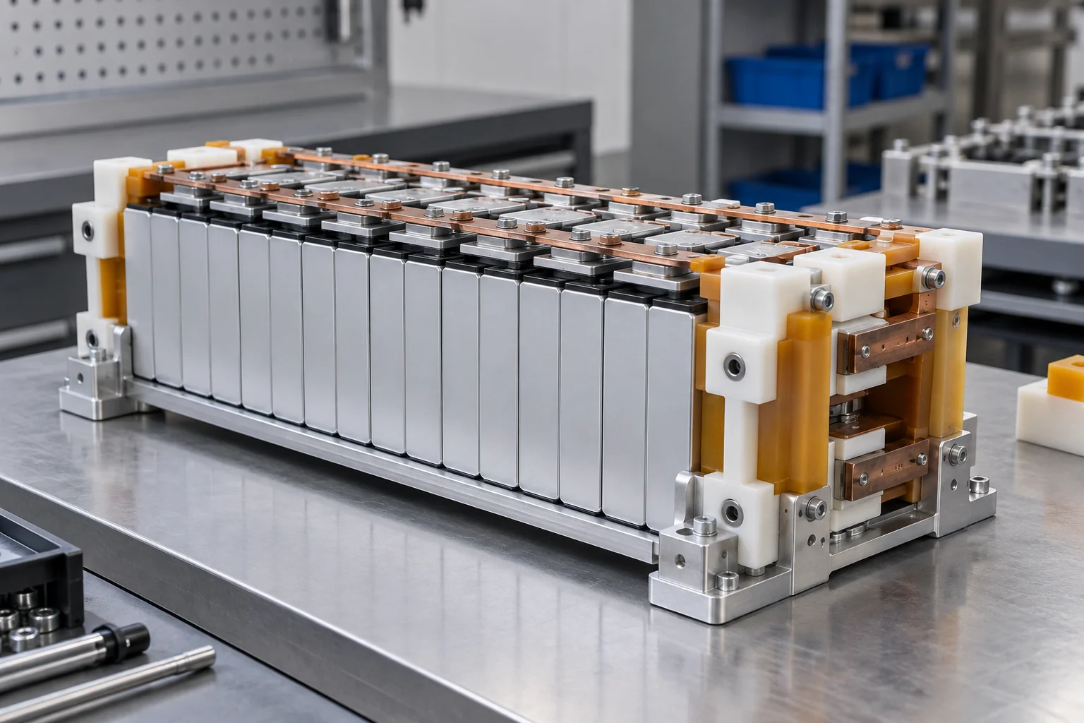
Define working voltage, required spacing, dielectric properties and the complete insulation geometry. The part’s fit and thickness must follow the released design.
Include normal, peak and changing temperatures. Local hot spots can differ from ambient conditions.
Control module and pack assembly datums, stack dimensions and interfaces across the service environment.
Specify the exact resin grade, required test evidence and applicable customer requirements. A generic polymer description does not establish a rating.
Fastener compression, retained clamp loads and creep affect support and spacing. Review bearing area, inserts and sustained stress.
Battery-system components should be selected using insulation, temperature, flame requirements, dimensional stability, load and chemical exposure together. Component machining does not establish battery certification or system-level electrical safety. Agree any required finished-part validation and evidence before order.
Sensor housings, connector bodies, PCB supports, insulators, spacers and terminal blocks connect electrical requirements to precise assembly interfaces.
Specify voltage, insulation function and grade data under relevant temperature and moisture conditions.
Include condensation, humidity and thermal cycles that can affect fit and surface electrical behavior.
Locate cavities, bores and mounting features from functional datums. Provide mating-part geometry and allowed misalignment.
Specify hardware, installed position, surrounding material and retention requirements. Clamping can distort thin housings.
Standard insulating plastics are not automatically ESD-safe or EMI-shielding materials. Supply any static-dissipative or shielding specification separately, with the required evidence. Sensor alignment and electrical separation should remain controlled through both assembly and service.
Gears, bushings, plain bearings, rollers, wear pads and guides may serve seat adjusters, HVAC actuators, door or interior mechanisms and production fixtures.
Provide steady and peak loads, torque reversals and supported contact area. Tooth or bore geometry must suit the full mechanism.
Specify motion type, speed, cycle rate and permissible lost motion. Center distance and thermal movement affect gear engagement.
Suitable polymers may reduce noise or friction, but pairing, finish and lubrication determine the actual behavior.
Shaft roughness, hardness, alignment and hot-spot temperature influence wear. Define the actual counterface.
Plastic motion components can reduce noise and friction in suitable designs. Load, speed, backlash, lubrication, temperature and mating materials still determine service life. Dry-running or long-life behavior requires the appropriate grade, geometry and validation.
Coolant manifolds, valve blocks, pump components, housings, fittings and sensor interfaces require a complete fluid and connection specification.
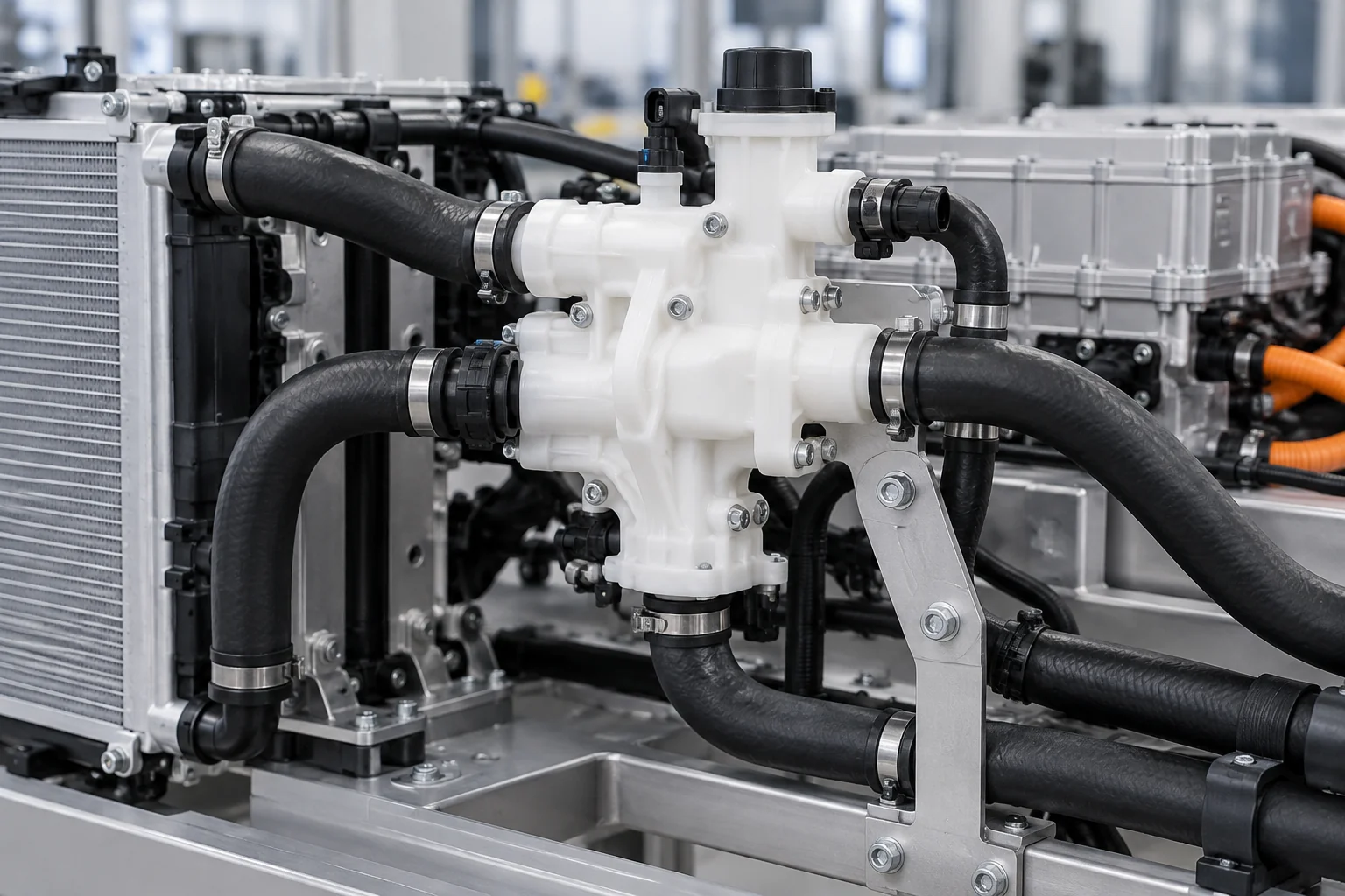
Identify the exact coolant, additives, oils or process fluids, concentration and exposure duration. Cleaning or test media may differ from service media.
Include continuous, peak, transient and cyclic conditions. Generic chemical resistance does not establish a pressure rating.
Release O-ring or gasket geometry, fitting type, port threads and installation requirements. Consider loads from connected tubing.
Different expansion between plastic, metal and seals can change retained load, alignment and leakage behavior.
Select for the actual fluid, temperature, pressure, sealing method and long-term thermal cycling. Project-specific leak, pressure or cleanliness requirements can be reviewed; dimensional inspection is separate from an agreed fluid-system validation test.
Brackets, guides, spacers, actuator parts, covers and housings can combine assembly function with lower mass and suitable contact behavior.
Compare the complete design, including support and hardware. Lower density does not guarantee a lighter or adequately stiff assembly.
Suitable contacts and guides may reduce vibration or contact noise. Review fit, wear and representative mechanism trials.
Check the grade against cleaning products, moisture and other exposure rather than assuming universal resistance.
Machined contours can combine mounting or locating features. Electrical isolation is available with suitable documented grades where needed.
Metal replacement may require changed section thickness, support and fastening. Review stiffness, creep, visible finish and assembly space before choosing the material; plastic is not automatically the better solution for every cabin or mechanism part.
Assembly nests, inspection fixtures, welding/bonding fixtures, sensor-positioning tools, poka-yoke tooling and test nests should follow the process and workpiece.
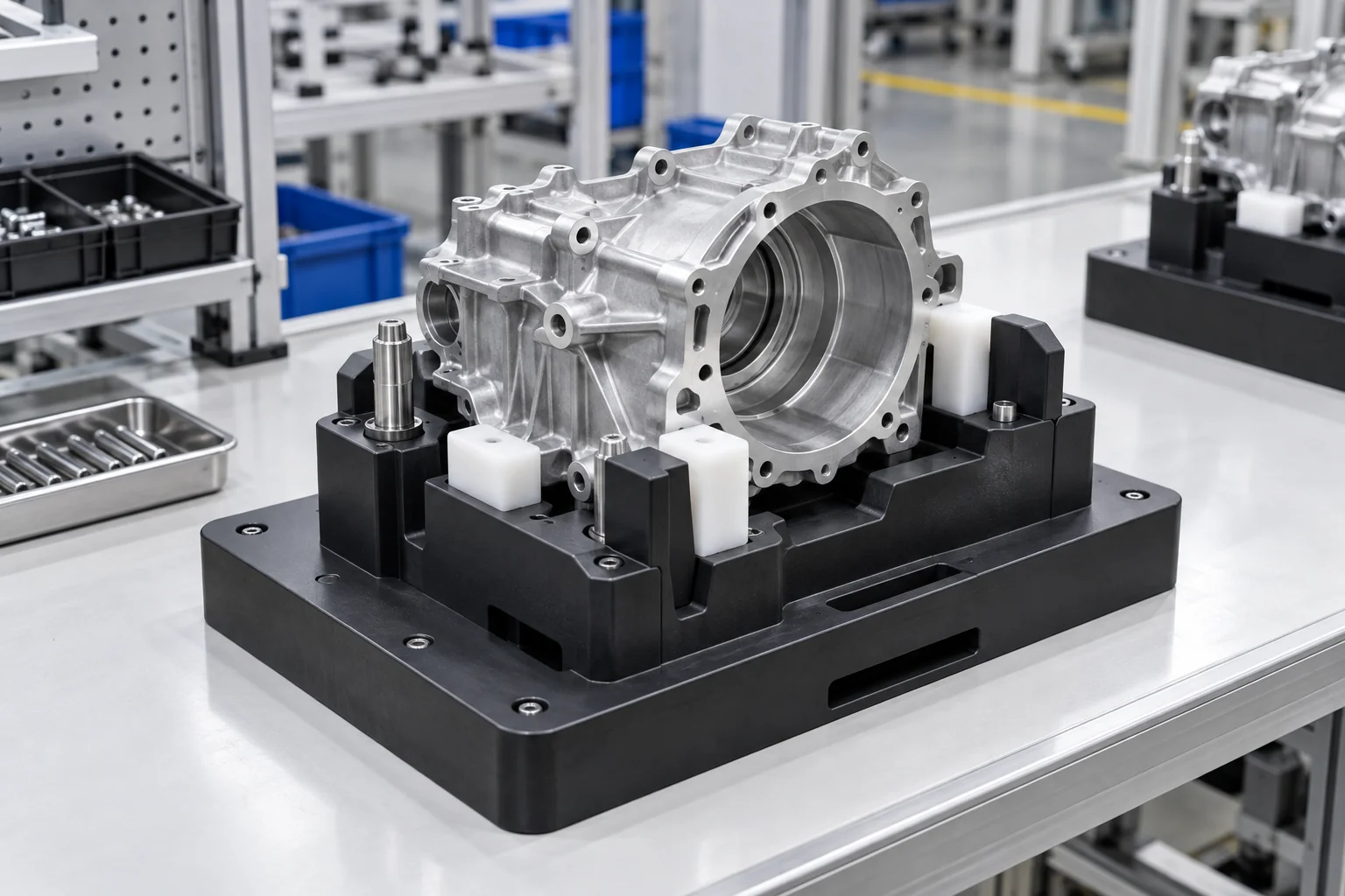
Suitable pads can protect finished parts. Control debris, contact force, edge radii and cleanliness.
Polymer tooling may ease operator handling while retaining enough section and support for repeatable positioning.
Machine drawing-based nests and changeover parts from released CAD without mold tooling.
Separate wear contacts and locating elements so they can be renewed without replacing the full fixture.
Use contoured support with relief for part variation, clamping, access and inspection. Review heat and spatter near welding operations.
For production teams and Tier suppliers, the workpiece revision, process forces and functional datums are essential inputs. Verify the fixture in the intended operation; a dimensionally correct nest alone does not demonstrate line capability or repeatability.
Evaluate the full duty environment, including temperature cycles, fluids, moisture, load and expected service life.
Underhood and EV applications may see elevated heat. Use the actual hot-spot and load conditions.
Repeated hot/cold cycles can shift dimensions, fits and retained fastener pressure. Include cycle extremes and frequency.
Check compatibility with exact media and concentration. Sustained stress and temperature may change the response.
Nylon can absorb moisture; electrical surfaces and fits also need wet-condition review. Specify conditioning where relevant.
Exterior and underbody exposure adds sunlight, weather and contamination. Review a suitable grade and the component’s function.
Material suitability cannot be inferred from room-temperature performance alone. Include vibration, mechanical load, exposure duration and intended location so the selected grade and design can be evaluated together.
Thin walls, inserts, close mating interfaces, thermal exposure and high cycle counts can occur in the same component.
Clamping and cutting forces can distort slender sections. Plan support and the free or restrained inspection state.
Interference can change bores and housings. Review installed dimensions, retained load and the surrounding section.
Plastic-to-metal fits can move across temperature. Define the relevant inspection and operating conditions.
Stock and machining stresses may release during material removal. Review geometry, sequence and stabilization needs.
Fillers can increase tool wear and change finish, dimensions and electrical behavior. Release the exact compound.
Sensor, connector and insert relationships need clear datums, access and practical tolerances.
Material-aware DFM should focus on functional fit and stable manufacture. Tightening every dimension can increase cost without improving the mechanism; identify which features control position, motion or sealing.
Assess the complete mechanism, including lubrication, vibration and contamination, alongside the material.
Contact stress depends on force, area, alignment and support. Include sustained and impact loads.
Rotation, sliding and oscillation produce different wear and heat. Include reversals and travel.
Peak and repeated torque influence gear teeth, hubs and retained interfaces.
Operating hours, dwell and start-stop frequency affect heating and accumulated wear.
Heat changes stiffness, expansion and friction. Evaluate both ambient and locally generated temperature.
Counterface roughness, hardness, coatings and geometry influence service behavior.
Lubrication, vibration and dirt can materially change the result. Define acceptable wear, clearance or backlash change and the validation cycle. No polymer family alone establishes lifetime durability or zero wear.
Focus tight tolerances on assembly-critical, motion-critical and sealing-critical features, with practical limits elsewhere.
| Feature | Why it matters |
|---|---|
| Bore diameter | Shaft and bearing fit |
| Hole position | Assembly alignment |
| Gear geometry | Motion transmission and backlash |
| Spacer thickness | Stack control |
| Housing interface | Sensor and connector fit |
| Insert location | Fastener and assembly integrity |
| Manifold port position | Fluid routing and fitting alignment |
| Flatness | Mounting stability |
| Datum relationship | Multi-part assembly |
Release GD&T, mating geometry, critical surface finish and the required inspection state. Temperature, moisture, creep and clamping can change dimensions. Agree a realistic feature-specific plan rather than a blanket capability number.
Customer-specified automotive inspection, traceability, material, electrical and documentation requirements can be reviewed during quotation.
Confirm exact resin grade and any approved additives, stock form or supplier designation.
Check drawing-defined critical interfaces, datums and reportable features.
Agree availability, sample scope, report format and approval step where requested.
Maintain released CAD, drawing changes, hardware BOM and acceptance criteria for repeat programs.
Confirm the required linkage between supplied stock, machining lot and delivery documents before order.
Review required supplier documents and their availability for the exact grade and manufacturing scope.
Program-specific PPAP, APQP, IMDS, OEM approval or certification requirements must be stated early and confirmed separately. Machining and inspection capability does not imply IATF 16949 certification, approved-supplier status or automatic program acceptance.
Use each stage to close the relevant fit, material and validation questions before recurring supply.
Validate geometry, initial fit and material direction using representative mating components.
Refine tolerances, assembly and service conditions; complete the customer’s required application tests.
Support EV development, test systems and specialized vehicle programs to released drawings.
Maintain exact grade, released drawing, CNC program, inspection criteria and required documentation.
Review temperature, thermal cycling, fluids, electrical requirements, vibration, wear, load and documentation together before production.
Review POM, Nylon, PEEK, PPS, PEI, PTFE and other specified grades against the duty.
Connect housings, insulators, gears, bushings, fixtures and manifolds to functional requirements.
Manufacture drawing-based interfaces, bores, cavities and multi-face parts.
Review heat, wear, creep, wall section and assembly interfaces before machining.
Support EV development, equipment builders and OEM suppliers with controlled releases.
Agree critical-feature checks, reporting and acceptance requirements for the defined scope.
Move from application requirements to the detailed product page for geometry, interfaces and drawing preparation.
Direct answers about materials, EV insulation, motion systems, fluids, tolerances and program documentation.
POM, Nylon, PEEK, PPS, PEI, PTFE, UHMW and PC are candidates for different functions. Choose the exact grade for environment, load, interfaces and required evidence.
POM offers useful machinability, dimensional and low-friction properties for gears, guides and bushings. Temperature, fluids, load and the mating system still need review.
Consider Nylon where toughness, impact and loaded wear favor it. Compare moisture uptake, conditioned fit and operating environment with POM.
PEEK can be a candidate for demanding thermal, chemical and mechanical duties. Confirm grade, environment, load and finished-component validation requirements.
PEEK, PEI, PPS and other insulating grades may be considered. The correct choice depends on voltage, temperature, flame requirements, mechanical load and documented grade properties.
Yes, suitable mechanisms can use polymer gears. Tooth geometry, torque, speed, backlash, lubrication, alignment and temperature control suitability.
There is no universal choice. Compare the exact grade with coolant chemistry, concentration, temperature, pressure, seal design and thermal cycling.
Prioritize bores, locating holes, gear geometry, spacer height, housing interfaces, inserts and seal-related features. Define the functional datums and inspection state.
Yes, drawing-based prototypes and low-volume components can be reviewed for development, test equipment and specialized programs. Supply quantity, grade, CAD revision and acceptance requirements.
Specify exact grade evidence, inspection reports, traceability and program-specific requirements before quotation. Availability and acceptance scope must be confirmed rather than inferred from general machining capability.
VEHICLE SYSTEM. DUTY ENVIRONMENT. EXACT GRADE.
Upload your automotive component drawing or CAD model and specify the exact material grade, quantity, vehicle system, operating temperature, mechanical load, electrical requirements, fluid exposure, critical tolerances and documentation needs. TOPS Plastics can review the geometry and machining feasibility before quotation.
Company, name, email and phone are required. Country, part number, quantity and drawing upload are optional. Include technical requirements in the drawing or email; combine CAD and supporting files into one ZIP if useful.
info@tops-precision.comSTEP / STP / IGES / X_T / DWG / DXF / PDF or ZIP, maximum 10 MB. Larger packages can be shared by email. Agree confidential-file handling before sending sensitive drawings.