01
Plastic Assembly Fixtures
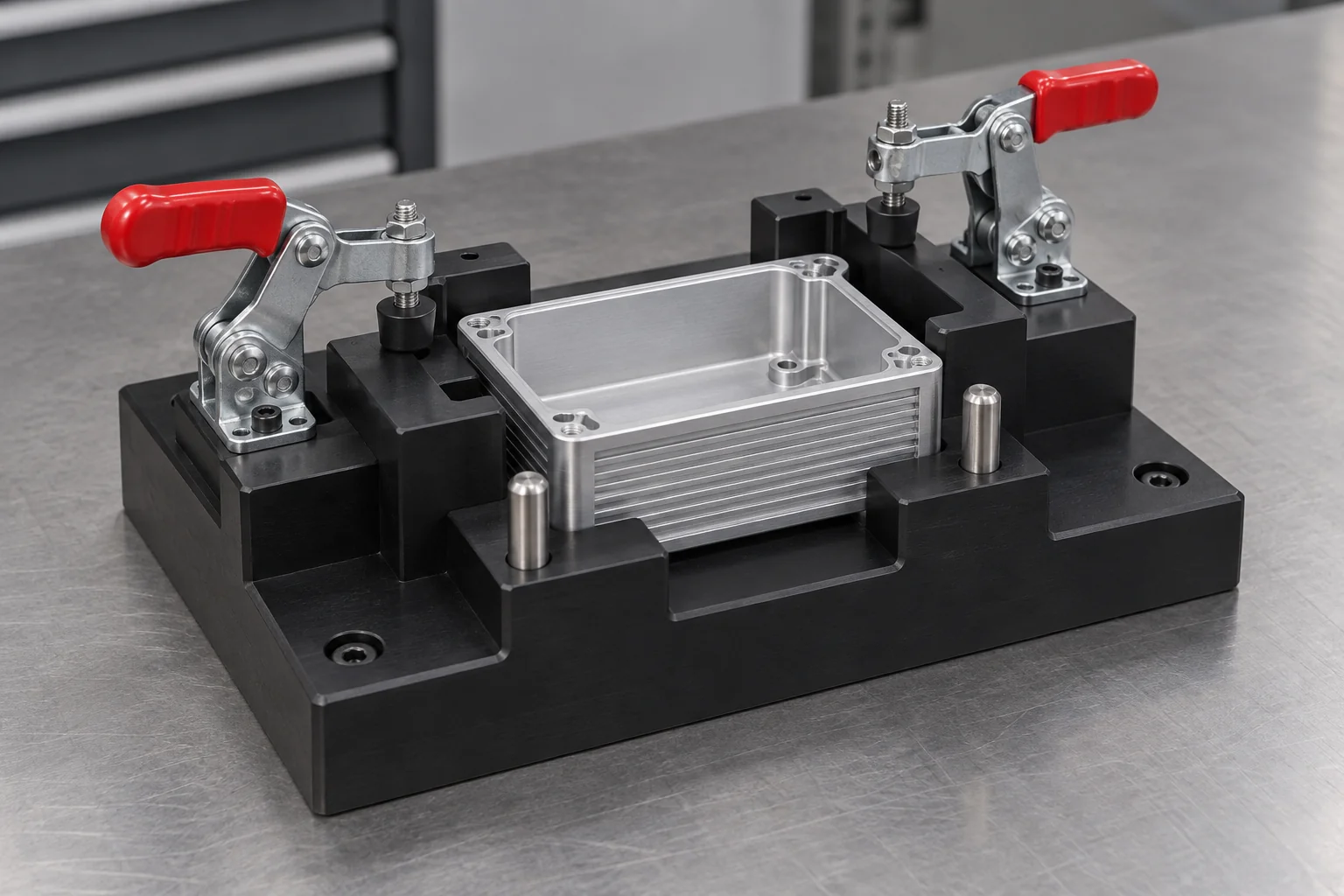
Hold components in the correct relationship during fastening, bonding, wiring, insertion and assembly. Provide access for tools and a clear loading sequence.
Discuss this fixture →
LOCATE. HOLD. REPEAT.
TOPS Plastics manufactures custom plastic jigs and fixtures for workholding, assembly, inspection, drilling, testing and production support. We CNC machine fixture plates, nests, locator blocks, inspection fixtures and custom tooling from POM, Nylon, PEEK, UHMW, PEI and other engineering plastics according to customer CAD files and process requirements.
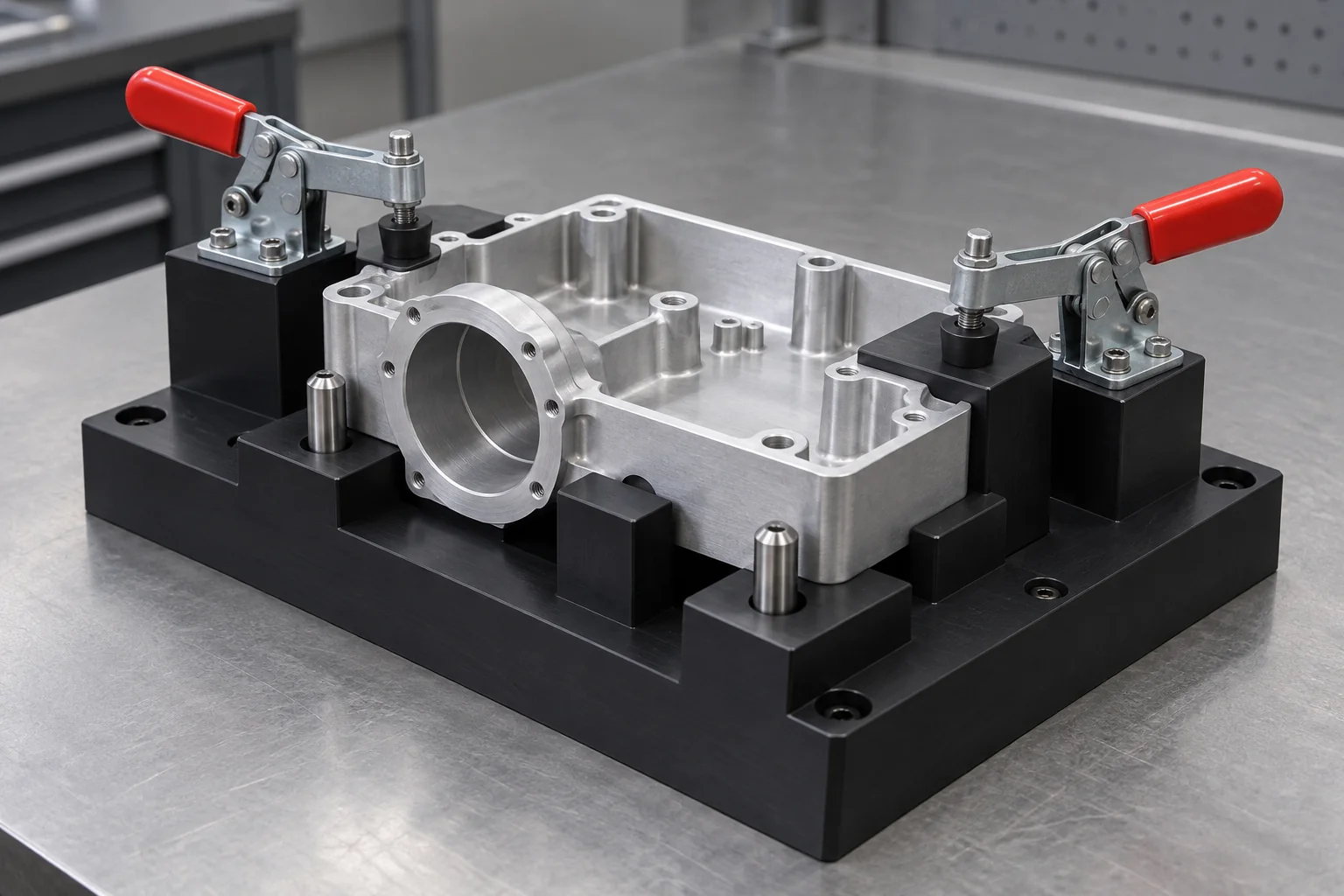
Build-to-print production tooling starts with the workpiece, operation and required locating relationships.
| Capability | TOPS Plastics |
|---|---|
| Fixture types | Assembly, inspection, drilling, workholding, test and nest fixtures |
| Materials | POM, Nylon, UHMW, PEEK, PEI, PPS and specified grades |
| Features | Pockets, nests, holes, locators, stops, slots and inserts |
| Hardware | Pins, bushings, clamps, inserts and fasteners where specified |
| Processes | CNC milling, turning, drilling, tapping and 5-axis machining |
| Production | One-off tooling, duplicate fixtures and repeat tooling |
| Input | CAD models, part drawings, process requirements and samples |
| Inspection | Critical datum, hole, locator and interface inspection |
Eight tooling functions, each built around the part, process and loading sequence. Specify the locating references and required hardware.
Hold components in the correct relationship during fastening, bonding, wiring, insertion and assembly. Provide access for tools and a clear loading sequence.
Discuss this fixture →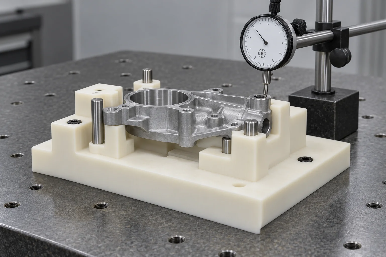
Position parts consistently for dimensional or visual inspection. Define the datum system, gauge interfaces and acceptance method.
Discuss this fixture →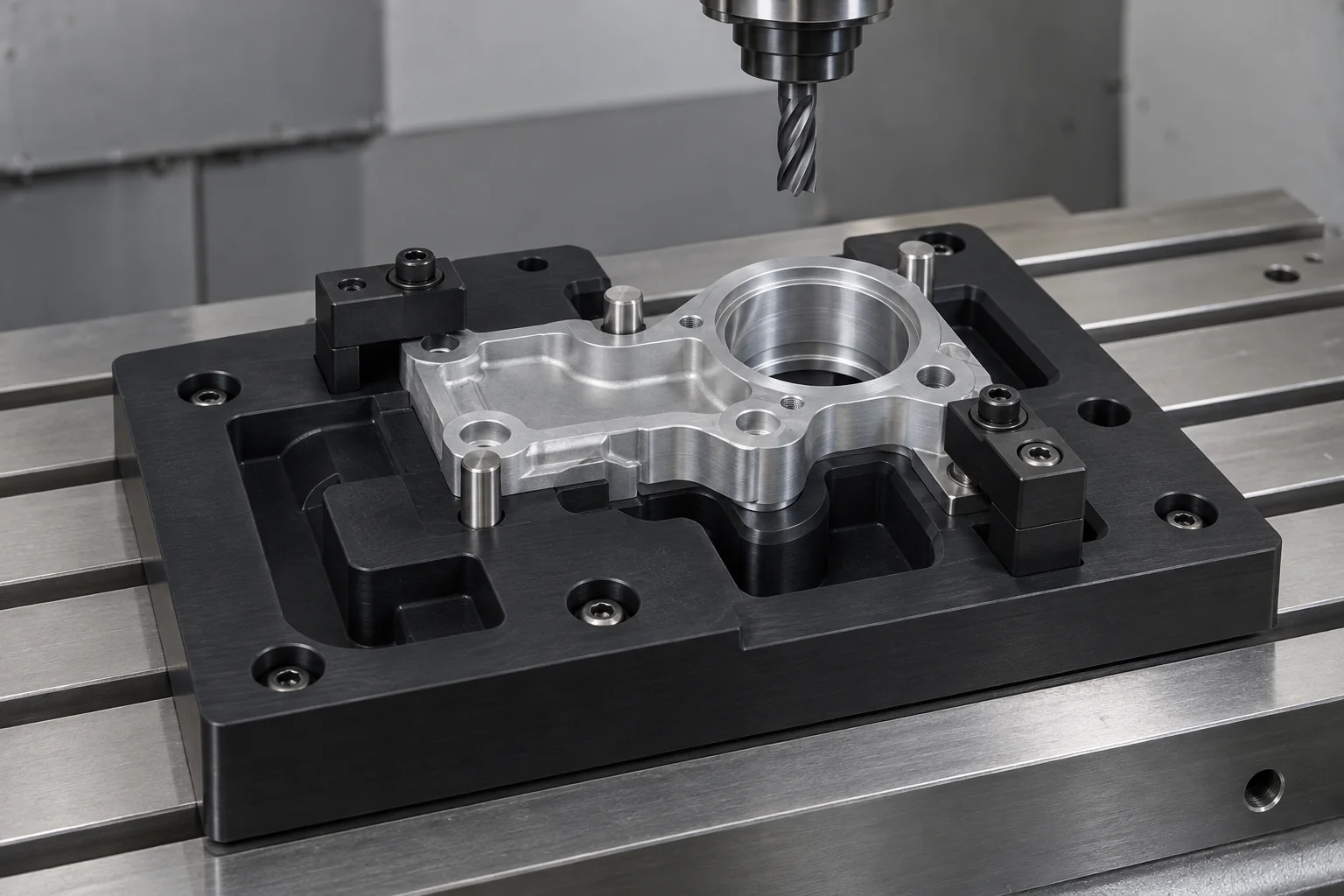
Locate and support parts for machining, secondary operations or process positioning. Review cutting forces, support and clamp retention.
Discuss this fixture →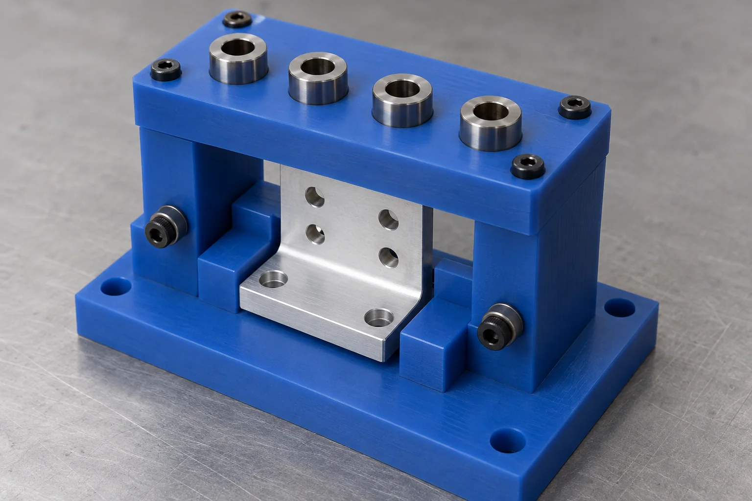
Locate repeated hole-making operations using specified drill bushings. Define bushing size, retention, drill access and chip clearance.
Discuss this fixture →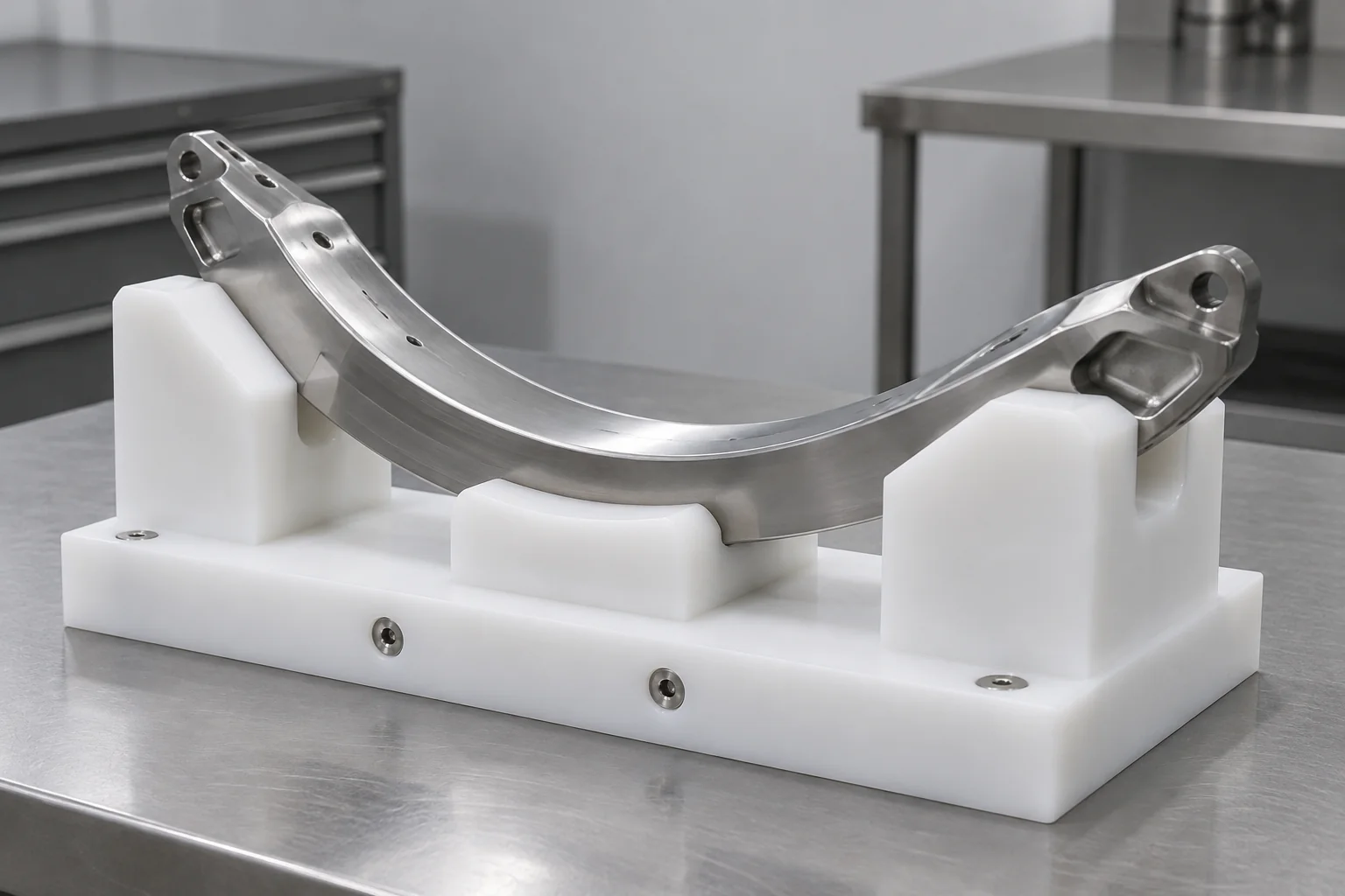
Use custom cavities or profiles to support a specific part without forcing it into a distorted shape. Relieve nonfunctional surfaces.
Discuss this fixture →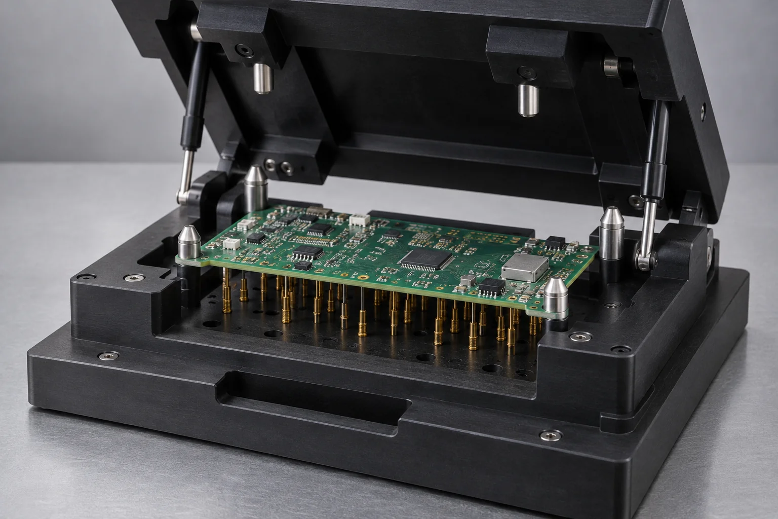
Hold electronics, sensors and connectors for functional testing. Specify probe access, connector alignment and electrical requirements.
Discuss this fixture →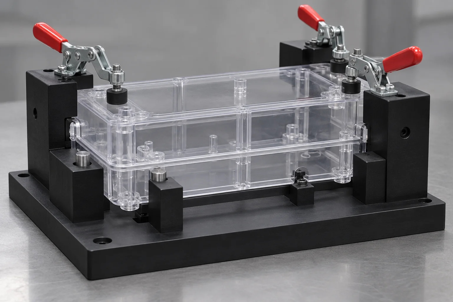
Maintain alignment during adhesive bonding, ultrasonic welding, heat staking or other joining operations. Review heat, chemical exposure and process forces.
Discuss this fixture →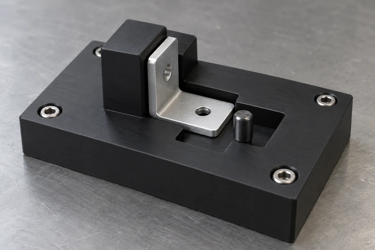
Use keyed nests, asymmetric stops or orientation features to reduce incorrect part loading. Validate the intended error-proofing with representative parts.
Discuss this fixture →Plastic jigs and fixtures are custom manufacturing tools used to locate, support, hold, guide, inspect or assemble parts consistently during production.
A jig usually guides or controls an operation, such as locating a drill through a bushing.
A fixture primarily positions and holds the workpiece. Many custom production tools combine both functions.
Engineering plastics are useful where tooling contacts finished surfaces, reduces handling weight, electrically isolates components, resists corrosion or reproduces complex part contours.
Selected polymers can help protect cosmetic and finished surfaces. Contact pressure and cleanliness still require control.
Lower-density materials can make equivalent-size tooling easier to move and load; compare the complete assembly.
Selected grades suit wet or chemical environments after exposure and temperature review.
Insulating grades can provide electrical separation in selected electronics and test applications.
Suitable materials can ease sliding or loading at nests and contact interfaces.
Machine complex contours and part nests directly from released CAD.
POM is often a starting point for precision locators, UHMW for sliding contact, Nylon for tough tooling, and PEEK or PEI for demanding thermal or electrical conditions. Verify the actual grade and operating environment.
| Material | Best for | Main strength | Main consideration |
|---|---|---|---|
| POM / Delrin | Precision nests and locators | Low moisture uptake and dimensional stability | Moderate temperature; grade-dependent exposure |
| Nylon | Tough production fixtures | Impact resistance | Moisture absorption and conditioning |
| UHMW | Sliding / protective contact | Low friction and wear resistance | Lower stiffness and creep under sustained load |
| PEEK | Demanding / high-temperature fixtures | Mechanical and thermal performance | Higher material cost |
| PEI / Ultem | Electrical / thermal tooling | Heat and electrical performance | Higher cost; chemical compatibility |
| PPS | Chemical / stable tooling | Heat and chemical resistance | Brittleness and notch sensitivity |
| HDPE | General handling fixtures | Chemical resistance and cost | Lower rigidity and dimensional stability |
Locate from defined functional datums rather than matching every external surface. A relieved nest reduces over-constraint and allows repeatable seating.
LOCATE FIRST. CLAMP SECOND.
A conceptual plan view: the three primary supports sit beneath the workpiece. Side contacts and an end stop establish the remaining locating references.
Separate locating from retention. Place clamp reactions near supports and verify the actual workpiece geometry.
Establish the main seating plane with three suitably separated support contacts in a typical prismatic setup.
Two contacts on a second face establish lateral alignment and control rotation about the primary-plane normal.
One end stop completes the locating reference for a typical 3-2-1 arrangement.
Specify pin position, fit and access. A round-and-relieved locator pair may avoid binding where two holes locate a part.
Support functional areas while providing relief for part variation, radii and debris. Do not use clamps to force a poor fit.
The 3-2-1 principle is a practical starting concept for suitable prismatic parts, not a universal prescription. Cylindrical, flexible or irregular workpieces require a locating strategy suited to their geometry. Clamps maintain seating against the locators.
Use enough retention for the operation while limiting deflection, surface damage and long-term polymer compression.
Direct load into supported areas so the workpiece and fixture do not bend unnecessarily.
Thin or delicate parts need controlled force and adequate contact area. Review creep under sustained loading.
Provide clear access, seating visibility and safe clearance for hands and tools.
Match clamp actuation and release to production volume and operator sequence.
Possible methods include toggle, screw, spring and pneumatic clamps, or passive retention where suitable. Magnetic retention requires a compatible workpiece and system; it does not act directly on an ordinary plastic fixture body. Validate retention for actual process loads.
Place contacts around cosmetic and functional surfaces. A softer or low-friction polymer may reduce scratching, but trapped debris, pressure and cleaning remain important.
Use clean contact pads and avoid small high-pressure contacts on visible faces.
Keep burrs, chips and exposed hardware away from coated surfaces.
Review coating cure, contact load and cleaning chemicals.
Provide broad support and release clearance without dragging the part.
Define permitted contact zones and surface acceptance criteria.
Protect cosmetic faces while preserving connector and assembly access.
Fixture accuracy depends on more than machining tolerance. Material stability, locator wear, clamp force, datum design and the environment affect production repeatability.
| Factor | Why it matters |
|---|---|
| Material stability | Temperature and moisture can change dimensions; select and condition the grade appropriately. |
| Datum design | Establishes repeatable seating and orientation. |
| Locator wear | Wear changes part position over repeated cycles. |
| Clamp force | Can distort the part or compress the fixture. |
| Base flatness | Controls seating on the bench or machine interface. |
| Insert / pin fit | Affects locator position, retention and service replacement. |
| Environmental temperature | Inspection and service temperatures affect polymer dimensions. |
| Cleaning / contamination | Debris can prevent full seating. |
Specify the measurement state, functional datums and repeatability trial rather than assuming a dimensional inspection alone proves performance.
Electrical insulation, charge dissipation and chemical compatibility are different requirements. Specify each independently.
Define voltage, required isolation and test conditions for the complete tooling assembly, including metal hardware.
Specify a documented grade, electrical resistance range, test method and grounding arrangement where needed. Standard insulating plastic is not automatically ESD-safe.
Review cleaners, flux, oils, coolants, solvents and process chemicals with concentration, temperature and exposure duration.
Black color does not establish conductivity or static-dissipative behavior. Documented grade properties and assembly validation are needed before making an ESD performance claim.
The entire fixture need not be sacrificial. Replaceable high-wear features can reduce maintenance scope.
Use specified bushings for repeated drill guidance, with agreed fit and retention.
Use wear-resistant locating points where cycle count justifies them.
Renew worn contact faces without replacing the complete base.
Protect repeated screw interfaces; review insert retention in the selected polymer.
Replace a localized worn contour while preserving the base and datum system.
Accommodate approved variants or compensation, with a secure locking method.
Datum relationships and locator positions usually matter more than tight tolerances on every external surface. Agree feature-specific values after drawing and material review.
| Feature | Why it matters |
|---|---|
| Locator pin position | Controls part positioning and repeatability |
| Nest geometry | Controls part seating without interference |
| Datum surface flatness | Provides a stable reference plane |
| Hole pattern | Aligns hardware and workpiece interfaces |
| Clamp location | Controls force distribution |
| Gauge feature | Affects inspection result and measurement uncertainty |
| Insert position | Supports repeatable wear-feature replacement |
| Base dimensions | Integrates with the machine or bench |
No universal tolerance applies to every fixture. Material, size, support, temperature, measurement method and service loads determine what is appropriate.
Define the operation and acceptance criteria before releasing tooling geometry.
Specify assembly, inspection, drilling, testing or machining, together with process forces and tool access.
Where practical, reference the surfaces that matter on the finished part and define the fixture-to-machine interface.
Provide only the locating contacts needed; allow for part tolerance and thermal movement.
Use keyed features, visible seating and a simple clamp sequence to reduce loading mistakes.
Keep clamps and locators away from critical appearance areas where possible.
Provide chip and debris relief with accessible cleaning surfaces.
Separate high-cycle contact elements from the durable fixture base.
Review conditioning and dimensional changes, particularly for Nylon and larger fixtures.
Manufacturing follows the released CAD, datum scheme, material specification and hardware requirements.
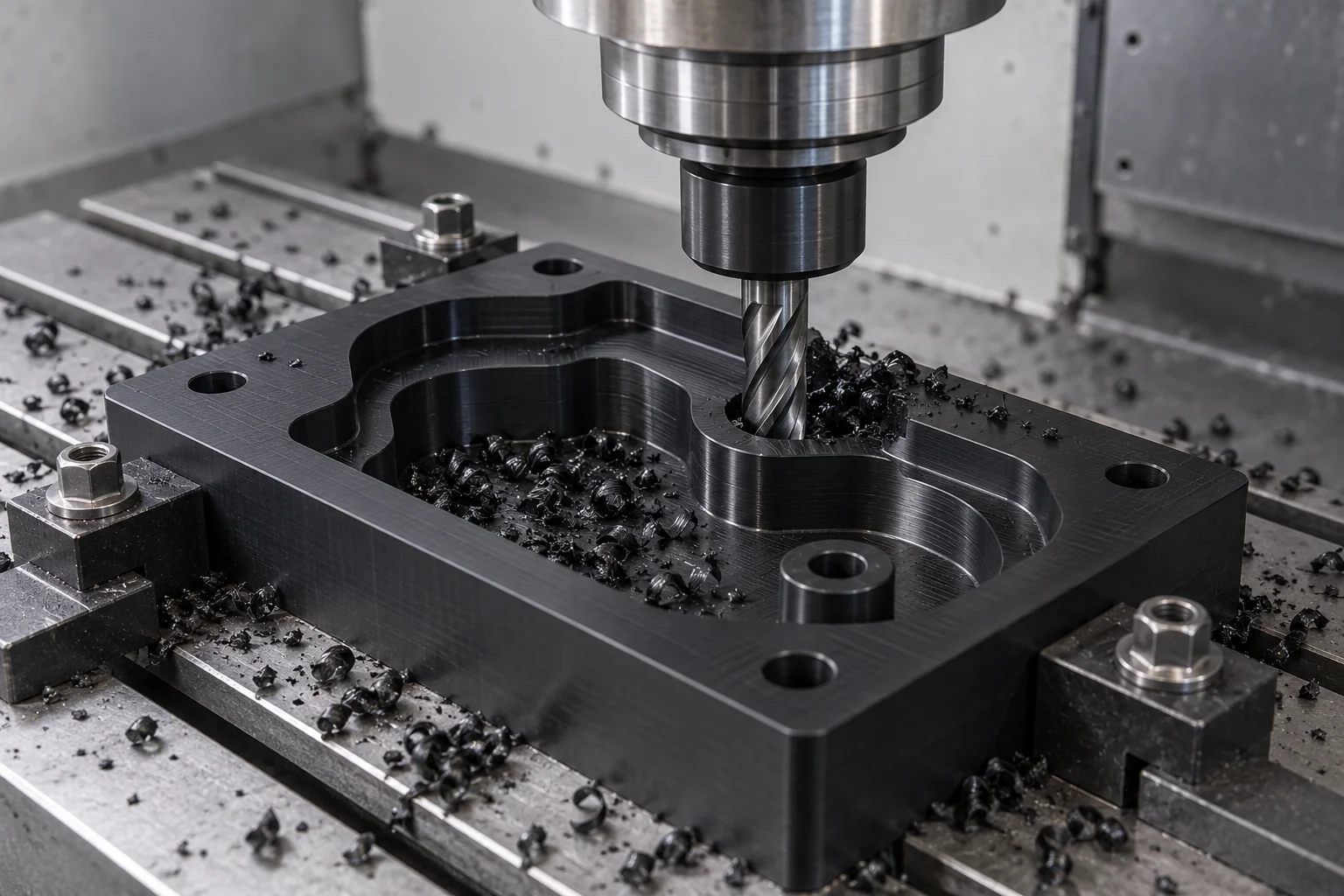
Machine fixture plates, nests, pockets, locating surfaces and clamp features.
Produce complex part-contour nests and multi-face features where geometry and access justify the process.
Produce cylindrical locators, sleeves and other rotational fixture components.
Create specified interfaces for clamps, pins, screws and hardware.
Install bushings, locator pins, threaded inserts and clamps to the agreed assembly specification.
Verify datums, hole positions, seating, hardware and the fixture assembly; use a customer mating part where supplied.
Choose plastic where protective contact, electrical isolation, handling weight or chemical compatibility matter. Aluminum may suit higher stiffness or clamping loads; hybrid tooling can combine a metal base with polymer contacts.
| Factor | Plastic fixture | Aluminum fixture |
|---|---|---|
| Weight | Usually lower for equivalent geometry | Usually higher for equivalent geometry |
| Non-marring contact | Good potential with suitable contacts and cleaning | May need protective pads |
| Electrical insulation | Available with insulating grades | Conductive unless an isolation system is provided |
| Stiffness | Lower; support and section matter | Generally higher |
| High temperature | Grade and load dependent | Often suits higher temperatures; alloy and condition matter |
| Complex machining | Complex nests and contours possible | Complex geometry possible |
| Chemical resistance | Polymer and exposure dependent | Alloy, coating and exposure dependent |
| Operator handling | Can reduce lifting mass | May require handling assistance |
| High clamping load | Compression and creep require review | Often better suited; design still controls performance |
These are tooling applications to review against the actual process, rather than blanket qualification claims.
PCB nests, connector fixtures and test tooling with specified electrical requirements.
Assembly, checking and positioning fixtures for production workstations.
Precision assembly and inspection tooling using materials suitable for the specified process.
PEEK, PEI and technical tooling with defined cleanliness and environmental requirements.
Lightweight assembly and inspection tools built to customer drawings.
Workholding and drill fixtures with operation-specific force and access review.
Product positioning and repetitive assembly tooling integrated with station interfaces.
Agree the inspection plan before production. A customer mating part or master sample supports an additional fit check.
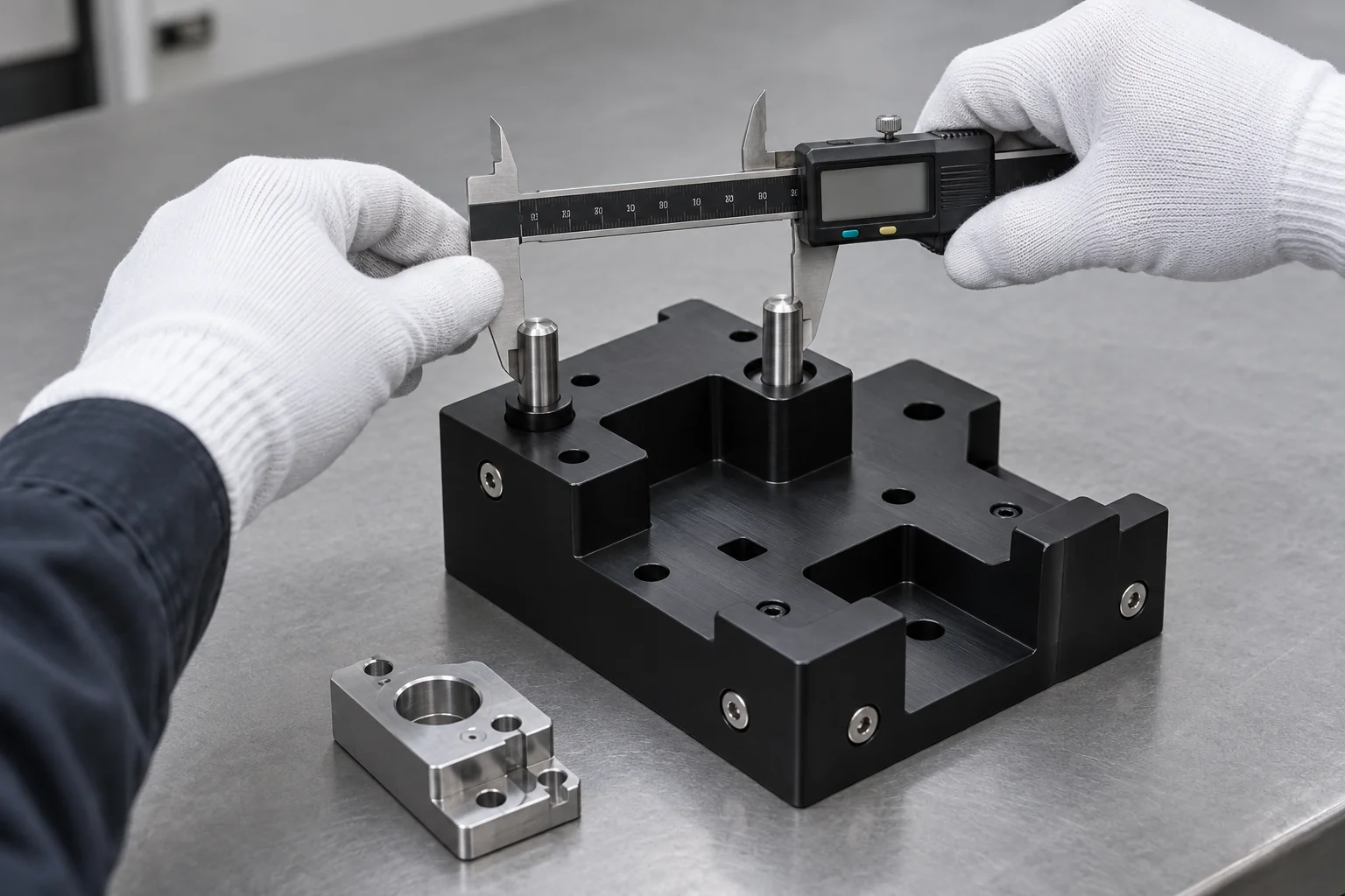
Check the specified grade and requested traceability documentation.
Confirm revisions, critical features and measurement references.
Measure seating faces and the fixture mounting interface.
Inspect pin and stop locations relative to agreed datums.
Check functional contours, clearances and support relationships.
Review installed positions, fit and retention requirements.
Check components, travel, clearance and supported contact points.
Where a mating component is supplied, check seating and loading; agree repeated-load trials if required.
Protect locating faces, hardware and critical surfaces for shipment.
A fit check is distinct from a validated production process. Functional tests, gauge studies and capability acceptance require agreed methods, samples and operating conditions.
Tooling progresses through an agreed release process, with lessons from loading and wear trials captured in the next revision.
Validate the locating concept, mating-part fit and operator loading.
Evaluate cycle time, repeatability and wear in the intended process.
Use released CAD, standardized hardware and agreed inspection criteria.
Supply matching tooling for multiple lines or workstations with controlled revisions and datum interfaces.
A good fixture must locate repeatably, protect critical surfaces, control clamp force, accommodate production wear and simplify operator loading.
Manufacture around the released workpiece and process requirements.
Select the machining route for the nest and multi-face geometry.
Review material choices against temperature, moisture, contact and chemical exposure.
Focus inspection on functional datum and locator relationships.
Review contact zones and suitable polymer interfaces.
Include specified inserts, pins, bushings and clamp components.
Support prototypes, repeat tooling and controlled duplicate sets.
Agree critical measurements and mating-part checks before manufacture.
Answers about datum strategy, protective contact, ESD grades, hardware and fixture validation.
They locate, support, hold, guide, inspect or assemble parts during production. Common uses include assembly nests, drill jigs, inspection fixtures and test tooling.
A jig usually guides an operation; a fixture primarily holds and locates the part. Some custom tools perform both functions.
POM is often a useful starting material for precision nests and locators. Final selection depends on load, temperature, moisture, chemicals and the required datum stability.
Yes, suitable Delrin / POM grades can be used for machined assembly nests and locating blocks. Review contact pressure, temperature, exposure and the actual grade.
UHMW is useful for sliding and protective contact where low friction matters. Its lower stiffness and creep must be considered for precision locators or sustained clamp loads.
Yes, specified metal pins, bushings and threaded inserts can be integrated into a plastic body. Their fit, retention, spacing and replacement method require definition.
Only when the specified material and complete fixture meet the required electrical criteria. Ordinary insulating plastic is not automatically static-dissipative or ESD-safe.
Accuracy is feature- and application-specific. Agree tolerances, material conditioning, temperature, datum inspection and repeatability testing after reviewing the drawing.
A sample can support measurement and replacement review. Supply mating-part data, functional datums and acceptance criteria; wear or undocumented modifications must be resolved before releasing a drawing.
Choose plastic where protective contact, lower handling weight, electrical isolation or suitable chemical resistance are priorities. Aluminum or hybrid tooling may better suit high stiffness, heat or clamp loads.
YOUR PART. YOUR PROCESS. YOUR FIXTURE.
Upload your fixture CAD model, drawing, mating-part file or process description. Provide the material, fixture function, critical datums, locator positions, clamp requirements, expected cycle volume and production environment. TOPS Plastics can review the tooling geometry and machining approach before quotation.
Keep the form simple: company, name, email and phone are required. Country, part number, quantity and a drawing / CAD upload are optional. Put technical details in your drawing or email; combine 2D, 3D and mating-part files into one ZIP if useful.
info@tops-precision.comSTEP / STP / IGES / X_T / DWG / DXF / PDF or ZIP, maximum 10 MB. Larger packages can be shared by email. Agree confidential-file handling before sending sensitive drawings.