01
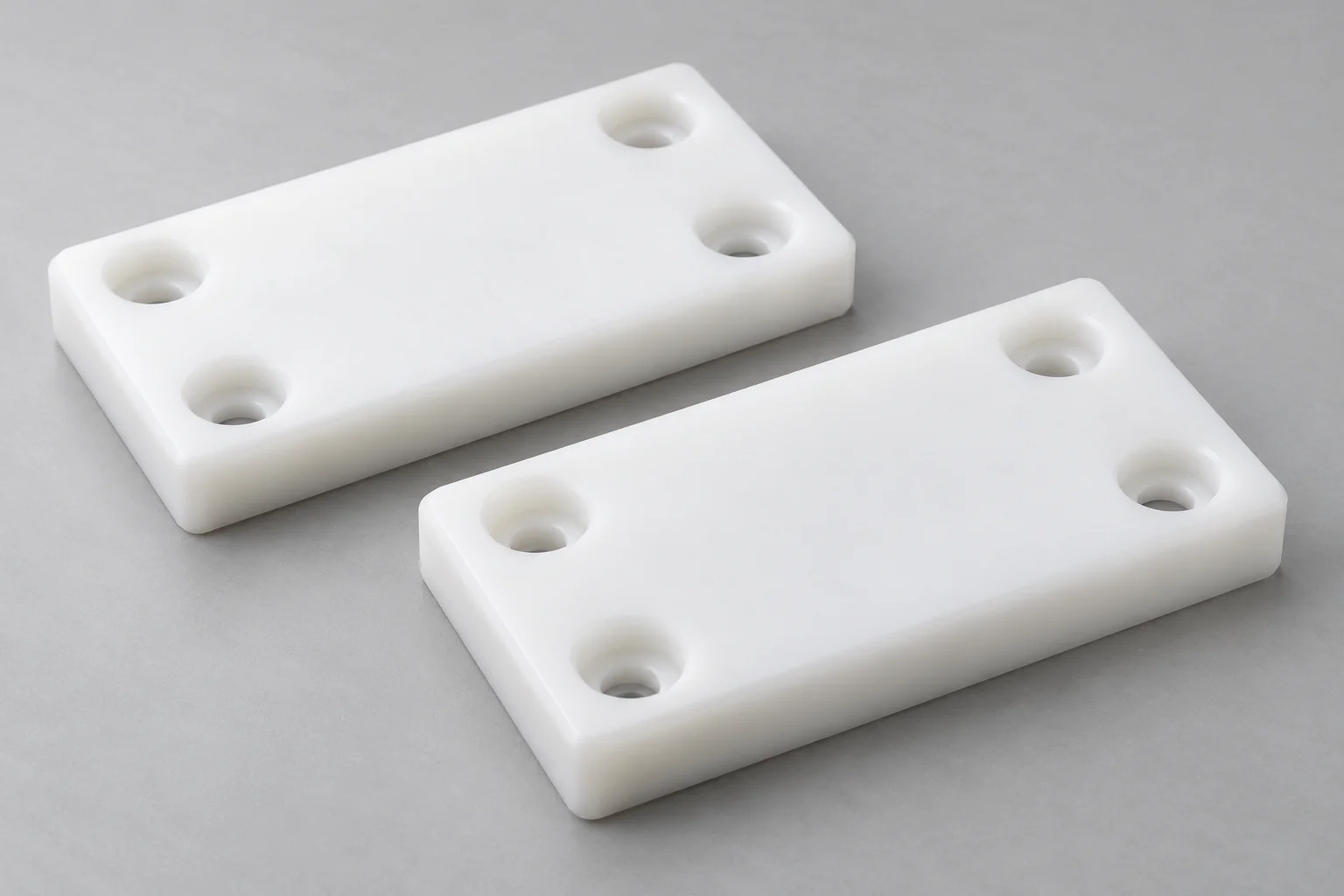
Flat Plastic Wear Pads
Rectangular or shaped sacrificial pads between sliding machine surfaces. Custom thickness and mounting recesses.
Discuss this wear pad →
REPLACE THE PAD. PROTECT THE MACHINE.
TOPS Plastics manufactures custom plastic wear pads, slide blocks, guide pads and wear plates for industrial machinery, conveyors, automation systems, agricultural equipment and material-handling applications. We CNC machine UHMW-PE, Nylon, POM and other engineering plastics with custom hole patterns, counterbores, grooves, mounting features and wear allowances according to customer drawings or samples.
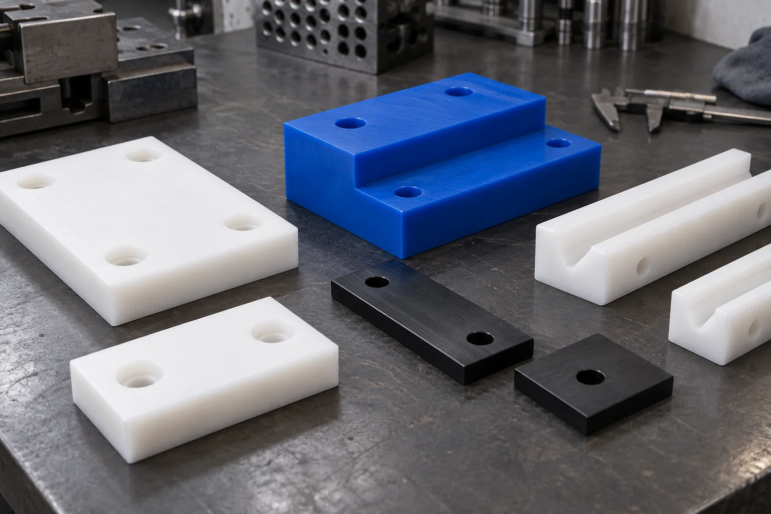
Specify the wear face, mounting pattern and working conditions. We review geometry, material and inspection requirements before quotation.
| Feature | Project requirement |
|---|---|
| Wear components | Pads, slide blocks, wear strips, guide blocks and liners |
| Materials | UHMW-PE, cast Nylon, MoS₂ Nylon, POM and specified engineering grades |
| Geometry | Flat, stepped, V-shaped, grooved, curved and custom profiles |
| Mounting | Through holes, slots, counterbores and countersinks |
| Processes | CNC milling, routing, drilling and turning where required |
| Production | One-off replacement, low-volume orders and repeat production |
| Input | Drawing, CAD, dimensioned sketch, worn sample or reference photos |
| Inspection | Length, width, thickness, hole pattern, recess depth and profile |
From flat sacrificial pads to shaped guide blocks: choose the contact geometry, then define the material, mounting pattern and replacement allowance.
Rectangular or shaped sacrificial pads between sliding machine surfaces. Custom thickness and mounting recesses.
Discuss this wear pad →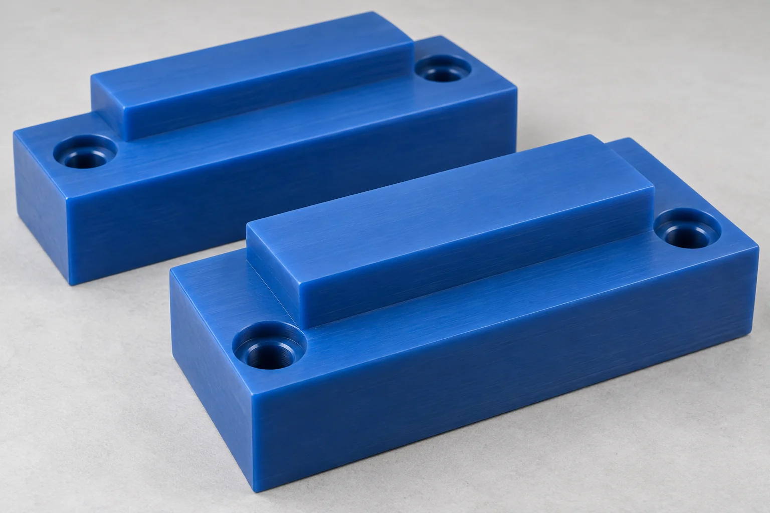
Thicker components for guided linear motion or loaded sliding interfaces. Review support and clearance.
Discuss this wear pad →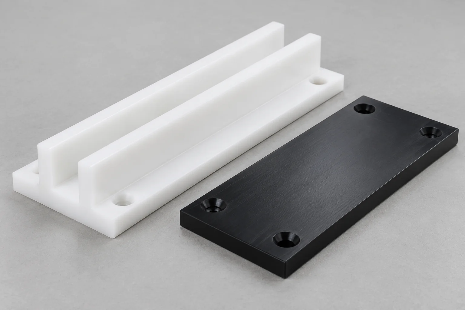
Guide moving assemblies while separating the contacting metal surfaces.
Discuss this wear pad →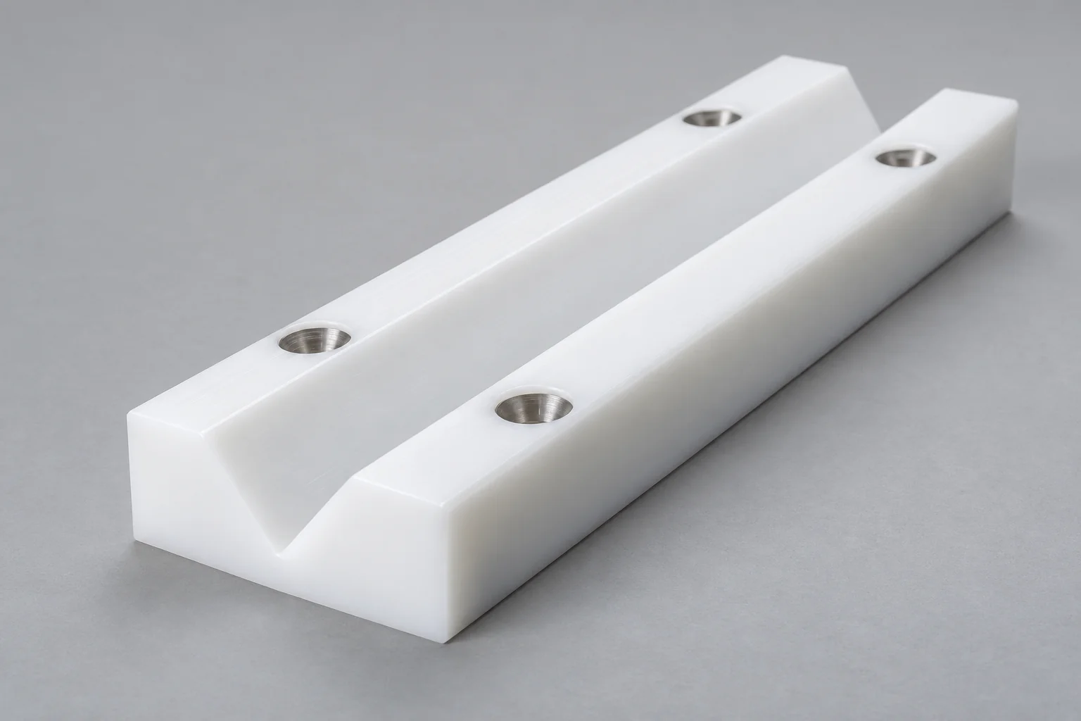
Custom angled profiles for rails, guides and matching contact surfaces.
Discuss this wear pad →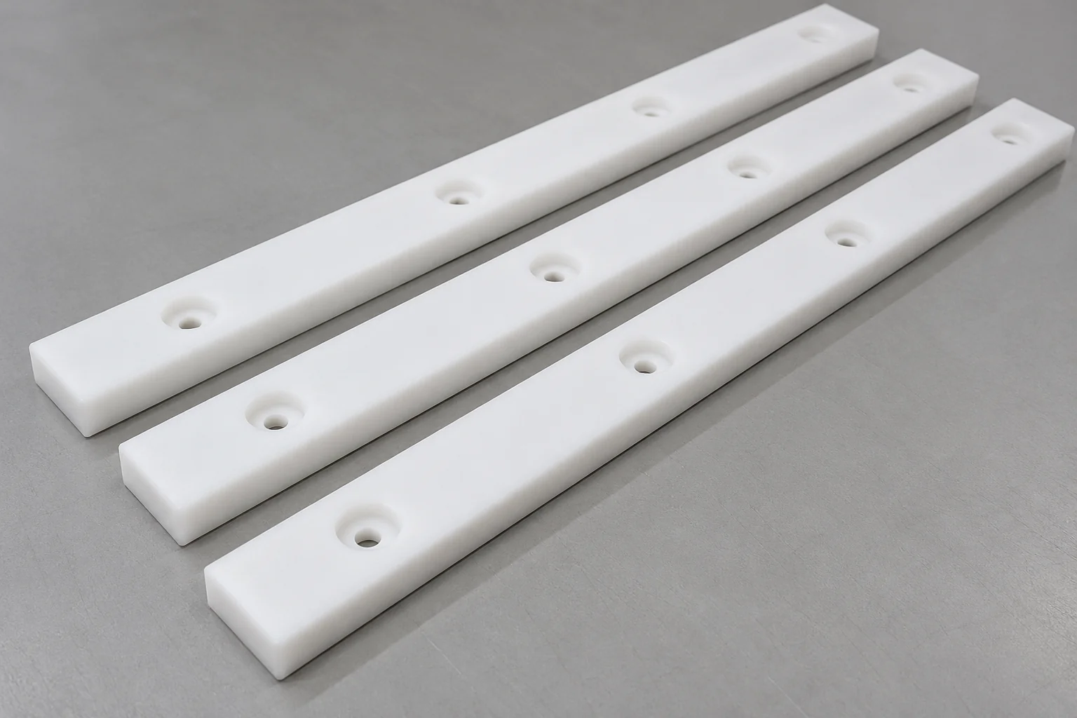
Long narrow strips for conveyors, chains, guide rails and slide tracks.
Discuss this wear pad →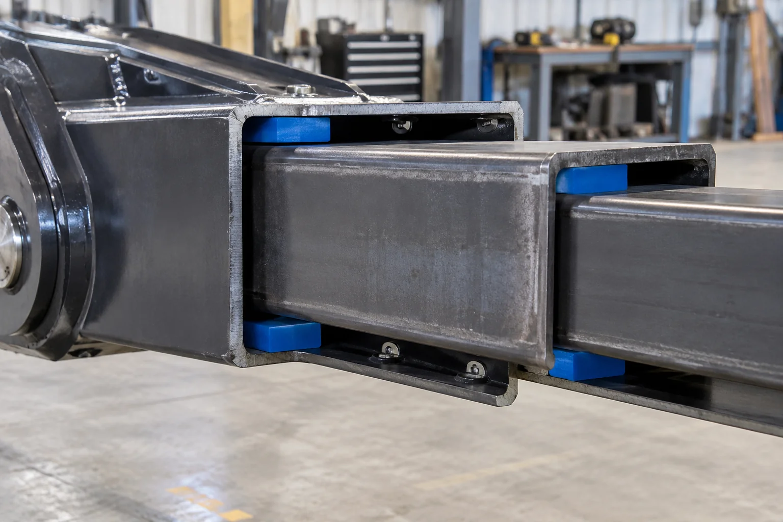
Sliding pads for extendable booms, lifting equipment and nested telescopic sections.
Discuss this wear pad →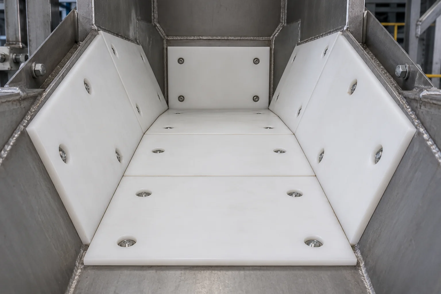
Replaceable liner pads for material handling and abrasion zones.
Discuss this wear pad →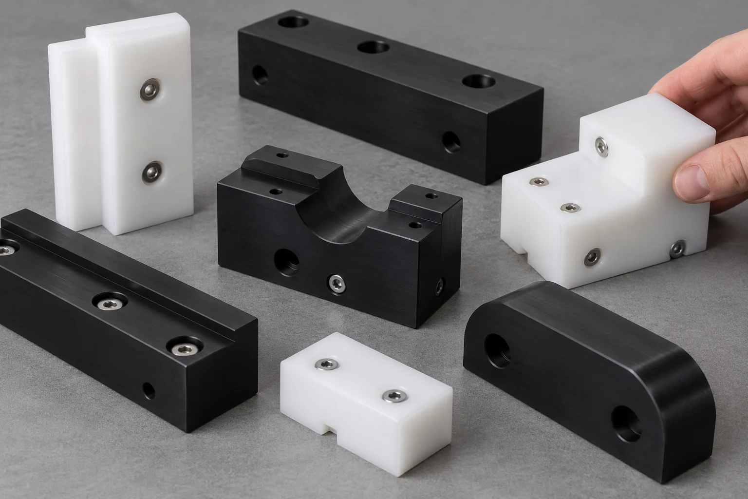
Machined stepped faces, pockets, recesses, curves and special mounting features.
Discuss this wear pad →Plastic wear pads are replaceable polymer components installed between moving or contacting machine surfaces to reduce friction, prevent metal-to-metal contact and protect more expensive structural parts from wear.
In many designs the pad is intentionally sacrificial: replacing a polymer pad is more practical than repairing a steel rail, boom, frame or machine surface. The pad, counterface and retention method must be designed together.
Wear pads provide a sliding wear surface. Plastic rollers rotate to support or guide motion; plastic bushings guide a shaft or form a sliding bearing. UHMW machining describes material and process expertise rather than a specific component.
A suitable polymer can protect the mating structure and make maintenance easier. Benefits depend on grade, load, speed, counterface and environment.
Separate rails, booms, frames and machinery with a replaceable contact surface.
Suitable grades support smoother sliding. Review dry or lubricated operation and the actual counterface.
Replace a documented pad before wear reaches the supporting structure or exposes hardware.
Consider compatible polymers for wet or chemically exposed service; verify the exact medium and temperature.
Polymer contact can reduce chatter and sliding noise in suitable equipment.
Lower material density can simplify handling compared with a comparable metal wear plate.
UHMW is usually the first material to evaluate for general sliding wear pads; Nylon for higher-load service, POM for dimensional control and PEEK for more demanding temperature or chemical conditions.
| Material | Application to evaluate | Main strength | Main consideration |
|---|---|---|---|
| UHMW-PE | General sliding and abrasion | Abrasion resistance, low friction and impact toughness | Lower stiffness; creep and thermal movement |
| Cast Nylon | Higher-load pads | Strength, stiffness and wear performance | Moisture absorption and conditioning |
| MoS₂ Nylon | Loaded sliding surfaces | Grade-specific wear and friction behavior | Moisture, counterface and exact formulation |
| POM / Delrin | Thin precision pads | Dimensional stability and machinability | Assess impact duty and operating limits |
| PEEK | High-temperature technical pads | Heat and chemical resistance in suitable grades | Higher cost; choose a relevant bearing/wear grade |
| HDPE | General lower-cost pads | Chemical resistance and economical fabrication | Usually less suitable than UHMW for demanding abrasion |
Material names alone do not predict service life. Review supplier data for the exact grade, pressure, sliding speed, temperature, moisture, chemicals and lubrication regime. A self-lubricating grade does not automatically remove the equipment lubrication requirement.
Wear pad thickness should include the material needed to support the load and the sacrificial material that may wear away before replacement.
New wear face → replacement limit → retained support
Screw-head clearance must remain at the replacement limit. Check the section beneath every counterbore.
Specify the new-part thickness, support and contact geometry to resist the expected load and deformation.
Add a defined sacrificial thickness above the minimum serviceable condition. The equipment designer sets the allowance.
Define the replacement limit and a practical measurement or inspection method. Include uneven wear and local loading.
Keep screw heads below the wear surface throughout the intended wear interval. Check recess depth and remaining material beneath the counterbore together.
Counterbore depth must account for screw-head geometry plus the intended wear allowance and required clearance. Increasing depth also reduces the supporting material under the screw head; assess bearing stress, pull-through and shock loading. No single depth or thickness ratio suits every pad.
Fastener heads should not become the new wear surface. Design recesses around the actual hardware and expected wear before replacement.
| Feature | Project requirement |
|---|---|
| Through hole | Provide the specified fastener clearance and hole pattern from installation datums. |
| Counterbore | Recess the screw head below the minimum service wear face while retaining sufficient support beneath it. |
| Countersink | Assess wedge action, load concentration, torque and the strength of the polymer around the hole. |
| Slot | Allow agreed adjustment or thermal movement without losing retention or alignment. |
| Captive hardware | Plan safe retention, access and practical servicing when the pad is replaced. |
| Adhesive | Confirm grade, preparation, load, temperature and environment; bonding is not universal, particularly for low-surface-energy UHMW. |
| Hidden fastener | Protect the sliding face while maintaining installation access and reliable retention. |
Specify screw size, head style, washers, mounting torque and support. Avoid crushing a soft pad during tightening. Fastening must maintain the required sliding clearance and resist the actual dynamic load.
Service life depends on the complete sliding system. A material comparison is only an initial screening step.
Simplified average contact pressure · N/mm² = MPa
Screening estimate — not a wear-life calculationSurface pressure and load distribution affect deformation, creep and wear. Include shock and edge loading.
More movement accumulates wear; speed and duty cycle influence frictional heat.
Steel, aluminum, paint and rough rails interact differently with a polymer. Specify finish, hardness and condition.
Dust, grit, chips and abrasive particles can become trapped and accelerate pad or counterface wear.
Temperature changes stiffness, dimensions and wear behavior. Include ambient and frictional heating.
Use p = F / A as a simplified average contact-pressure estimate: p is average pressure, F the applied normal load and A the effective projected contact area. N divided by mm² gives N/mm², equivalent to MPa.
This estimate is not a wear-life calculation. It does not resolve edge contact, nonuniform loading, creep, impact, frictional heat or wear rate. Use relevant supplier data and an application test where necessary.
Dimension the wear surface and mounting features together. Custom CNC plastic wear pads can follow a released drawing or an approved reconstructed model.
| Feature | Project requirement |
|---|---|
| Length | Custom to drawing |
| Width | Custom to drawing |
| Thickness | New-part thickness with agreed wear allowance |
| Hole pattern | Custom positions from datums |
| Counterbore diameter / depth | Matched to screw head, wear allowance and residual section |
| Countersink | Specified angle, diameter and remaining support |
| Slots | Adjustment or movement as designed |
| Chamfers | Defined installation and sliding edges |
| V-angle | Specified rail-contact profile |
| Curved profile | Matched contact radius or shape |
| Steps / pockets | Custom supporting and mounting geometry |
| Wear grooves | Specified relief, lubrication or inspection features |
| Custom outline | Machined to the approved profile |
Apply the tightest controls to features that determine fit, sliding clearance and fastener protection. General dimensions should remain practical for the polymer and part size.
| Feature | Project requirement |
|---|---|
| Thickness | Controls sliding clearance, load sharing and available wear life |
| Hole pattern | Determines installation fit |
| Counterbore depth | Protects hardware and controls remaining support |
| Guide width | Controls alignment and sliding clearance |
| V-profile | Determines rail contact and load distribution |
| Flatness | Affects contact distribution |
| Overall profile | Determines machine envelope and mounting fit |
| Replacement dimensions | Controls interchangeability with the existing equipment |
UHMW should not be treated like metal for tight-tolerance work. Its soft, flexible behavior and substantial thermal expansion mean that clamping pressure, part support and temperature can alter measured dimensions. Define the inspection temperature, free-state condition and measurement method where fit is critical.
For Nylon, consider moisture conditioning as well as temperature. Confirm drawing tolerances after reviewing the exact grade, size, thickness and installed state; no universal tolerance is promised.
A wear pad should protect the machine, not become another source of damage. Consider material, thickness, counterface, fastener recess, wear allowance and replacement interval together.
Select the contact pair so a serviceable pad protects the more expensive mating rail or frame.
Specify replacement before screw heads or vulnerable structural surfaces become exposed.
Keep heads below the intended service wear face and retain adequate material beneath the recess.
Especially for large UHMW parts, reserve close controls for fit-critical features.
Long strips attached to metal frames need a controlled mounting and movement strategy.
Avoid small highly loaded contact areas and unintended edge contact.
Identify material, finish, roughness, coatings and contamination.
Provide access, part identification and a safe maintenance procedure.
The manufacturing route follows the drawing, grade, wear surface, recess geometry and inspection plan.
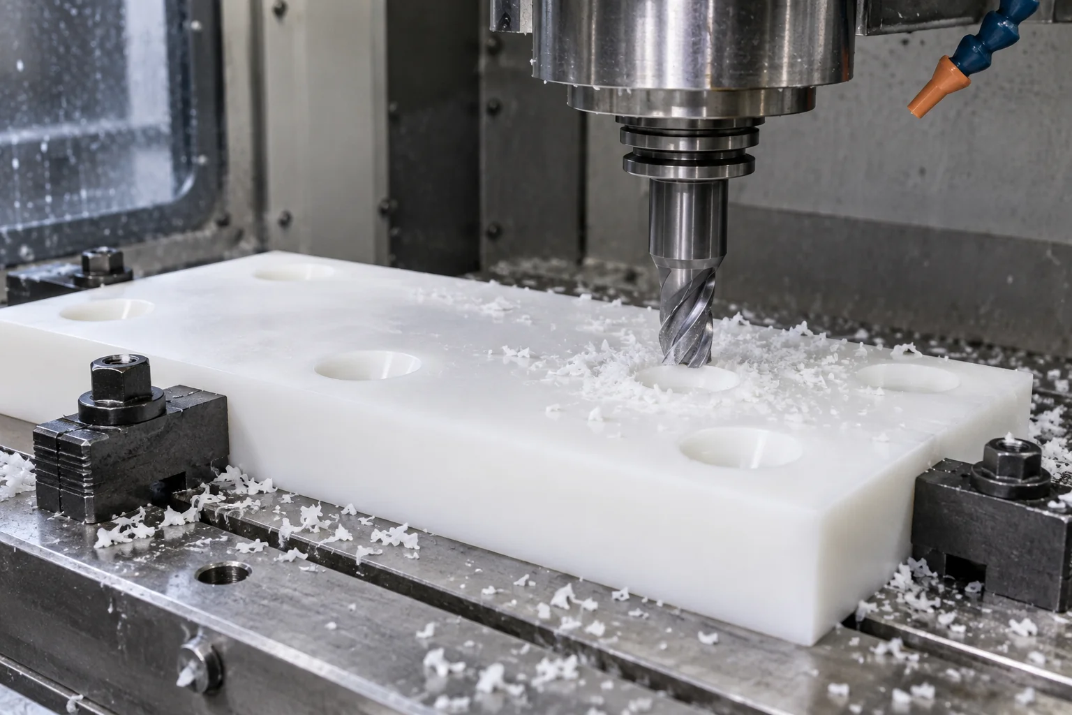
Machine the external profile, pockets, slots, V geometry and stepped faces while supporting the part.
Produce the custom mounting pattern and fastener clearance holes.
Machine drawing-defined recess diameter, depth and angle for the specified hardware.
Produce round wear discs, pads and special rotational parts where required.
Remove burrs and finish specified edges for installation and sliding contact.
Check thickness, hole locations, counterbore depth, profile and agreed flatness.
Evaluate plastic where low friction, replaceability, corrosion resistance and counterface protection matter. Consider metal where very high load, stiffness or temperature dominates.
| Factor | Plastic wear pad | Metal wear plate |
|---|---|---|
| Friction | Often low with a suitable polymer and counterface | Depends on alloy, surface and lubrication |
| Weight | Usually lower density | Usually higher density |
| Noise | Can reduce sliding noise | Contact can be noisier |
| Corrosion | Grade and chemical compatibility dependent | Alloy and coating dependent |
| High load | Stiffness and creep can limit use | Often better load and stiffness capability |
| High temperature | Grade-specific operating limit | Often more suitable, depending on alloy |
| Replaceability | Good when designed for access and retention | Good when designed for access and retention |
| Rail protection | Sacrificial polymer can protect the mating rail | An unsuitable contact pair can accelerate counterface wear |
These are screening comparisons, not universal rankings. Verify the actual contact pair, lubrication, temperature and failure mode. Replacing a metal plate with plastic may require changes to support, thickness, fastening and clearance.
Typical uses involve replaceable sliding or abrasive-contact surfaces. The equipment designer specifies loads, material suitability and the maintenance limit.
Conveyor wear pads, slide rails, chain wear pads and guides.
Drawbars, chain guides and sliding wear interfaces.
Boom wear pads, telescopic sliding structures and supports.
Guide blocks, slide tracks and replaceable contact pads.
Machine wear pads protecting rails, frames and moving assemblies.
Chute and hopper liner pads for abrasion zones.
Low-friction guide pads and plastic slide blocks.
Agree the drawing revision, reference state, sampling and report requirements before manufacture.
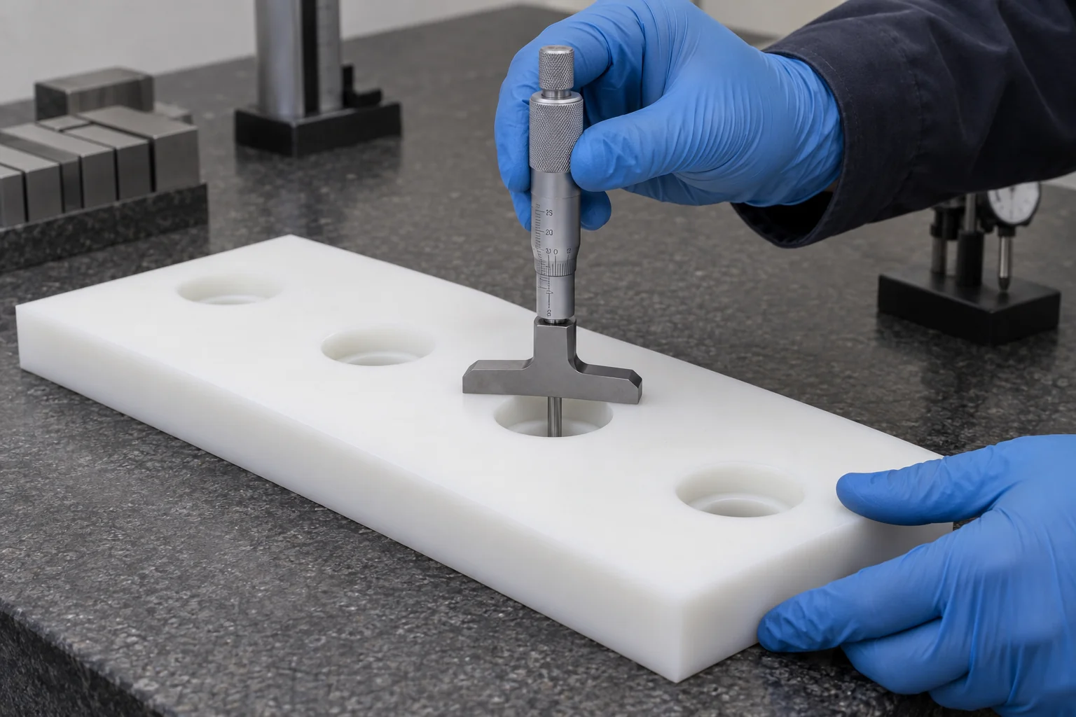
Check specified polymer, formulation, stock and requested documentation.
Distinguish original datums from worn, distorted or damaged surfaces.
Measure overall size and functional thickness in the agreed condition.
Check positions, diameters and installation interfaces.
Check depth, diameter, angle and the remaining supporting section.
Verify rail-contact profiles, curves, steps and grooves.
Check the agreed flatness, burrs, damage and sliding face.
Protect wear faces and keep sets, revisions and materials identified.
For long UHMW wear strips, control or record the inspection temperature where thermal growth affects acceptance. Avoid measuring soft parts under excessive force; confirm support and free-state dimensions.
Yes, where the original geometry can be established from a drawing, CAD model, dimensioned sketch, physical sample or sufficiently clear reference photographs. Restore the intended original wear surface rather than copying the worn condition.
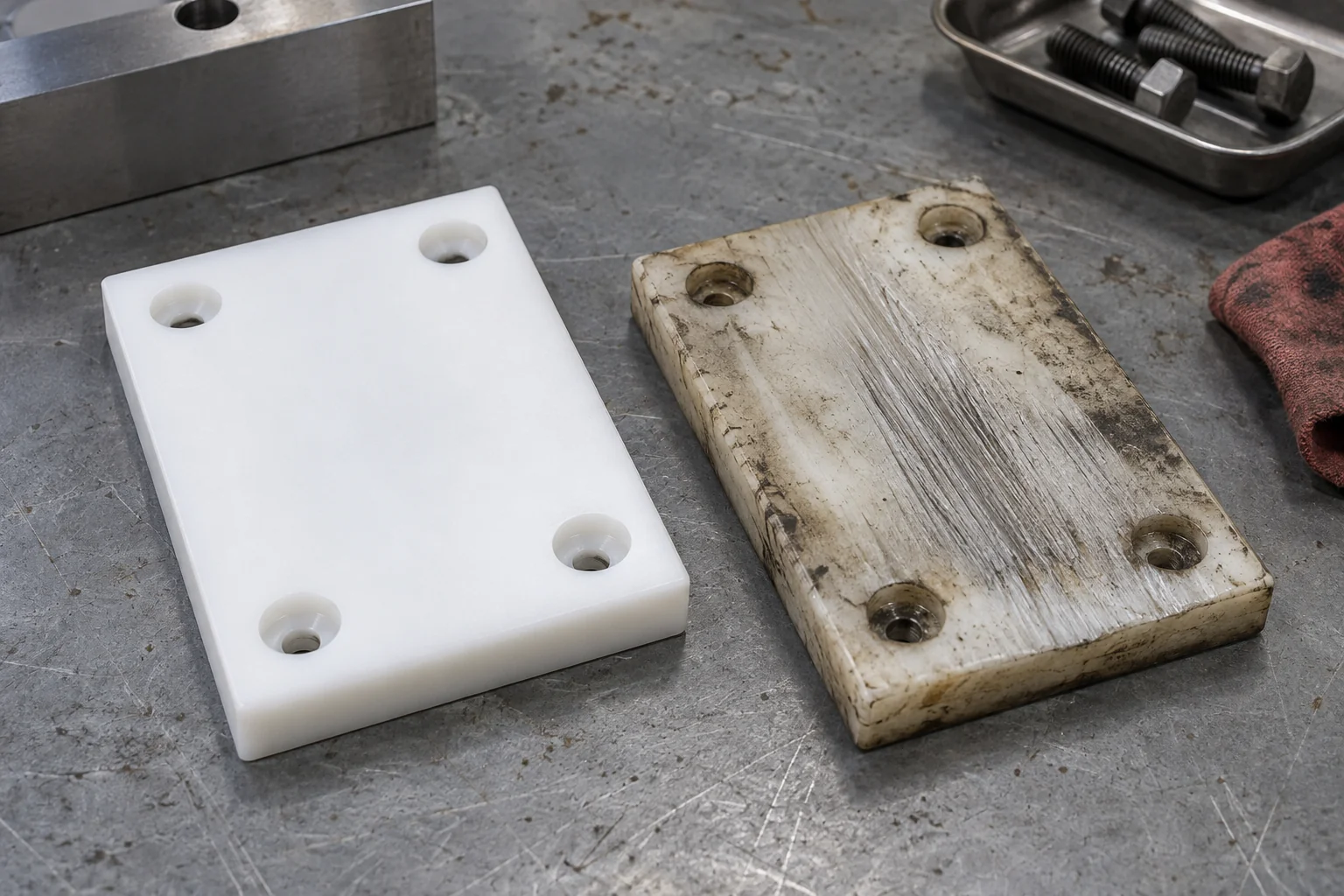
Reconstruct a documented replacement when the original spare is no longer supplied.
Confirm original thickness, mounting pattern and installed sliding clearance.
Separate intact datums from damage and establish the required contact profile.
Agree material and original geometry before releasing a replacement.
Document the machine interface and approve a locally manufactured replacement drawing.
Photos support review but may not establish scale, recess depth or the original wear face. Supply measurements, mating-part details or a physical sample where needed. We identify uncertain dimensions for approval before machining.
Material identification, load, original clearance and replacement limits should be confirmed. A worn sample does not by itself prove its original grade or thickness.
Maintenance replacements and new OEM designs both need a controlled part definition.
Confirm fit, hole pattern, material and service clearance before a repeat order.
Manufacture maintenance spares or specialized machinery sets to the approved drawing.
Control grade, dimensions, hole pattern, recess geometry and revision across recurring supply.
Bring the part geometry and the working conditions together in one manufacturing review.
Use released CAD, drawings and approved reconstructed dimensions.
Review the material against the sliding duty and dimensional requirements.
Produce wear faces, profiles and mounting patterns to the agreed drawing.
Coordinate counterbores, countersinks and the actual screw geometry.
Identify the new-part surface, wear limit and remaining supporting section.
Restore documented original geometry rather than reproducing wear.
Support maintenance replacements and controlled repeat orders.
Verify the agreed critical dimensions and service interfaces.
Answers about UHMW, Nylon, counterbores, wear allowance and maintenance replacements.
They provide replaceable sliding contact surfaces that reduce metal-to-metal contact and protect rails, booms, guides or frames. The equipment design determines load, clearance and replacement limits.
UHMW is often the first option for general abrasion and sliding; Nylon for greater stiffness and load, POM for dimensional control and PEEK for demanding temperature or chemical duty. The exact grade and contact conditions decide suitability.
Neither is always better. UHMW is commonly considered for abrasion, impact and low friction, while Nylon offers greater stiffness for loaded pads. Assess moisture, temperature, creep, speed and the counterface.
Specify enough initial thickness for load support plus a defined wear allowance. The minimum remaining thickness must preserve safe support, service clearance and fastener protection. No universal thickness fits all machines.
The recess must accommodate the screw head, intended wear allowance and required clearance while leaving adequate material beneath the head. Use the actual hardware dimensions and assess load and pull-through.
Sometimes, after an application review. Low-friction or self-lubricating polymers do not universally eliminate lubrication, and metal-to-plastic changes may require different support, thickness, retention or clearance. Follow the equipment specification.
Temperature changes dimensions, stiffness and creep behavior. Allow for thermal movement in long strips and define the inspection condition where fit is critical; include frictional heating in the material review.
Yes, where the intended original geometry can be established. We distinguish worn faces from original datums and seek approval of reconstructed thickness, profile and material before manufacture.
Provide length, width, new-part thickness, hole pattern, fastener size, counterbore diameter and depth, profile and wear allowance. Add counterface, load, speed, temperature and environment for a useful material review.
Yes, if the sample and supporting measurements establish the required replacement. Supply mating-part details or drawings for missing and worn dimensions, and approve the reconstructed part definition before machining.
YOUR WEAR FACE. YOUR MOUNTING PATTERN.
Upload your wear pad drawing, CAD model, sketch or reference photos and provide the material, length, width, thickness, hole pattern, fastener type, counterbore requirements, operating load and wear environment. TOPS Plastics can review the pad geometry and material before quotation.
Company, name, email and phone are required. Country, part number, quantity and drawing upload are optional. Include the technical information with your drawing package or send it by email.
info@tops-precision.comSTEP / STP / IGES / X_T / DWG / DXF / PDF or ZIP, maximum 10 MB. Larger packages can be shared by email. Agree confidential-file handling before sending sensitive drawings.