01
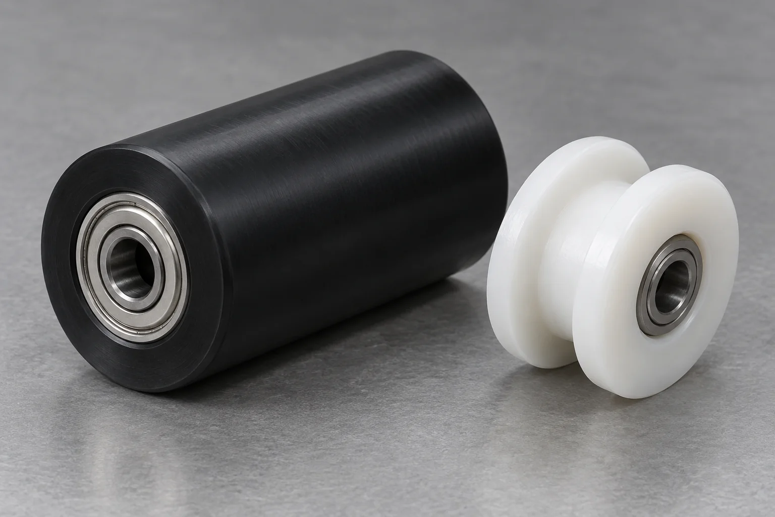
Plastic Rollers
Conveyors, guide mechanisms, automated equipment and belt tracking. Define profile, bearing interface, runout and contact load.
Explore component details →
MOTION · CONTACT · REPEATABILITY
TOPS Plastics manufactures custom CNC machined plastic components for robotic systems, automated production equipment, conveyors, end-of-arm tooling, inspection systems and precision motion assemblies. We machine POM/Delrin, PEEK, Nylon, UHMW, PTFE, PEI, PPS and other engineering plastics according to customer CAD files, functional requirements and production conditions.
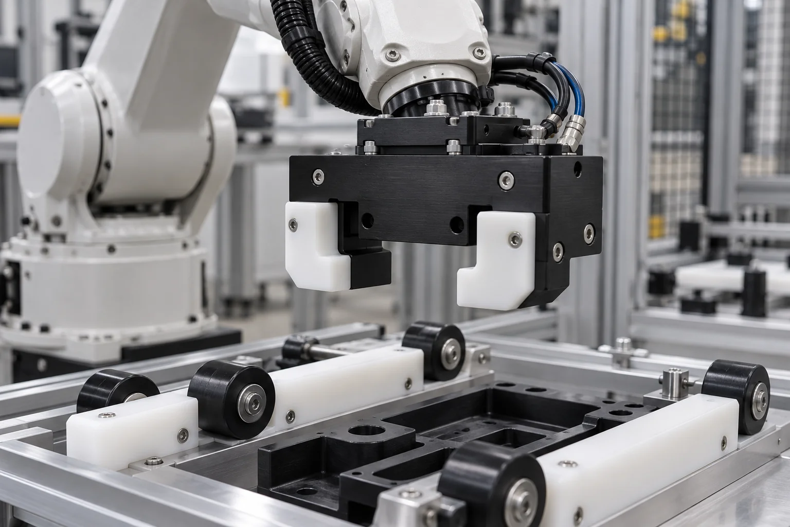
Build the component specification around motion, support, interfaces and the intended operating environment.
| Capability | TOPS Plastics |
|---|---|
| Typical parts | Rollers, bearings, bushings, wear pads, housings and fixtures |
| Materials | POM, Nylon, UHMW, PEEK, PTFE, PEI and PPS |
| Processes | CNC milling, turning, 5-axis machining, drilling and tapping |
| Key requirements | Low friction, wear resistance, repeatability and lightweighting |
| Production | Prototype, low-volume and recurring production |
| Input | STEP, CAD, 2D drawings and reference samples |
| Inspection | Drawing-based dimensional inspection |
| Hardware | Inserts, pins, bearings and fasteners where specified |
Explore motion, contact, tooling and equipment components. Connect the functional interface to its material and operating duty.
Conveyors, guide mechanisms, automated equipment and belt tracking. Define profile, bearing interface, runout and contact load.
Explore component details →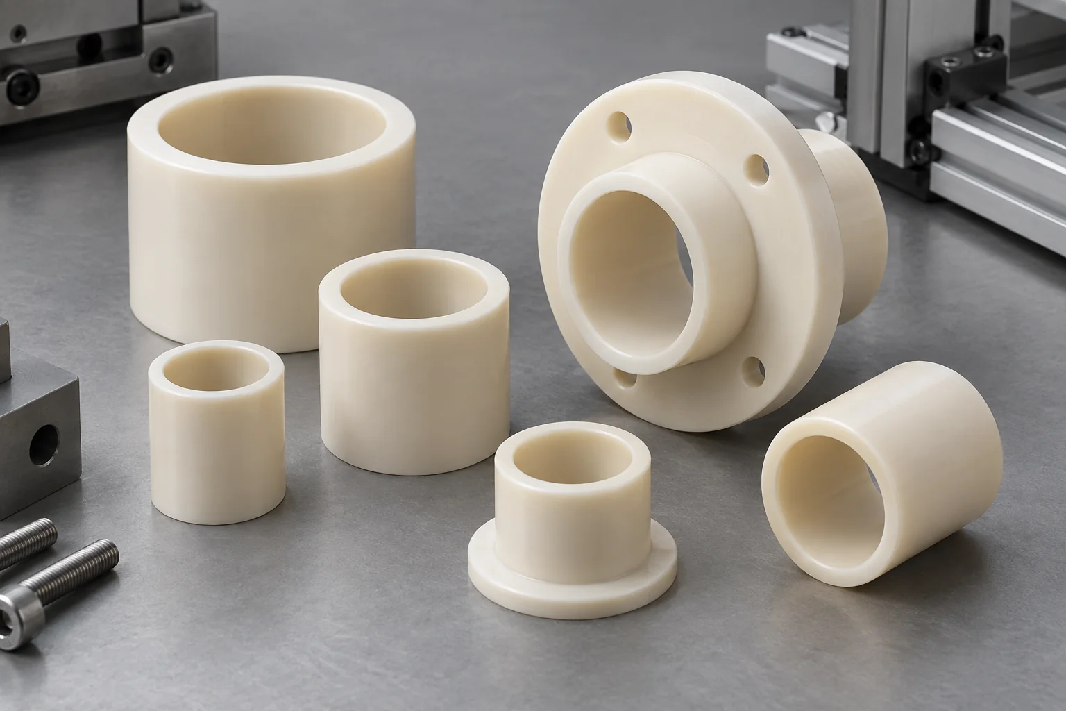
Low-friction pivots, sliding motion and rotating assemblies. Specify retained clearance, load, speed and the mating surface.
Explore component details →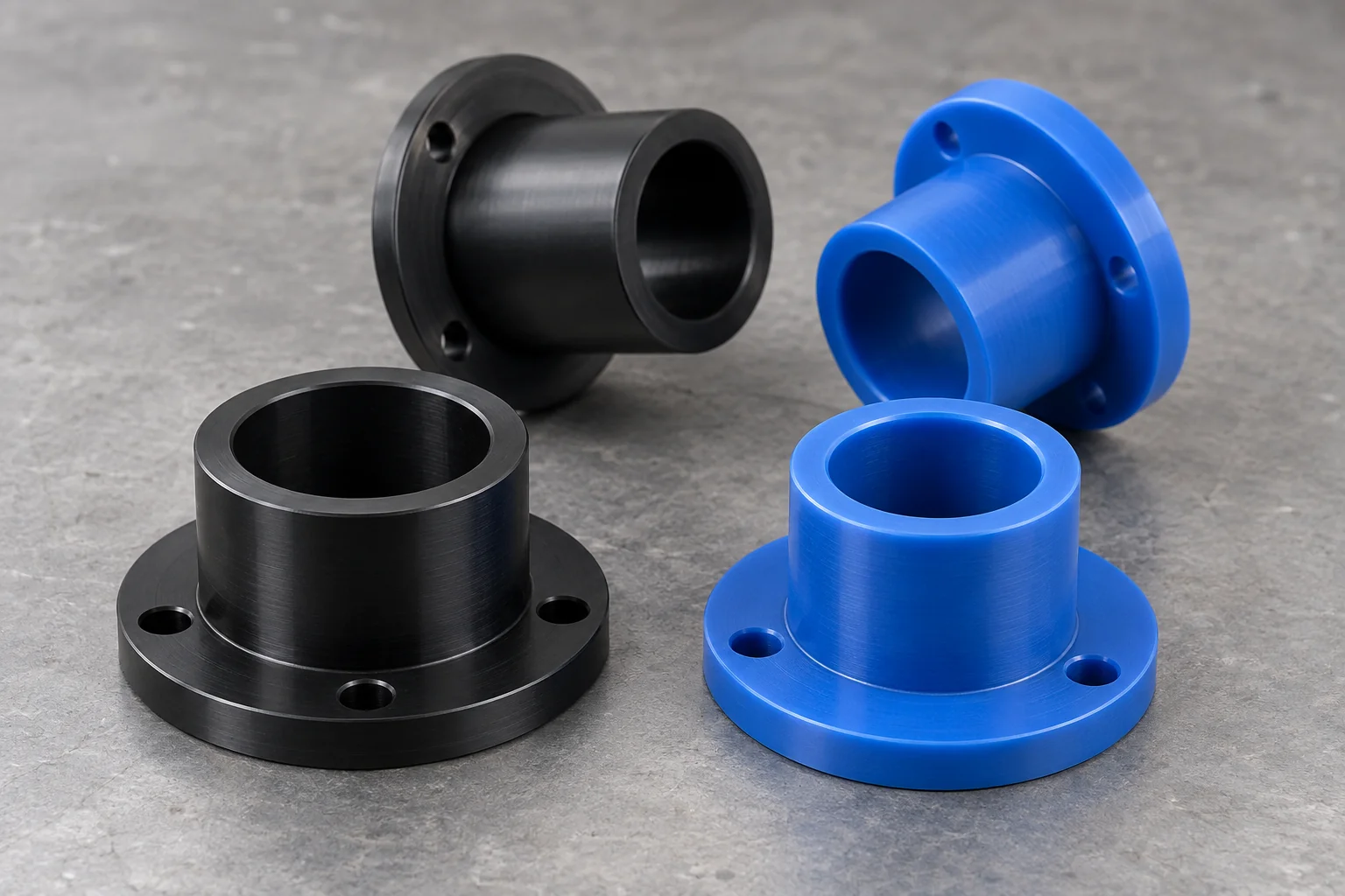
Shafts, pivots and guided-motion interfaces. Review support, lubrication, fit and temperature before selecting a grade.
Explore component details →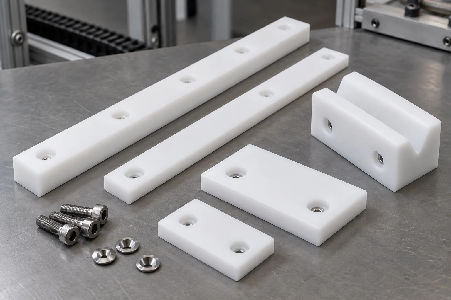
Linear slides, guides, robot motion assemblies and material handling. Define wear allowance, mounting recesses and replacement limits.
Explore component details →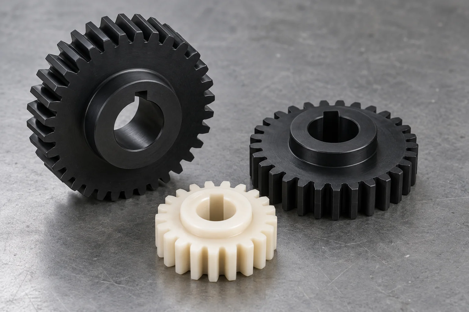
Actuators, indexing, motion transmission and drive systems. Supply tooth geometry, torque, speed, backlash and mating-gear details.
Explore component details →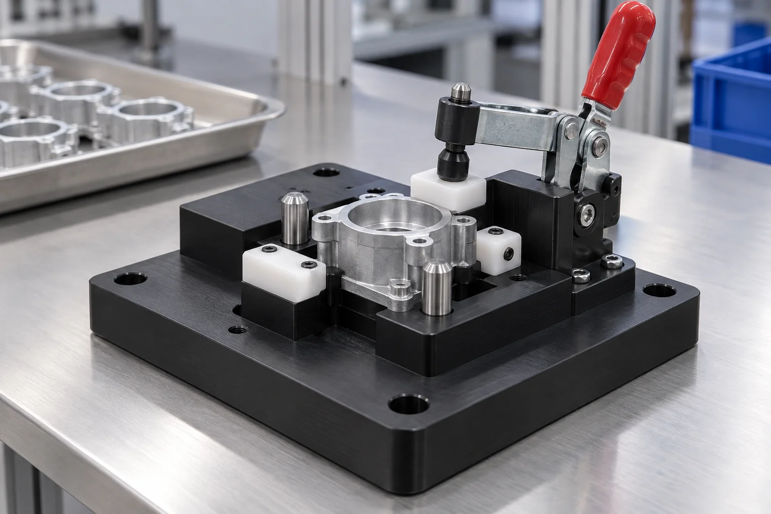
Assembly, positioning, inspection, robotic loading and poka-yoke. Establish datums, nest clearance, hardware and loading sequence.
Explore component details →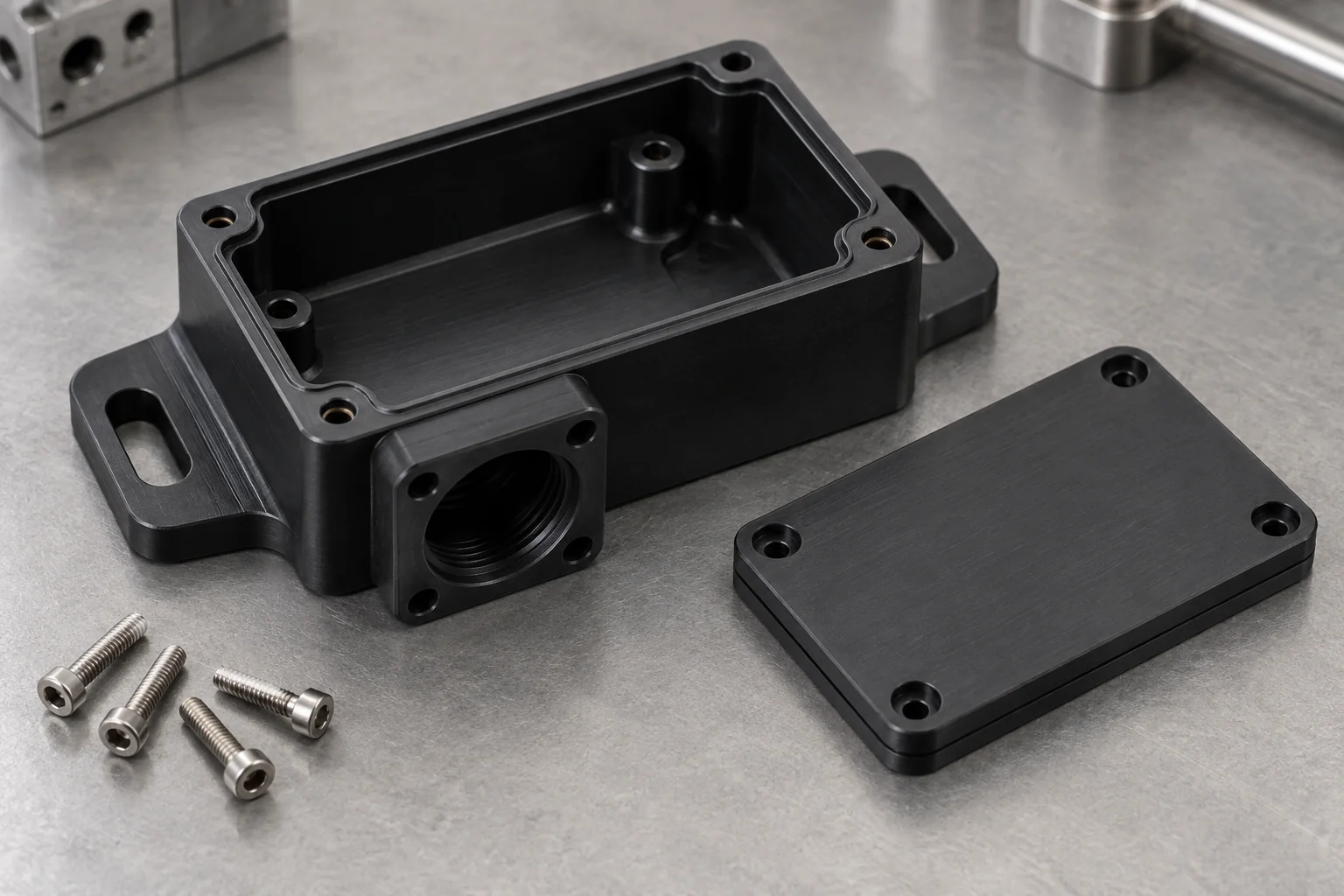
Motor, sensor, encoder and electronics bodies. Define alignment datums, connector openings, mounting load and cable access.
Explore component details →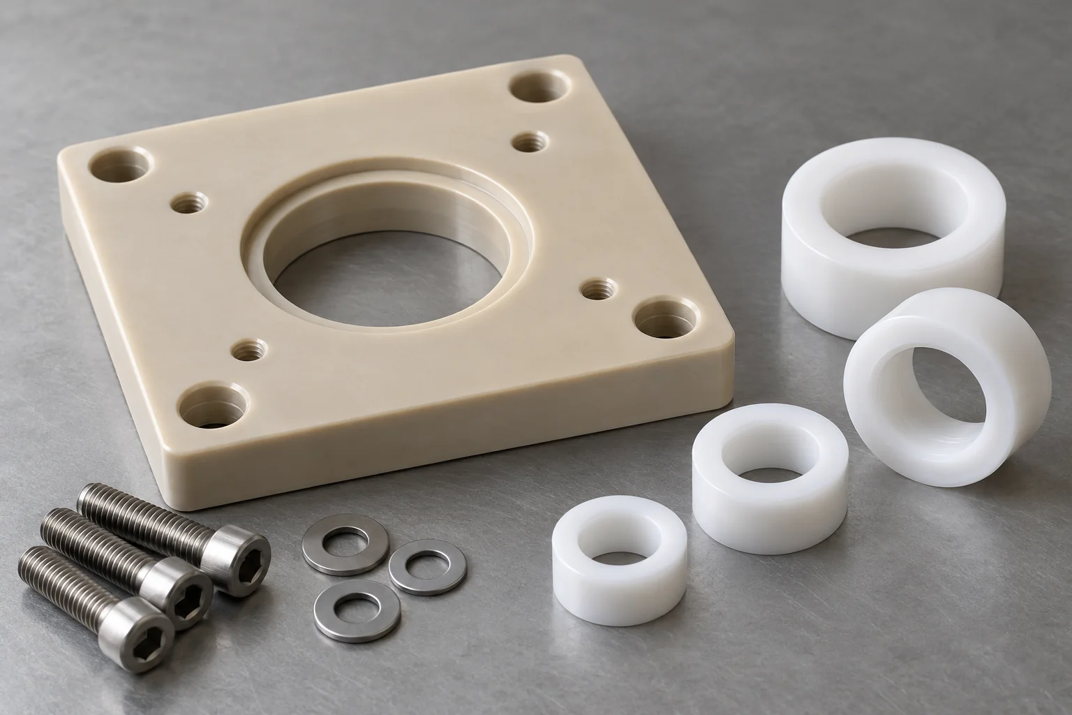
Electrical isolation, sensor spacing and control-equipment interfaces. Specify the grade, required electrical behavior and stack dimensions.
Explore component details →Plastic Spacers →Different system zones place different demands on a polymer. Connect the motion or handling problem to the actual part function.
Bushings, bearings, spacers, wear components and sensor housings. Balance friction, moving mass, repeatability and wear resistance.
Gripper fingers, nest blocks, vacuum tooling, locators and protective pads. Review stiffness, retention, contact pressure and changeover.
Rollers, wear strips, side guides, chain guides and spacers. Abrasion, impact, contamination, noise and mounting affect selection.
Jigs, fixtures, nests, locating blocks, guides and spacers. Define datum relationships and consistent loading without over-constraint.
Sensor housings, brackets, insulating blocks and optical mounts. Control alignment and access while reviewing temperature and electrical behavior.
Gripper parts, wear blocks, guide rails, rollers and lightweight fixtures. Consider cycle rate, product contact and repeatable positioning.
POM is often a starting point for precision interfaces, UHMW for wear and conveyors, Nylon for tougher loaded parts, and PEEK for demanding thermal or mechanical duties. Confirm the exact grade.
| Material | Main advantage | Application direction | Main consideration |
|---|---|---|---|
| POM / Delrin | Stability, machinability and low friction | Guides, gears and fixtures | Temperature, load and chemical exposure |
| Nylon | Toughness and wear resistance | Bearings, rollers and loaded guides | Moisture absorption and conditioning |
| UHMW-PE | Low friction and abrasion resistance | Wear strips and conveyor guides | Lower stiffness, creep and thermal movement |
| PEEK | Thermal, mechanical and chemical performance | Demanding motion components | Cost and grade-specific behavior |
| PTFE | Low friction and chemical resistance | Sliding and isolation interfaces | Creep and lower rigidity |
| PEI / Ultem | Electrical and thermal performance | Sensor and electronics supports | Chemical compatibility and required electrical data |
| PPS | Chemical and dimensional performance | Precision technical components | Fillers, brittleness and notch sensitivity |
| PET-P | Low moisture uptake and stability | Precision guides and mechanical parts | Temperature, exposure and actual grade |
Bushings, plain bearings, rollers, sliders, guide blocks and thrust parts need load, speed, shaft material, temperature, lubrication and service-life requirements reviewed together.
Contact pressure depends on load and supported area. Include peak, radial and axial loads and the actual mounting geometry.
Rotational, oscillating and linear motion produce different wear patterns. Provide speed, travel and reversals rather than a cycle count alone.
Steel, stainless, aluminum and coated shafts interact differently with polymers. Specify surface roughness, hardness and alignment.
Dry, grease, oil or process-fluid operation affects friction and wear. A suitable dry-running grade is not the same as any standard polymer.
Ambient and frictional heat affect stiffness, expansion and clearance. Check the assembled fit across the operating range.
A low friction coefficient does not predict service life by itself. Use relevant grade data and representative operating trials where duty is critical; confirm acceptable wear and replacement criteria before assigning a life target.
Gripper fingers, vacuum tool plates, part nests, locator blocks, jaw inserts, contact pads and changeover tooling can be machined to the workpiece and loading process.
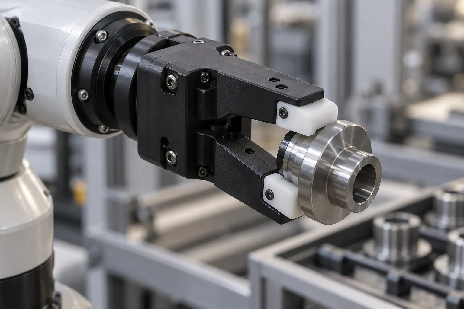
Reducing tool mass may free payload capacity and improve dynamic behavior. Robot limits and the full tool assembly still require review.
Suitable contact polymers can help protect finished workpieces. Pressure, debris, edge radii and cleanliness remain important.
Machine nests and contact contours from CAD with relief for part variation and access for loading.
Insulating grades may separate electronics or conductive workpieces. Specify documented static-dissipative behavior when that is required instead.
Renew worn jaw inserts or pads independently of the tool body, using repeatable locating and secure retention.
Lower end-of-arm mass can improve payload utilization, but stiffness, clamp force and part retention must be validated for the intended motion and acceleration. Specify the workpiece, center of mass, grip surfaces and any vacuum interfaces with the drawing.
Wear strips, chain guides, side guides, slide blocks, rollers, guide rails and wear pads provide controlled contact through repeated material movement.
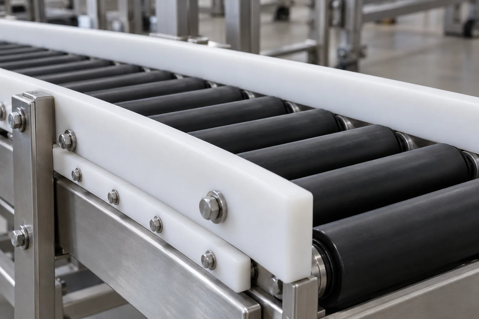
Review product and counterface materials, sliding speed and abrasive debris. UHMW, Nylon, POM or PEEK suit different duties.
Entry impacts, trapped particles and misalignment can change wear behavior. Design support and cleaning access around the application.
Long guides need allowance for thermal movement. Recess hardware so fasteners do not contact the moving surface.
Specify new thickness, minimum remaining section and replacement access. Retain sufficient support below counterbores and contact faces.
Sensor and encoder housings, connector bodies, spacers, insulators, PCB supports and cable guides need stable interfaces and suitable electrical behavior.
Standard grades of many polymers are insulating. Define required voltage, spacing and test conditions for the complete assembly.
Control mounting datums, bore fits and interface geometry so the sensor or encoder remains correctly positioned.
Specify heat exposure and any shielding requirement. Ordinary insulating plastic does not provide metal-like electromagnetic shielding.
Provide connector access, bend space, service openings and retained hardware. Review moisture and cleaning exposure where applicable.
ESD or static-dissipative behavior requires a documented material grade and an appropriate system arrangement. Black color and a general plastic description do not establish electrical performance.
Engineering plastics can reduce moving mass compared with metal in suitable assemblies. The benefit must be balanced against stiffness, creep, thermal expansion and retained part position.
Lower tool mass reduces payload consumption. Check the complete tool, hardware and workpiece mass against the robot envelope.
Reduced inertia can help acceleration, but support, vibration and deflection must remain within the positioning requirement.
Polymers may reduce mass in non-load-dominant components while adding electrical isolation or protective contact.
A metal replacement is not necessarily a one-for-one geometry substitution. Review section thickness, mounting points and sustained loads; no universal percentage reduction or energy-saving claim applies to every design.
Tolerance the functional interfaces controlling motion, locating, fit and alignment. Agree realistic limits for the grade, geometry and inspection state.
| Feature | Why it matters |
|---|---|
| Bore diameter | Bearing and shaft fit |
| Hole position | Assembly alignment |
| Roller runout | Smooth motion and contact |
| Spacer thickness | Stack height and clearance |
| Gear tooth geometry | Motion transmission and backlash |
| Fixture locator position | Part loading repeatability |
| Housing interface | Sensor or motor alignment |
| Flatness | Fixture and mounting stability |
Temperature, moisture, thin sections, clamping force and assembled fits can change dimensions. Specify GD&T, critical datums and the free or restrained measurement state where relevant. A dimensional report alone does not demonstrate dynamic system repeatability.
Service life depends on the complete contact system and operating cycle. Define acceptable wear, clearance change and the maintenance interval.
Contact stress changes with applied force, support area and alignment. Include peak loads and edge loading.
Motion generates frictional heat. Identify sliding, rotation or oscillation and the travel length.
Continuous running differs from intermittent cycles with cooling periods. Provide cycle rate and dwell time.
Roughness, hardness, coating and mating material affect friction and wear.
Dust, product fragments or abrasive particles can accelerate wear or damage a surface.
Heat affects stiffness, expansion, friction and retained clearance. Review both ambient and locally generated heat.
Lubrication and chemicals also affect the contact system. Use relevant material data and agreed testing for demanding duties; a standard grade name cannot establish unlimited life or maintenance-free operation.
Application-specific ESD, food-contact, cleanliness and environmental requirements can be reviewed during quotation.
Specify a documented static-dissipative grade, required resistance range, grounding arrangement and verification method where needed.
Provide particle, residue, handling and packaging specifications so feasibility can be confirmed.
Identify intended contact, temperature, cleaners and the exact supplier documentation required for the grade.
Specify chemicals, concentration, temperature, exposure duration and mechanical loading.
Review moisture, detergents, disinfectants, thermal cycling and protected interfaces.
ESD-safe, food-contact and cleanroom suitability depend on the exact material, process and acceptance requirements. They cannot be inferred from polymer family, appearance or a machining capability alone.
Define the operating motion and acceptance criteria before releasing the part for manufacture.
Use load, speed, support, lubrication and environment together rather than friction alone.
Focus on moving assemblies while retaining enough stiffness and supported section.
Establish locating references for fixtures, housings and sensor alignment.
Allow for thermal movement, moisture where relevant and creep under sustained load.
Separate high-wear pads, jaws and guides from the durable support structure.
Preserve assembly, connector and service clearance in housings and end tooling.
Review heat, wear, fatigue-sensitive geometry and maintenance access.
Include temperature, chemicals, moisture, particles and electrical requirements.
Select the machining route around the material, functional faces and approved hardware specification.
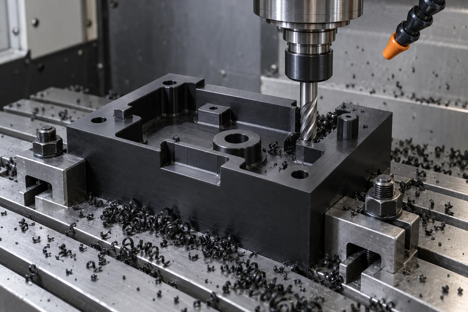
Machine fixture nests, housings, guides, brackets and wear blocks with defined locating and mounting features.
Produce bushings, rollers, spacers, bearings and rotational interfaces.
Use multi-axis access for complex end tooling and multi-face geometry where justified.
Create specified hardware holes, threads and machine interfaces.
Install agreed threaded inserts, bearings, locator pins or clamps to the assembly specification.
Verify critical motion, locating and fit features against the released drawing and inspection plan.
Plastic is attractive for mass, friction, protective contact and electrical isolation. Metal may be preferable where stiffness, structural load or temperature dominates.
| Factor | Engineering plastic | Metal |
|---|---|---|
| Weight | Usually lower for equivalent volume | Usually higher for equivalent volume |
| Friction | Suitable grades may reduce friction | Depends on pairing, finish and lubrication |
| Electrical isolation | Available with insulating grades | Typically conductive |
| Corrosion | Compatible grades resist many environments | Alloy, coating and media dependent |
| Stiffness | Lower; support and section matter | Generally higher |
| High load | Creep and contact stress require review | Often more suitable; geometry still matters |
| High temperature | Grade- and load-dependent limits | Often more suitable; alloy and condition matter |
| Non-marring contact | Good potential with clean suitable contacts | May need protective pads |
Hybrid construction can combine a metal frame with polymer bearings, guides or contact pads. Compare the whole assembly and validate retention, deflection and dynamic behavior rather than replacing materials by name alone.
These equipment categories connect component requirements to machine builders, integrators and production teams.
Joint, sensor and tooling components with application-specific loads and interfaces.
Lightweight fixtures and contact tooling; overall system safety remains part of the integrator evaluation.
Gripper fingers, nests and guides for repeatable handling.
Rollers, wear strips and guides for material flow.
Fixtures, spacers and locating parts for consistent workpiece positioning.
Precision nests and sensor supports with defined datums.
Guides, rollers and contact tooling matched to the product and cycle.
Insulating or documented ESD-related components where specified.
Agree functional features, inspection state and any mating-component checks before production.
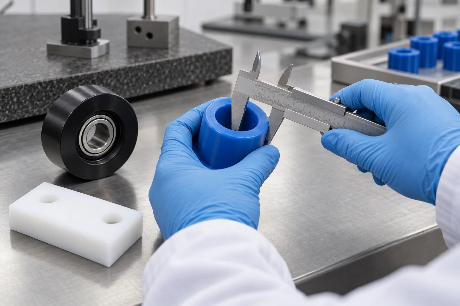
Confirm the specified grade and requested supplier documentation.
Align released revisions, datums and reportable features.
Measure fits under the agreed support and temperature conditions.
Check mounting and locating relationships to functional references.
Verify motion and stack-related features as specified.
Check agreed hardware, position, fit and retained interfaces.
Where mating components are provided, review seating and fit. Dynamic trials require a separately agreed scope.
Protect finished contact areas, bores and locating surfaces for shipment.
For repeat orders, maintain the approved drawing revision, controlled material grade, machining program and critical-dimension inspection requirements. Capture approved changes so repeated supply follows the released specification.
Move from concept geometry to consistent equipment supply through agreed evaluation and release stages.
Validate geometry, fit, motion concept and material direction with representative mating parts.
Evaluate wear, repeatability and cycle behavior in the intended machine conditions.
Supply specialized automation equipment and subsystem builds to released drawings.
Maintain approved material, drawing revision, machining program, inspection and packaging requirements.
Select around the complete motion system: load, speed, cycle frequency, counterface, temperature, friction, stiffness, moving mass and environment.
Review POM, UHMW, Nylon, PEEK, PTFE, PEI and PPS against the specified duty.
Connect roller, gear, bearing, bushing and wear-part requirements to the relevant process.
Machine jigs, nests, fixtures and custom contact tooling from customer CAD.
Manufacture multi-face parts, fit-critical interfaces and custom geometry.
Support machine builders and integrators through development and recurring orders.
Agree critical-feature checks and acceptance requirements for each component scope.
Move from application requirements to the detailed product page for geometry, interfaces and drawing preparation.
Direct answers about materials, grippers, motion, dry-running conditions, tolerances and repeat supply.
POM, Nylon, UHMW, PEEK, PTFE, PEI, PPS and PET-P are common candidates for different functions. Choose the grade for motion, load, temperature, environment and required evidence.
POM combines useful machining, dimensional and low-friction properties for guides, gears and fixtures. Load, chemical exposure and operating temperature still require review.
UHMW is often considered for low-friction and abrasion-resistant guides. Its lower stiffness, creep and thermal movement must be considered in the mounting and precision requirement.
PEEK may be considered when temperature, mechanical or chemical demands justify a higher-performance material. Compare the actual grade against the application rather than cost or family name alone.
Yes, suitable polymer components can reduce moving mass. Stiffness, retention, creep and thermal movement must still satisfy the complete assembly requirements.
POM and UHMW are common starting candidates for machined jaws and protective contacts. Heat, chemicals, grip force and workpiece finish may justify other grades.
Some grades and designs can operate dry within defined conditions. Dry-running suitability depends on material, load, speed, counterface, temperature and acceptable wear; it is not universal.
Prioritize bearing fits, locator positions, runout, stack thickness and sensor alignment. Agree realistic limits for the grade, geometry and inspection state.
TOPS Plastics can review drawing-based polymer tool plates, gripper fingers, nests and contact inserts for machining. Complete robot integration and dynamic retention validation need defined customer requirements.
Yes, prototype, pilot and recurring equipment components can be reviewed. Supply approved material, released CAD, quantity and functional acceptance requirements.
MOTION. LOAD. SPEED. CYCLE RATE.
Upload your component drawing or CAD model and specify the material, quantity, equipment type, load, speed, duty cycle, mating components, operating environment and critical tolerances. TOPS Plastics can review the geometry, material and machining approach before quotation.
Company, name, email and phone are required. Country, part number, quantity and drawing upload are optional. Include technical requirements in the drawing or email; combine CAD and supporting files into one ZIP if useful.
info@tops-precision.comSTEP / STP / IGES / X_T / DWG / DXF / PDF or ZIP, maximum 10 MB. Larger packages can be shared by email. Agree confidential-file handling before sending sensitive drawings.