01
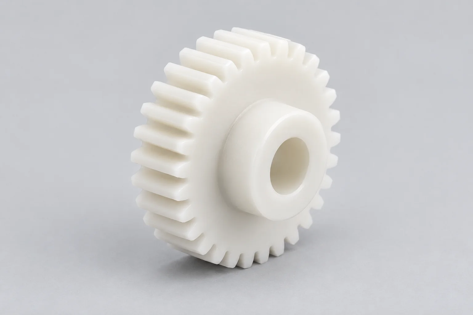
Plastic Spur Gears
Straight teeth for parallel shafts and straightforward power transmission. Specify module or DP, pressure angle, tooth count and the mating gear.
Discuss this gear →
ENGINEERED FOR THE MESH
TOPS Plastics manufactures custom plastic gears and precision power-transmission components from POM/Delrin, Nylon, PEEK, PPS, PEI and other specified engineering polymers. We review your drawings, CAD models and application requirements together: tooth geometry, bore and hub dimensions, backlash, load, speed and operating environment.
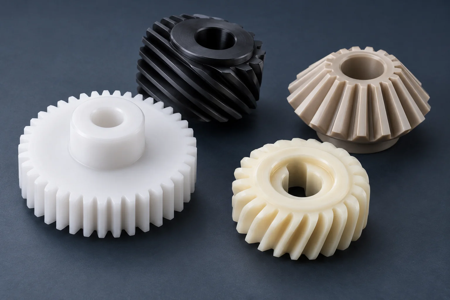
Start with the functional gear specification. Geometry, material grade and acceptance requirements are reviewed before the manufacturing route is agreed.
| Capability | Project scope |
|---|---|
| Gear types | Spur, helical, bevel, worm wheels, racks, miter, pinion and special profiles, subject to geometry review. |
| Materials | POM, Nylon, PEEK, PPS, PEI and other specified polymers; exact grade and fillers matter. |
| Machining | CNC turning of blanks, tooth machining and secondary milling using a strategy suited to the gear. |
| Features | Bores, hubs, keyways, splines, flats, slots, mounting holes and appropriate inserts. |
| Input | 2D drawings, 3D CAD and reference samples. Samples require an agreed reconstruction and acceptance specification. |
| Production | Prototype, low-volume and repeat production with controlled drawing revisions. |
| Inspection | Functional tooth geometry, bore relationship, runout and critical drawing dimensions with an agreed method. |
| Customization | Module or DP, tooth count, pressure angle, helix, face width, hub and bore; feasibility reviewed individually. |
Explore the gear geometry that matches your transmission. Each component is reviewed against its mating part, mounting features and duty.
Straight teeth for parallel shafts and straightforward power transmission. Specify module or DP, pressure angle, tooth count and the mating gear.
Discuss this gear →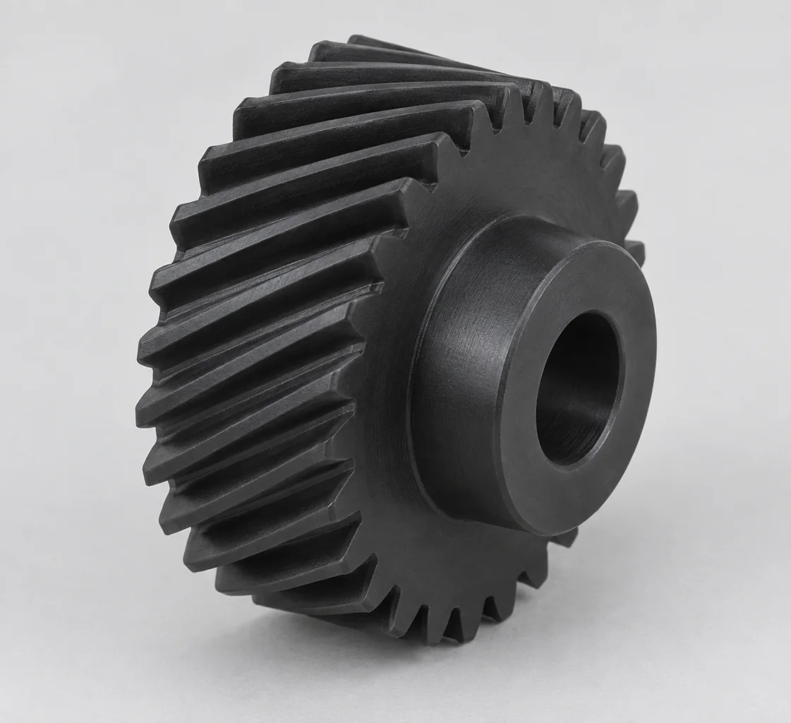
Angled teeth provide progressive engagement and can reduce noise. Define helix angle and hand, and allow for axial thrust in the shaft supports.
Discuss this gear →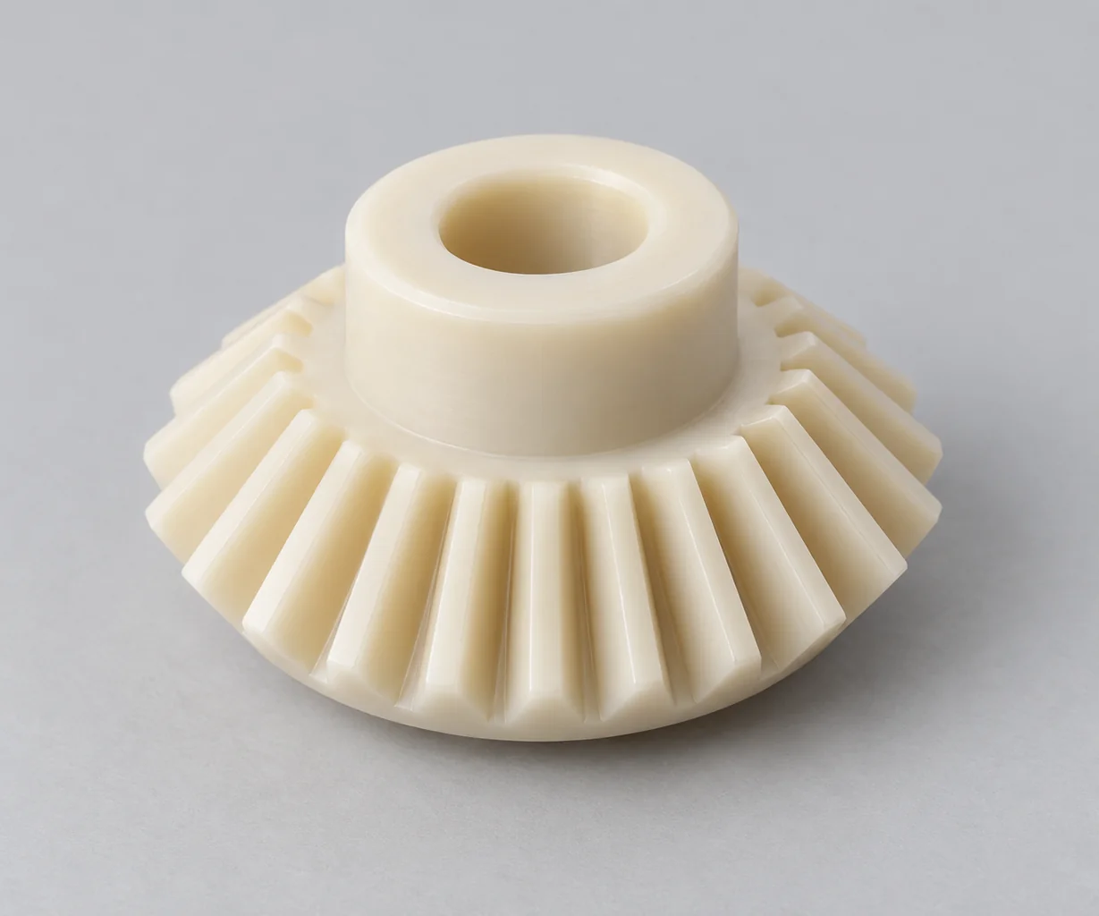
Conical tooth geometry transmits motion between intersecting shafts. Provide shaft angle, ratio, mounting distances and mating geometry.
Discuss this gear →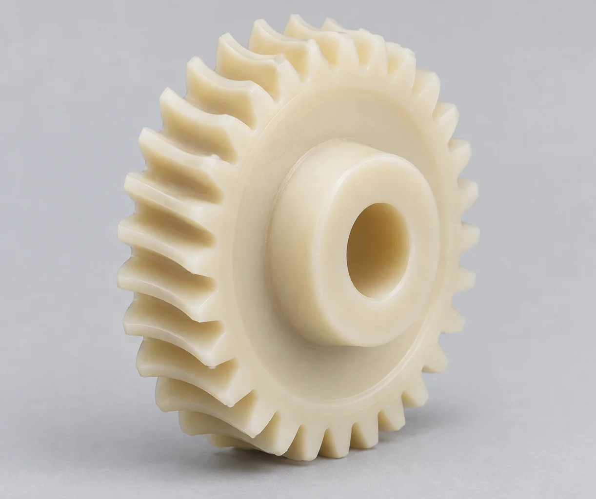
Compact reduction drives using a worm and a compatible wheel. Review sliding contact, heat, lubrication, worm starts and lead; self-locking is not assumed.
Discuss this gear →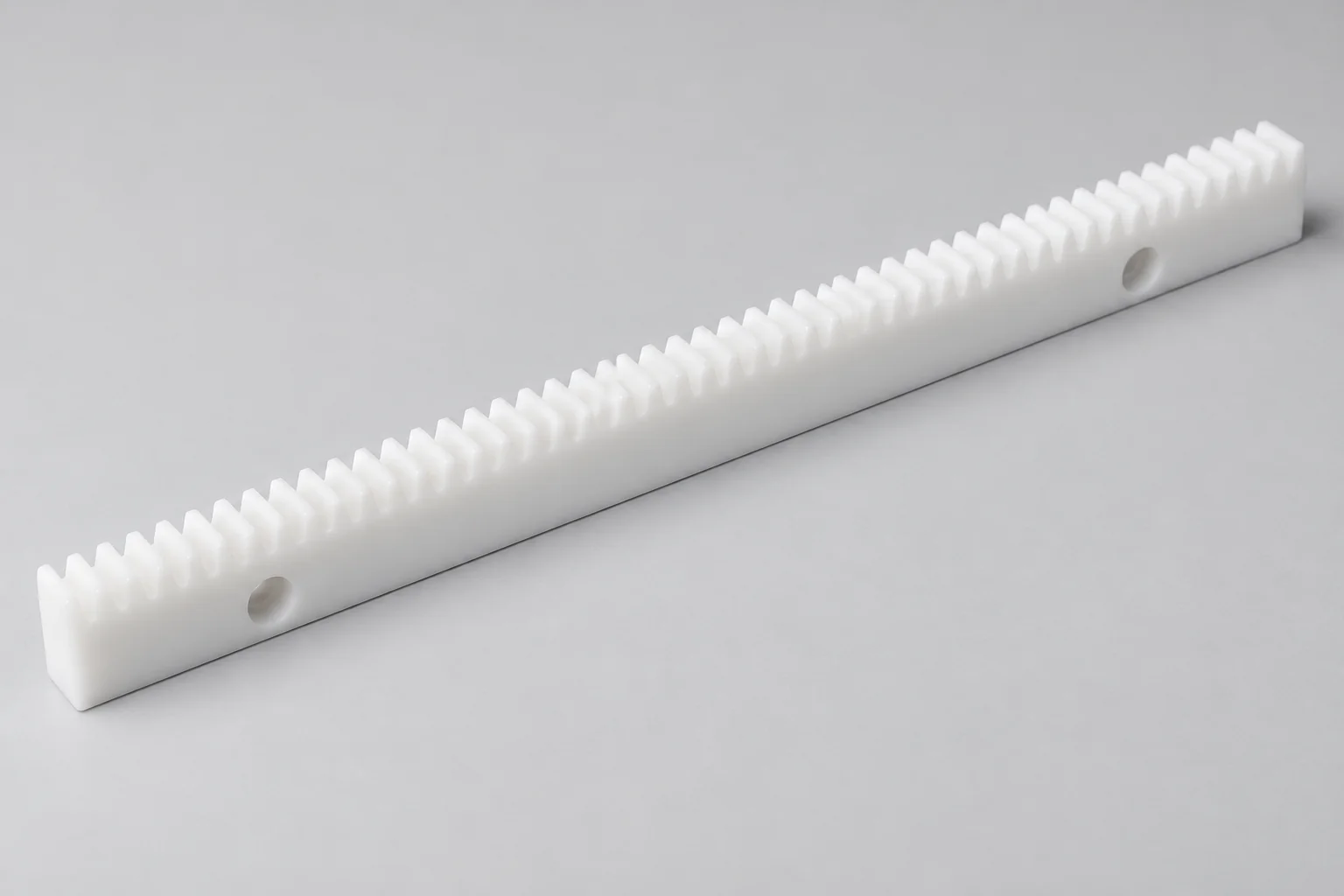
Toothed linear bars convert pinion rotation into travel. Define tooth pitch, overall length, mounting holes, alignment and joining requirements.
Discuss this gear →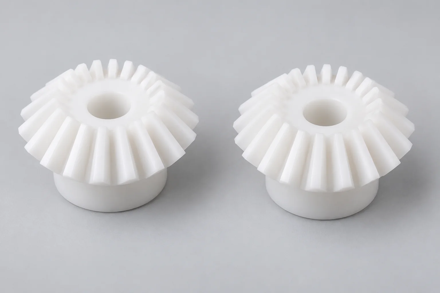
Matched bevel gears for a 1:1 ratio, commonly between right-angle shafts. Confirm the shaft angle, mounting arrangement and axial location.
Discuss this gear →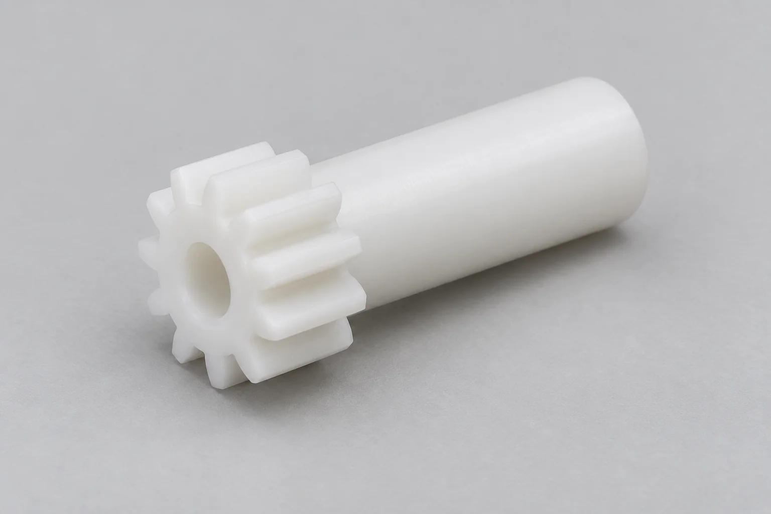
Small gears for larger wheels or racks. Tooth-root strength, tooth count, bore size and hub proportions need particular attention.
Discuss this gear →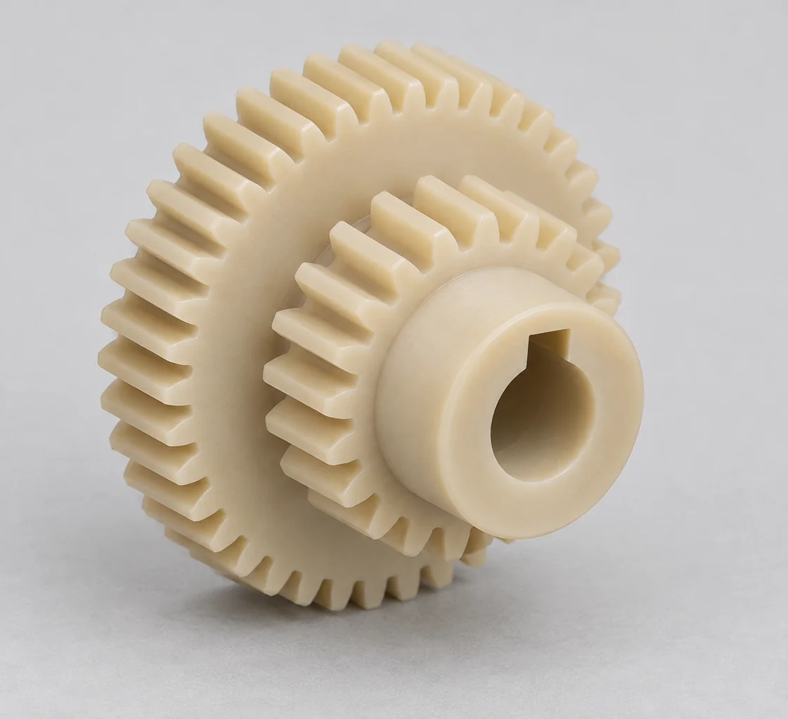
Compound stages, internal gears, timing gears, nonstandard bores, inserts and integrated hubs are reviewed to drawing. Internal and special profiles depend on tool access and inspection feasibility.
Discuss this gear →Plastic gears are toothed power-transmission components made from engineering polymers. They can suit mechanisms where lower mass, reduced operating noise, corrosion resistance, electrical isolation or limited lubrication is valuable.
The teeth transmit motion and load through a mating gear, rack or worm. The tooth system and mounting arrangement must be compatible across the pair.
Performance depends on stiffness, moisture response, thermal expansion, wear, backlash, mating material and duty cycle as well as tooth shape. A plastic gear needs an application-specific design review.
These advantages are design opportunities. Each depends on the selected polymer, mating component and operating conditions.
Polymer tooth contact can reduce transmitted noise in a well-aligned gear train. Tooth accuracy, backlash, speed and the housing still influence sound.
Lower component mass can help compact actuators and moving assemblies. Check stiffness and inertia requirements alongside weight.
Polymers do not form metallic rust. Compatibility with the actual cleaning agents, chemicals and temperature must still be checked.
Some engineering polymers support reduced-lubrication operation. Dry-running suitability requires a load, speed, temperature and wear review.
Unfilled insulating grades can help selected instruments and electrical mechanisms. Conductive fillers may change electrical behavior.
Machining supports development parts, small batches and nonstandard geometry without dedicated injection-mold tooling.
POM is often a useful starting point for precision gears; Nylon is a candidate for tough or shock-loaded mechanisms, and PEEK for more demanding temperature or chemical conditions. Select the grade from the complete duty profile.
| Material | Main strength | Main risk | Typical use |
|---|---|---|---|
| POM / Delrin | Good machinability, low friction and dimensional stability. | Load and temperature limits; grade-dependent wear. | Precision gears and compact transmission parts. |
| Nylon / PA | Toughness, impact resistance and useful wear behavior. | Moisture uptake can alter dimensions and stiffness. | Industrial gears where conditioning and mesh clearance are controlled. |
| PEEK | High-temperature and chemical capability relative to many common polymers. | Higher cost; actual load-bearing capability depends on grade and temperature. | Critical-duty gears after thermal and tribological review. |
| PPS | Chemical resistance and thermal dimensional stability. | Brittleness and notch sensitivity; filler effects on the mating surface. | Technical mechanisms with controlled tooth-root loading. |
| PEI / Ultem | Heat performance and electrical properties. | Wear capability needs particular review; not a default tribological choice. | Specialized mechanisms where the grade meets the service conditions. |
| UHMW | Abrasion resistance and low friction. | Low stiffness, creep and dimensional control limitations. | Coarse, low-load gearing where precision demands allow. |
Delrin is a POM trade name, and Nylon covers several polyamide families. Specify the supplier designation, conditioning state and any reinforcement or lubricant filler rather than relying on the family name alone.
Filled grades can change stiffness, expansion, wear and mating-surface abrasion. Food or medical use requires documentation for the exact material and application; the polymer family alone establishes no approval.
A quotation needs a defined tooth system and mounting interface. Review these parameters together with the mating part and assembly datums.
| Parameter | Definition required |
|---|---|
| Module / Diametral Pitch | Specify the tooth-size system and units. For helical gears, identify normal or transverse values. |
| Number of teeth | Provide each gear tooth count and the required transmission ratio. |
| Pressure angle | Specify the reference pressure angle and its normal/transverse basis where relevant. |
| Helix angle | Define angle and right- or left-hand helix; consider axial force. |
| Face width | Specify the working tooth width and the shaft alignment assumptions. |
| Bore diameter | Define shaft fit, datum axis and inspection condition. |
| Hub diameter | Define hub diameter, projection, mounting face and wall thickness. |
| Keyway / spline | Provide the applicable profile, dimensions, orientation and torque requirement. |
| Set-screw hole | Define size, location and thread; assess hub stress and retention. |
| Flange / web geometry | Review stiffness, weight, tool access and mounting features. |
| Metal insert | Review material, retention method, thermal mismatch and torque path. |
| Tooth modifications | Provide profile shift, tip relief or other changes explicitly on the specification. |
Backlash must allow the intended mesh to run as temperature, moisture, load and assembly dimensions change. Too little can cause binding and heat; too much can increase lost motion and impact when direction reverses.
Review the gear pair, shaft supports and housing together.
Working clearance between mating tooth flanks is distinct from tooth-tip clearance, axial movement and bearing play. State the measurement direction, assembly condition and acceptance range.
Shaft spacing and its tolerances influence working backlash and contact. Include bearing location, shaft deflection, housing expansion and mounting variation.
The gears and housing can expand at different rates. Review both cold-start and running conditions, including the material pair and operating tooth temperature.
Nylon in particular can change size and stiffness with moisture uptake. Define conditioning, storage and service humidity before agreeing inspection and mesh requirements.
There is no universal plastic-gear backlash value. The required allowance depends on tooth geometry, module, material pair, temperature range, moisture exposure and the assembly tolerance stack. A room-temperature fit check alone does not establish a reliable operating mesh.
Review the entire duty profile. Torque capacity or life cannot be inferred from polymer name, outside diameter or an isolated maximum material temperature.
Peak, continuous, start-up and reversing torque impose different tooth-root and hub loads. Include shock events, stalls and overload protection.
Speed affects sliding, frictional heating and wear. Provide rotational speed and pitch geometry for the relevant gear pair.
Continuous duty, intermittent operation and repeated starts produce different heat histories. Include operating duration, pauses and expected life.
Plastic-to-plastic and plastic-to-metal pairs can behave differently. Specify the mating material, hardness where relevant and tooth-surface condition.
Dry, grease or oil service changes friction and heat generation. Check lubricant compatibility, replenishment and possible contamination.
Ambient temperature and tooth-contact temperature are different. Heat changes stiffness and wear; evaluate the actual thermal duty and validate under representative conditions.
Treat the tooth form, material and mounting system as a single design problem. These eight checks help prepare a useful engineering drawing.
Review polymer stiffness, creep, expansion and wear before substituting a plastic part into an existing metal gear train.
Identify plastic, steel, brass or another mate; include its tooth specification and surface condition.
Include temperature, moisture, runout and manufacturing variation in the operating clearance review.
Reduce root stress concentration while preserving mating-tooth clearance. Avoid an unspecified sharp root.
Review shaft alignment and support. Increasing face width does not automatically deliver uniform load sharing.
Press fits, keyways and set screws can distort or overstress a polymer hub. Review assembly force and torque transmission.
Include torque, speed, duty cycle, temperature, chemical exposure, humidity and lubrication.
Tip relief and profile adjustments may help selected duties. Specify the intended load range and verify the modified mesh rather than assuming a universal correction.
The process follows the gear geometry and required inspection. Tool access, tooth size and material behavior are reviewed before a cutting strategy is selected.
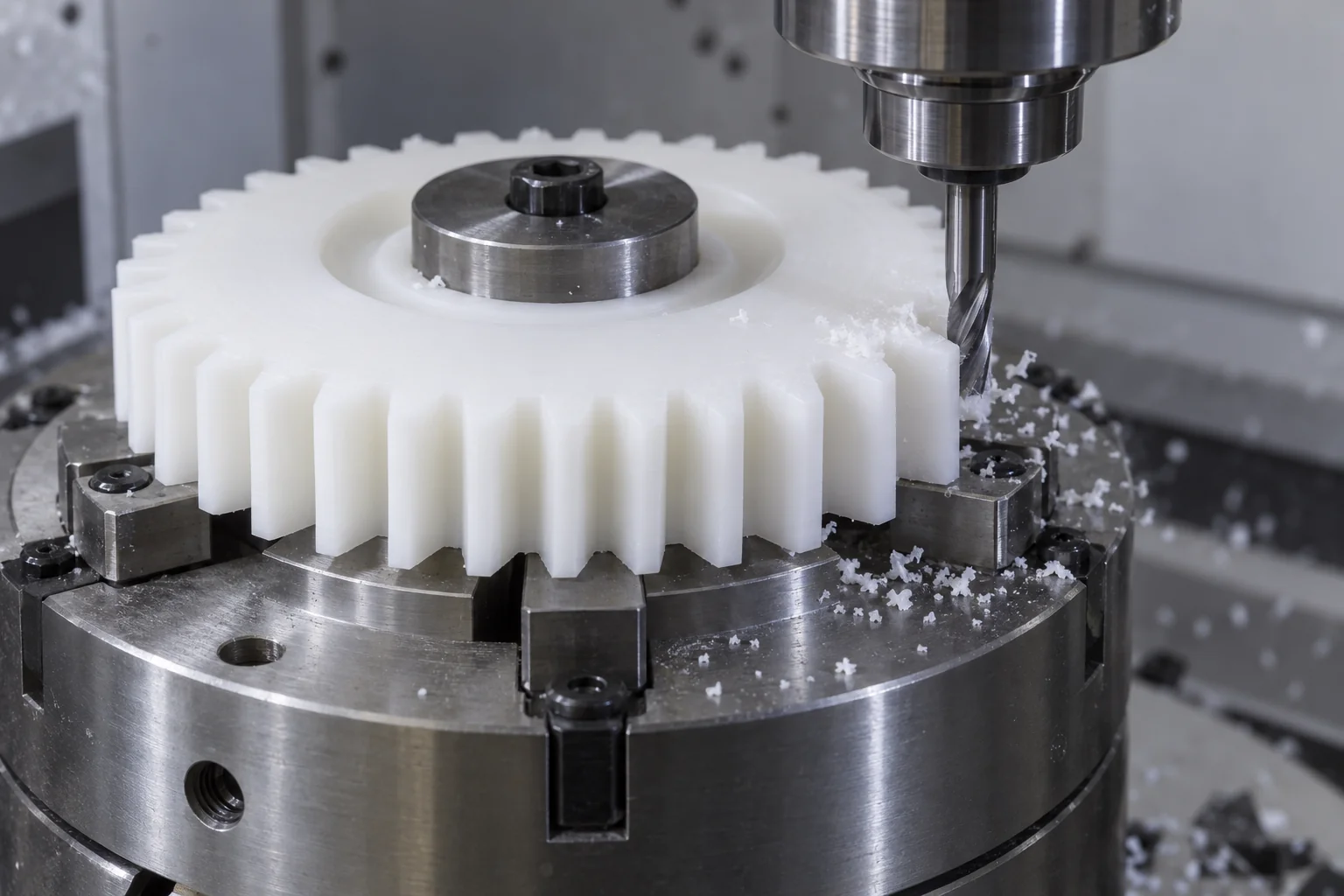
Create the bore, hub, reference faces and concentric blank features that establish the datum relationship.
Use a suitable tool and indexing or multi-axis strategy for the specified profile. Complex teeth, fine pitches and internal forms require feasibility review.
Machine keyways, flats, slots, holes and anti-rotation features while controlling their relationship to the bore and teeth.
Remove burrs without rounding functional flanks or altering the root and tip geometry.
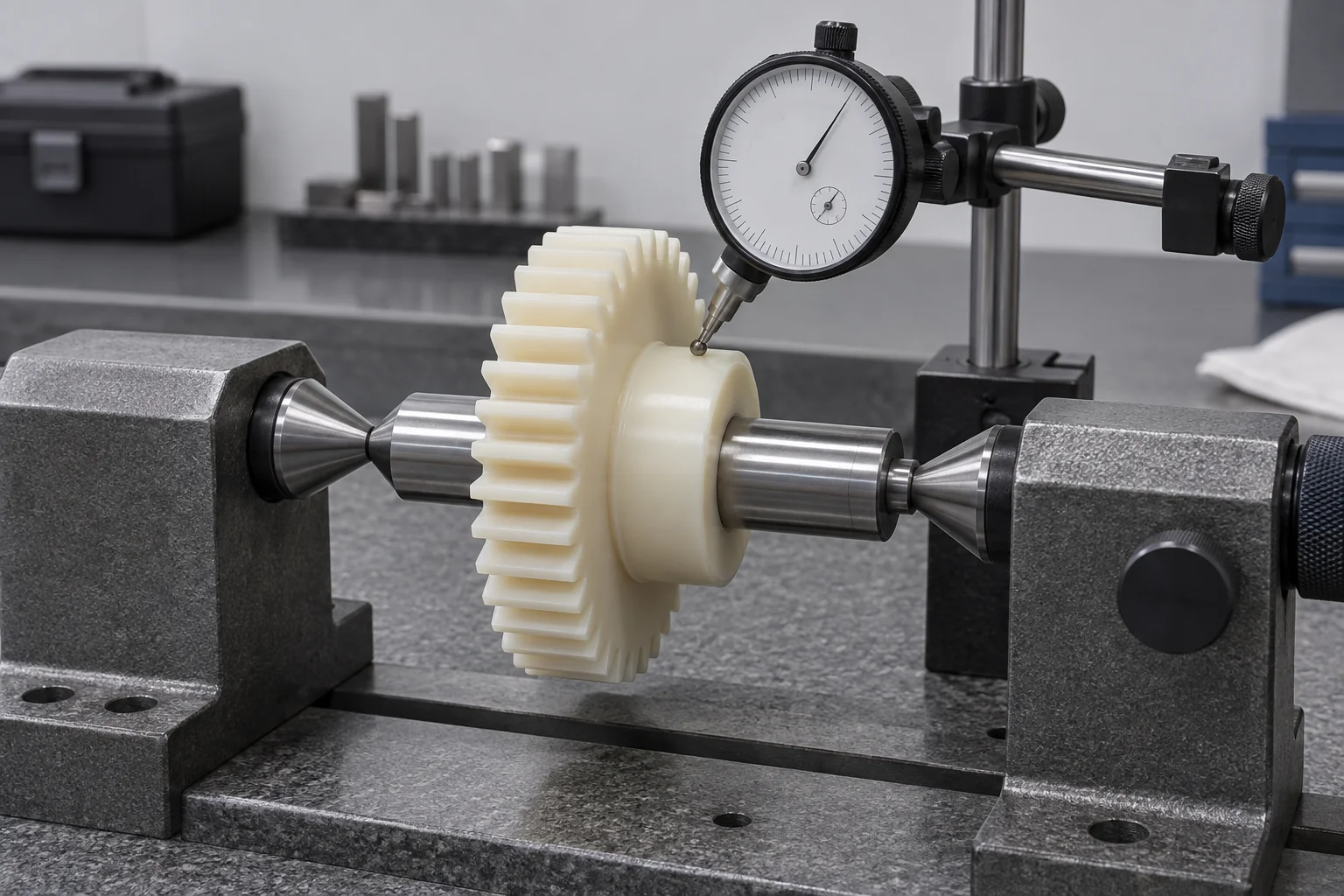
Verify agreed functional dimensions and condition. Confirm measurement methods and any specialized gear metrology before accepting a precision-grade requirement.
Tooth geometry and its relationship to the bore often matter more than general outside dimensions. The inspection plan should address mesh, shaft fit and motion under the agreed temperature and conditioning state.
| Feature | Why it matters |
|---|---|
| Bore diameter | Controls shaft fit; define measurement temperature and conditioning. |
| Bore-to-tooth concentricity | Connects the mounting axis to the functional tooth pattern. |
| Runout | Influences variation in mesh and backlash through a revolution. |
| Tooth thickness | Affects working backlash; agree the specified measurement method. |
| Pitch consistency | Influences engagement and motion quality. |
| Face width | Defines the available contact width and load distribution. |
| Hub geometry | Controls mounting position, support and interface alignment. |
| Keyway / insert location | Controls torque transmission, orientation and local hub stress. |
Required tolerances are assessed against material, tooth geometry, size, process and measurement feasibility. Submit the drawing for a tolerance review. A generic dimensional tolerance is not a gear accuracy grade.
Specify any DIN, ISO or AGMA requirement explicitly. Specialized profile, lead, pitch or composite testing and its acceptance report must be agreed before order confirmation; no unverified gear-grade certification is implied.
Choose plastic for an appropriate combination of low noise, low mass, corrosion resistance or reduced lubrication. Metal may be preferable where high load, stiffness or thermal performance dominates.
| Factor | Plastic gears | Metal gears |
|---|---|---|
| Weight | Usually lower for comparable geometry. | Usually higher; alloy and geometry dependent. |
| Noise | Can be lower with suitable material and mesh design. | Depends on tooth accuracy, mesh, lubrication and housing. |
| Corrosion | Polymer-dependent chemical resistance; no metallic rust. | Alloy, coating and environment dependent. |
| Lubrication | May be reduced in a validated design. | Often required; application dependent. |
| Load capacity | Limited by stiffness, heat, creep and tooth stress. | Often better suited to higher loads and stiffness demands. |
| Temperature | Strongly dependent on polymer grade and duty. | Generally a wider load-bearing temperature range. |
| Electrical isolation | Available with suitable insulating grades. | Generally electrically conductive. |
| Low-volume machining cost | Can be attractive for custom geometry and short runs. | Depends on material, tooth process and inspection. |
Use development parts to check the mesh, then carry the proven specification into repeat orders.
Validate tooth geometry, assembly fit, backlash, material, temperature and noise in the intended mechanism.
Machine small batches without a dedicated injection mold. Confirm economical quantities against geometry and inspection requirements.
Control drawing revision, material grade, program, datum setup and inspection requirements. Reassess any change to the material or mating system.
Application examples guide the specification; they do not establish suitability or regulatory approval for a particular mechanism.
Actuators, positioning mechanisms and light-duty motion systems with defined repeatability and reversal behavior.
Conveying and indexing systems where noise, contamination and maintenance conditions matter.
Quiet compact mechanisms subject to device-specific material, cleaning and validation requirements.
Small motion systems and instruments with defined electrical and dimensional requirements.
Actuators and interior mechanisms reviewed for temperature cycling, load and service life.
Low-noise or corrosion-resistant drives with controlled torque and lubrication conditions.
Mechanisms using an appropriately documented grade, with cleaning and food-contact requirements reviewed for the exact use.
A plastic gear needs tooth geometry, backlash, material behavior and the mating gear reviewed together. Our quotation starts with that complete specification.
Work from an agreed gear drawing, CAD model and revision. Resolve missing tooth-system details before manufacture.
Review POM, Nylon, PEEK and other specified grades against the application.
Discuss moisture, temperature, friction and wear trade-offs alongside cost.
Coordinate reference faces, mounting features and the functional tooth geometry.
Consider the mating gear, shaft, center distance and operating conditions.
Use machining to develop and refine the gear before repeat production.
Agree critical features, methods and acceptance criteria for the order.
Review integrated hubs, keyways, mounting holes and inserts as part of the complete component.
Practical answers for specifying, selecting and sourcing custom polymer gears.
Plastic gears transmit motion in actuators, packaging equipment, instruments and other mechanisms. They are candidates where low mass, noise control, corrosion resistance or limited lubrication is useful, provided the load and environment suit the material.
The best material depends on the duty. POM is often a starting point for precision gears, Nylon for toughness and PEEK for demanding temperature or chemical conditions. Compare the exact grades, mating material, moisture response and wear requirements.
Neither is universally better. POM/Delrin generally offers lower moisture sensitivity and useful dimensional stability; Nylon can offer toughness and impact resistance. Compare the conditioned dimensions, torque, temperature and mating gear before choosing.
Some can in a validated application. Dry running depends on material pair, contact pressure, speed, temperature and duty cycle. A self-lubricating grade name alone does not establish acceptable wear or service life.
There is no universal value. Specify the geometry, material pair, center-distance tolerance, temperature and humidity range, then agree working backlash and its measurement condition. Too little may bind; too much can increase lost motion.
They can be, because polymer tooth contact can reduce transmitted noise. Accuracy, alignment, backlash, load, speed and the surrounding structure still determine the result. Validate noise in the assembled mechanism.
PEEK is a candidate for elevated-temperature duty, but the allowable gear load and life depend on grade, tooth temperature, speed and lubrication. A material temperature rating is not a gear operating rating.
Yes, subject to geometry and inspection review. Send a drawing or CAD model with the tooth system, bore, hub, mating gear and operating requirements. Fine pitches or special profiles need a specific tooling assessment.
Achievable tolerances depend on the material, geometry, size and measurement method. Submit critical bore, runout and tooth requirements for review; no single general tolerance or gear accuracy grade applies to every polymer gear.
Machining is often appropriate for prototypes, smaller batches and changing or special geometry without dedicated mold tooling. Injection molding can suit stable higher-volume designs after tooling cost, material behavior, accuracy and annual demand are evaluated.
DEFINE THE GEAR. SHARE THE DUTY.
Upload your gear drawing or CAD model. Include the gear type, material and grade, module or DP, tooth count, pressure angle, bore, hub dimensions and quantity so we can review the geometry and machining requirements.
Put the mating gear specification, center distance, required backlash, torque, speed, duty cycle, lubrication, temperature and moisture or chemical exposure in the drawing or email. For helical gears, include helix angle and hand. Reference samples, annual demand, inserts and special inspection requirements can also be discussed. The form stays compact: company, name, email and phone are required; country, part number, quantity and drawing upload are optional.
info@tops-precision.comSTEP / STP / IGES / X_T / DWG / DXF / PDF or ZIP, maximum 10 MB. Larger packages can be shared by email. Agree confidential-file handling before sending sensitive drawings.