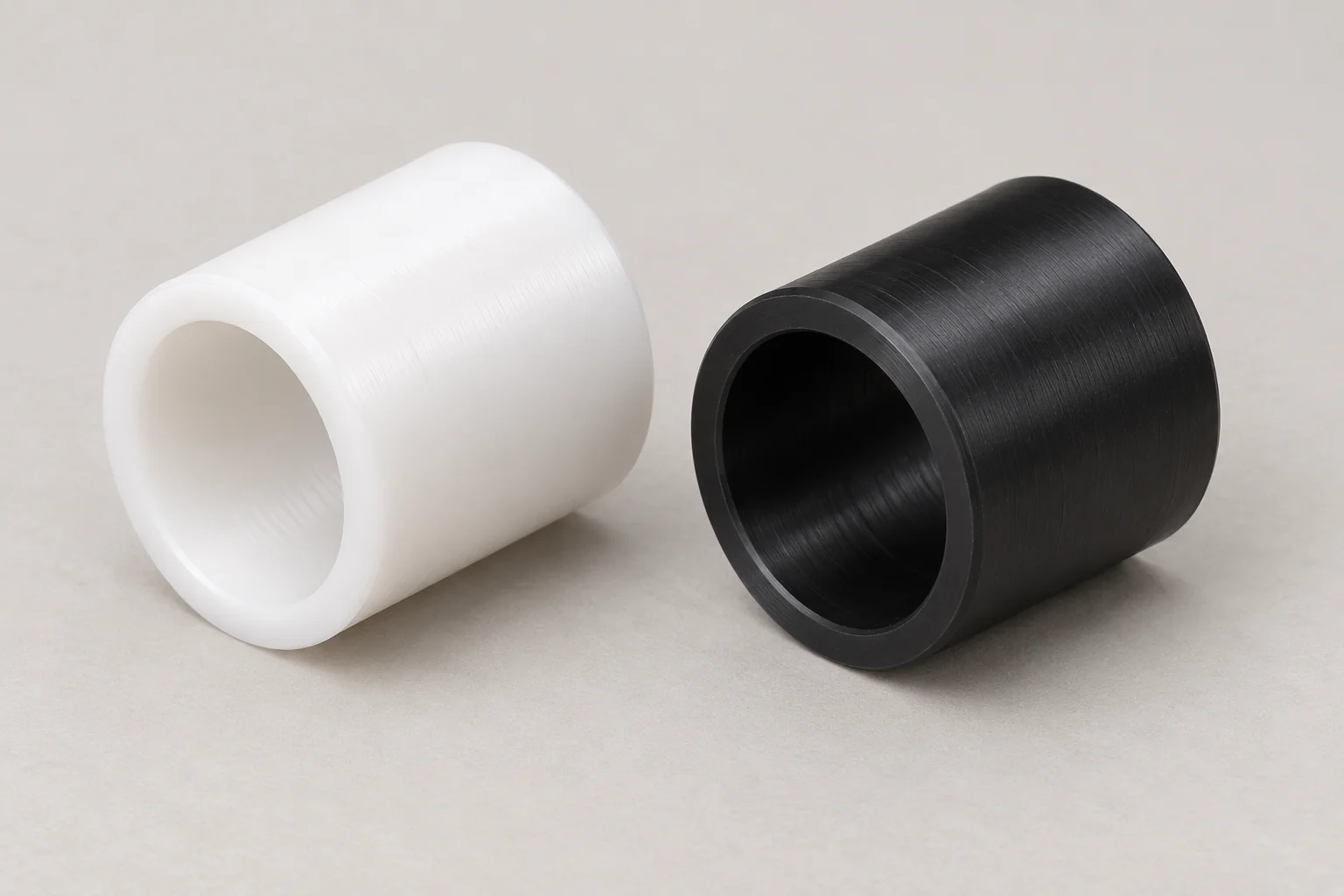
Plastic Sleeve Bushings
Straight cylindrical bushings for shaft guidance, sliding contact and mechanical support. Specify the installed bore and bearing length.
Discuss this bushing →
SLEEVE / FLANGED / PRECISION BUSHINGS
TOPS Plastics manufactures custom CNC machined plastic bushings for industrial machinery, automation, robotics, equipment manufacturing and OEM applications. We produce sleeve bushings, flanged bushings, precision bearing sleeves and special-design components from PEEK, Delrin/POM, Nylon, PTFE, UHMW and other engineering plastics according to customer drawings and specifications.
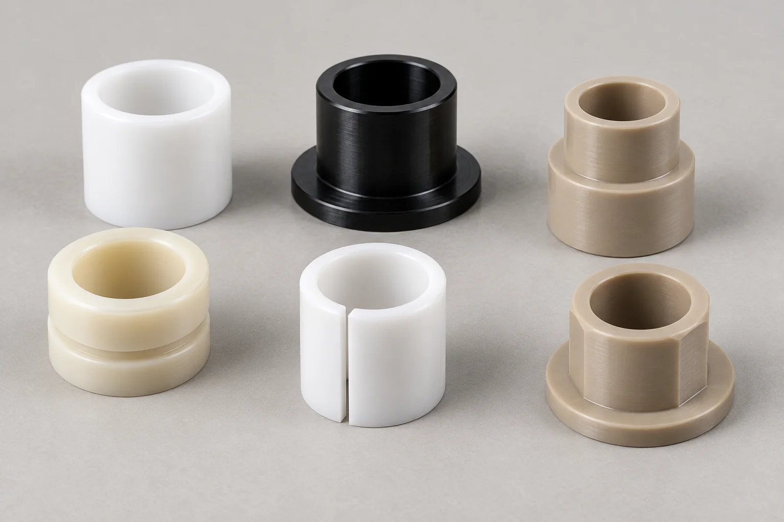
GEOMETRY FIRST
Choose the geometry that matches your assembly. Each design is made to your drawing, with the material, installed fit and functional surfaces reviewed together.
Straight cylindrical bushings for shaft guidance, sliding contact and mechanical support. Specify the installed bore and bearing length.
Discuss this bushing →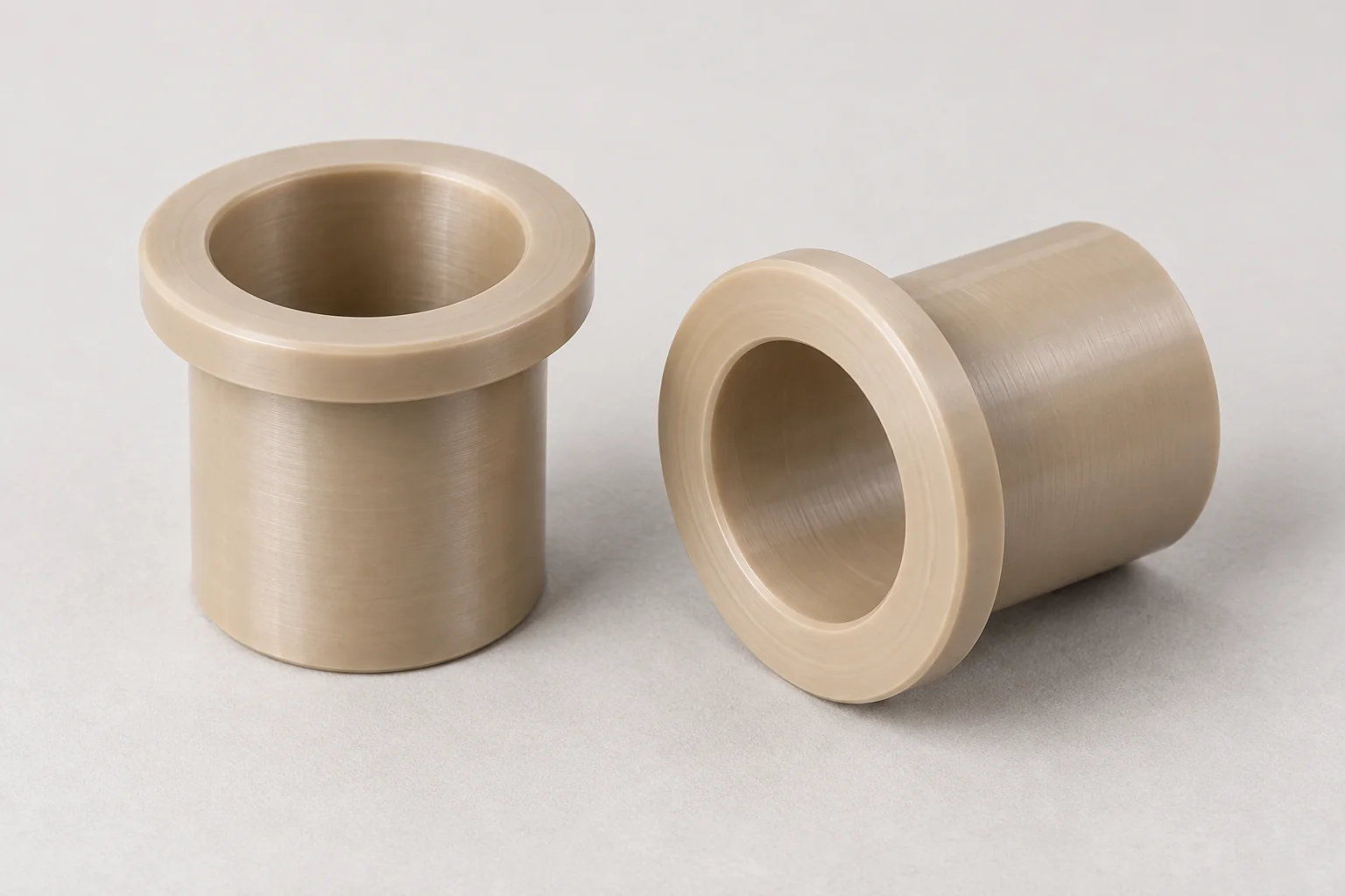
An integral flange provides axial positioning and, where the design allows, a thrust-bearing surface. Define both radial and axial loads.
Discuss this bushing →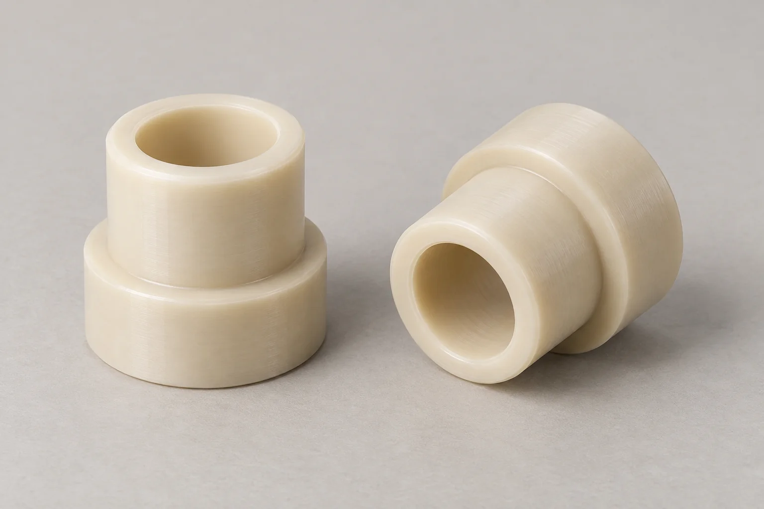
Multiple external diameters and shoulders locate the bushing within specialized housings or provide assembly stops.
Discuss this bushing →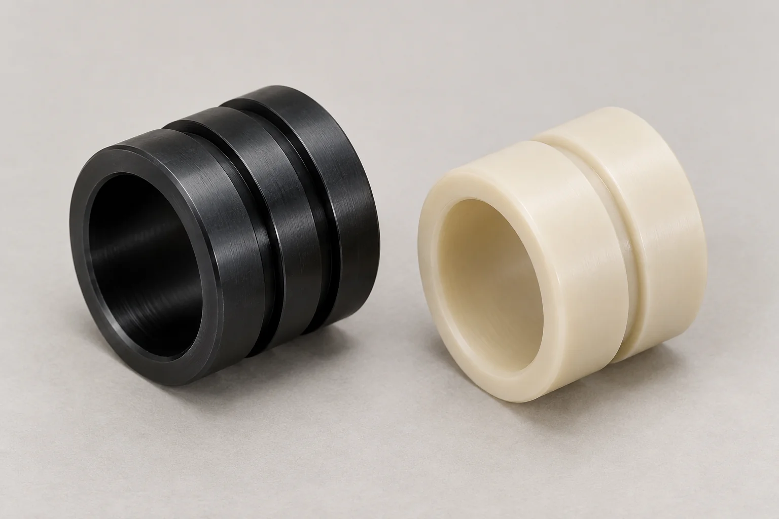
Drawing-specific grooves and slots support selected lubrication, location or retention requirements. Keep grooves clear of critical bearing contact where required.
Discuss this bushing →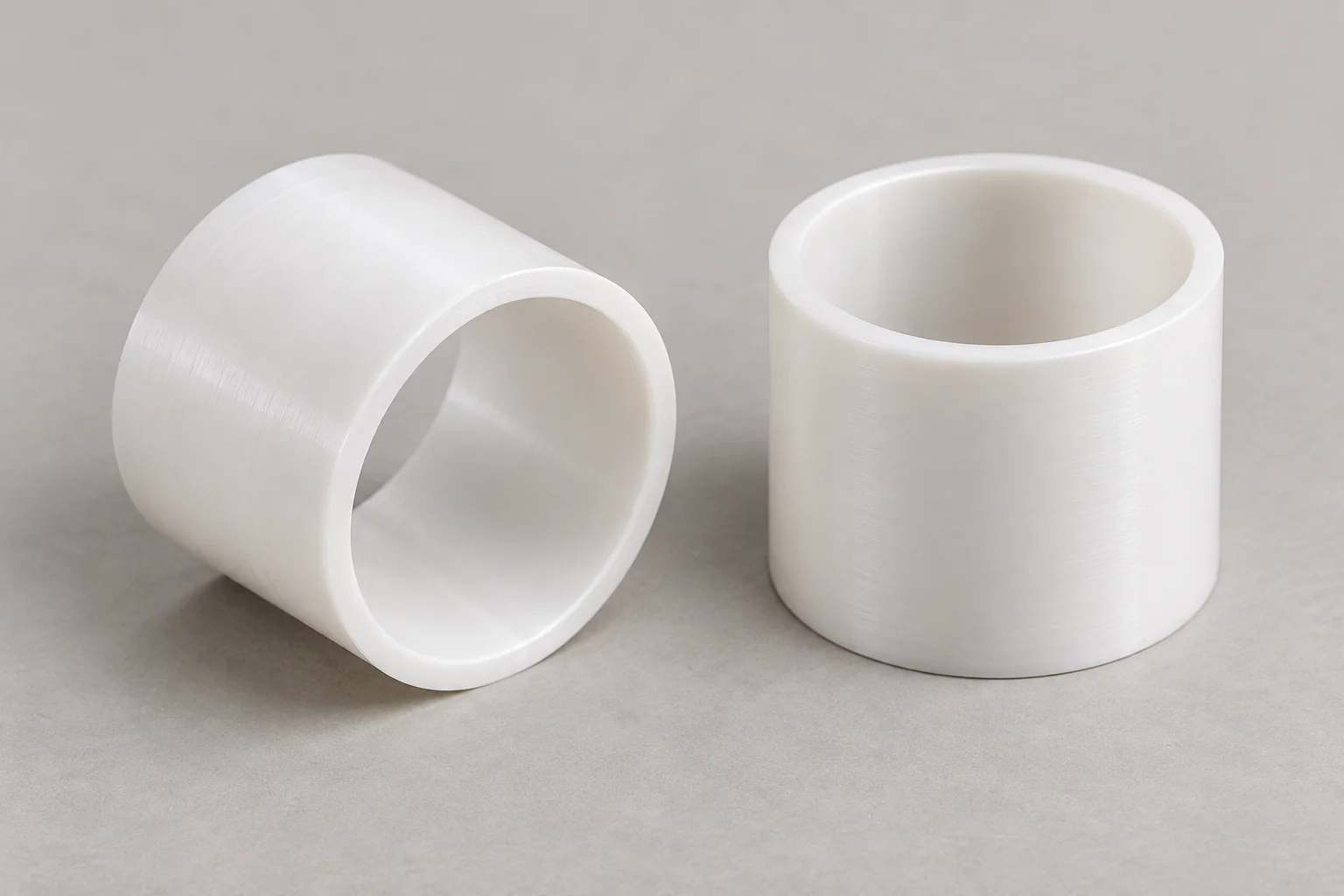
Space-saving sleeves require review of wall stiffness, clamping distortion and bore change during insertion.
Discuss this bushing →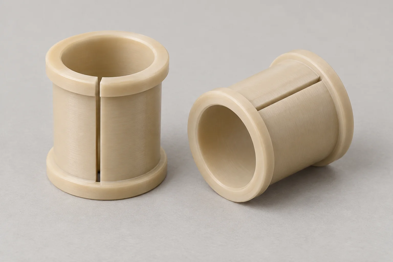
A longitudinal split can support particular installation and housing arrangements. Define the split gap and its condition after assembly.
Discuss this bushing →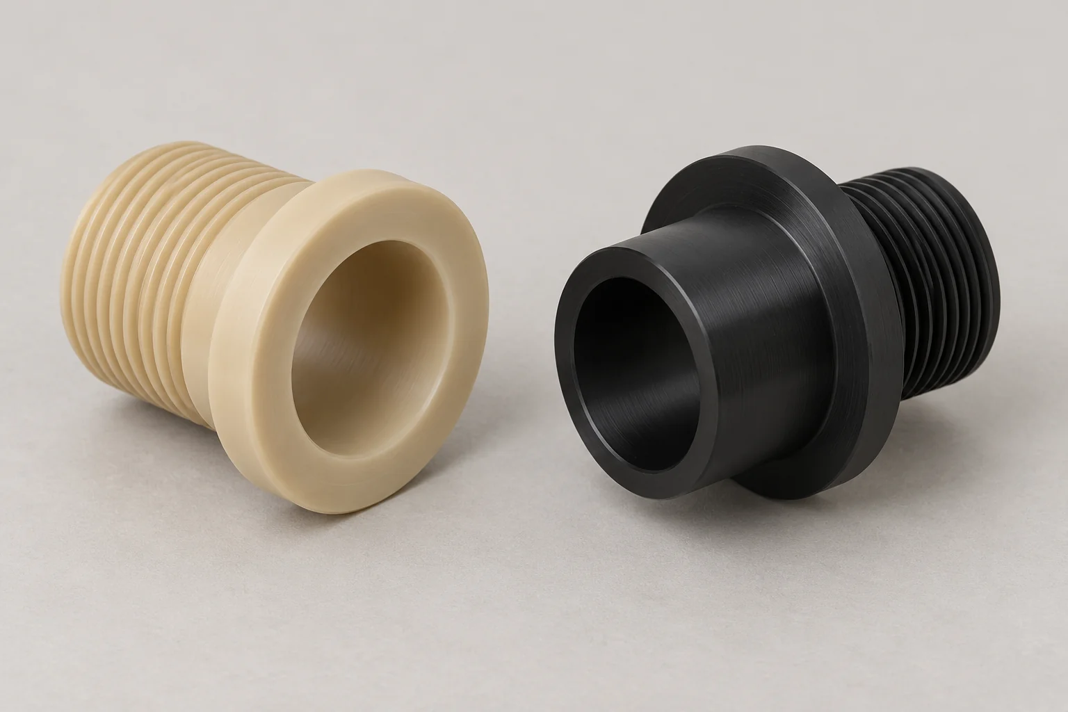
Specified threads provide mounting or location while the smooth bore guides the shaft. Review thread engagement and installation torque.
Discuss this bushing →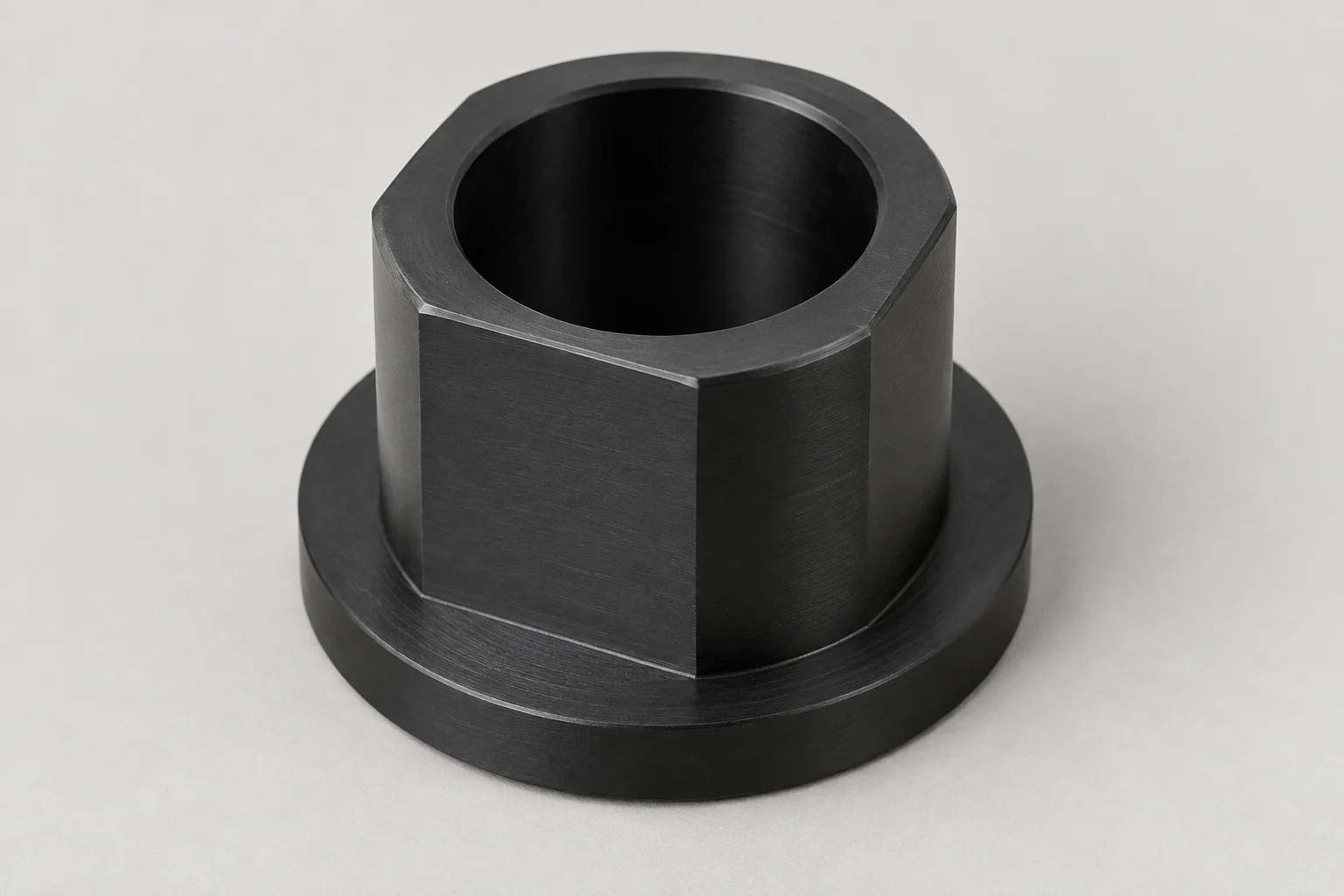
Nonstandard flanges, reliefs, chamfers, anti-rotation flats, eccentric bores and special profiles made to your drawing.
Discuss this bushing →01
Define the component and its mating parts together. Dimensions, grades, production quantities and inspection conditions are reviewed for each drawing.
| Specification | Customization options |
|---|---|
| Inner diameter (ID) | Custom shaft diameter and installed running fit |
| Outside diameter (OD) | Matched to the housing bore and retention method |
| Overall length | Drawing-specific bearing support and axial clearance |
| Flange diameter | Custom locating and thrust-face geometry |
| Flange thickness | Defined axial position and available assembly space |
| Wall thickness | Material, load and installation dependent |
| Features | Grooves, slots, chamfers, shoulders and reliefs |
| Materials | POM, Nylon, PTFE, PEEK, UHMW, PET-P and specified grades |
| Machining | CNC turning, boring and secondary milling |
| Production | Prototypes, small batches and repeat OEM orders |
| Inspection | Critical dimensions and specified functional fits |
02
Plastic bushings are cylindrical or specially shaped polymer components that support, guide, locate or separate machine elements. In sliding-bearing applications, a polymer surface sits between a shaft and housing to manage friction, wear and alignment without rolling elements.
The shaft slides or rotates against the bore while the bushing transfers radial load into the housing. Bearing length distributes that load; the installed bore and shaft diameter establish clearance. A flange may also locate the shaft assembly axially. Dry-running and maintenance requirements depend on the formulation and service conditions.
03
POM is often practical for precision mechanical bushings, nylon for tough wear applications, PTFE for low-friction or chemical environments, and PEEK for demanding thermal conditions. Select the exact grade against the shaft, load, speed, temperature, moisture and lubrication.
| Material | Main strengths | Selection considerations |
|---|---|---|
| Delrin / POM | Machinability, dimensional stability and low friction | A practical starting point for precision mechanical bushings; verify grade and chemical exposure. |
| Nylon / PA | Toughness and wear resistance | Moisture conditioning can change bore and fit; distinguish cast and extruded grades. |
| PTFE | Low friction and broad chemical resistance | Creep and low stiffness require support and load review. |
| PEEK | Strength at elevated temperature and chemical resistance | Higher cost; compare unfilled and bearing-grade compounds. |
| UHMW-PE | Abrasion and impact resistance | Lower rigidity and dimensional movement complicate close fits. |
| PET-P | Dimensional stability and low moisture absorption | Check grade, impact loading and temperature limits. |
| Filled bearing polymers | Tailored friction and wear behavior | Confirm filler type, shaft compatibility, supplier data and operating conditions. |
04
A bushing can match its drawing yet bind or wear quickly if the shaft, housing and installed bore are incompatible. Establish a working fit for the actual assembly condition.
Conceptual section, not to scale. The white gap represents running clearance; it does not prescribe an interference or clearance value.
Running clearance is the difference between the installed bushing ID and the shaft OD. Specify the acceptable range with both sets of diameter limits.
A press fit can reduce the bore. Interference, wall thickness, polymer stiffness and housing geometry influence the change; a generic interference value is insufficient.
Flange diameter and thickness control seating and axial location. Review the thrust surface, axial clearance and any shoulder radius on the mating part.
State whether dimensions apply to the loose bushing, a reference housing or the final assembly. Agree the housing size, support, temperature and conditioning used for inspection.
FIT REVIEW / DIMENSION LIMITS
Enter the minimum and maximum installed bushing ID and shaft OD in millimetres. The tool calculates a geometric clearance range from your inputs.
Calculated diametral clearance range
0.050 – 0.120 mmClearance throughout the entered range
Corresponding radial clearance range: 0.025 – 0.060 mm
Minimum diametral clearance = minimum installed ID − maximum shaft OD.
Maximum diametral clearance = maximum installed ID − minimum shaft OD.
Radial clearance is half the diametral clearance for a concentric assembly. Positive values indicate clearance; negative values indicate interference.
This tool does not calculate press-fit deformation or account for moisture, temperature, wear, loading or measurement uncertainty. Enter installed bore limits, not a free-state bore assumed to remain unchanged. The result is not a recommended running fit.
05
Load capacity and wear life depend on the complete sliding system. A material name alone does not establish a safe working load or a service-life prediction.
A simplified projected-pressure estimate is p = F / (d × L). With force F in newtons and effective bearing diameter d and length L in millimetres, p is in N/mm² (MPa). This average does not capture edge loading, misalignment or local stress.
Rotational and linear speed affect heat generation and wear. Include continuous speed, starts and stops, oscillation and duty cycle when requesting a review.
PV combines bearing pressure and sliding speed for preliminary material screening. Compare against data for the exact grade, temperature, lubrication and test conditions; it is not a universal acceptance limit.
Shaft hardness, roughness, coatings and condition influence wear and friction. A more highly polished shaft does not automatically improve every polymer pairing.
Dry running, lubrication, dust, moisture, chemicals and cleaning cycles can change performance. Only particular grades and conditions support dry-running service.
06
Capability depends on polymer grade, bore diameter, wall thickness, overall length, setup, conditioning and whether dimensions are checked before or after installation. We review critical fit requirements against the actual assembly condition.
| Critical feature | Main engineering consideration |
|---|---|
| Inner diameter | Shaft clearance and press-fit influence |
| Outer diameter | Housing interference or location fit |
| Concentricity / coaxiality | ID-to-OD axis relationship; define the required datum and control |
| Roundness | Bearing contact and distortion during clamping |
| Flange thickness | Axial positioning and thrust-face clearance |
| Face perpendicularity | Seating and alignment relative to the bore axis |
| Surface finish | Sliding behavior, wear and agreed measurement method |
| Thin-wall geometry | Cutting, clamping and insertion distortion |
| Overall length | Bearing support and axial assembly clearance |
07
Combine the bearing geometry with the locating and assembly features your equipment requires.
Define retention grooves, lubrication paths and split gaps in relation to the functional bearing area.
Locate the part axially and establish seating or thrust faces with clear datum relationships.
Add installation lead-ins and shoulder reliefs to prevent interference and edge damage.
Specify flats, mounting threads, eccentric bores or nonstandard outlines with their functional purpose.
08
Start with the mating assembly and operating conditions, then assign dimensions and controls to the features that determine function.
Review load, speed, temperature, chemical exposure, moisture and the mating shaft before selecting an exact grade.
State the acceptable installed clearance range. Nominal free-state ID does not define the working fit.
Thin walls can distort during machining and insertion. Review support and installation conditions early.
Bearing length affects projected pressure, alignment and sensitivity to shaft misalignment. Longer is not automatically better.
Lead-ins help installation and protect the bore. Specify which edges must remain sharp or carry a functional radius.
Conditioning and service temperature can shift dimensions. Establish relevant inspection and operating states.
Control the important bore, OD, face and datum relationships without applying unnecessary tight tolerances everywhere.
09
CNC turning and boring are the primary operations for rotational bushings. Secondary operations follow the functional details in your drawing.
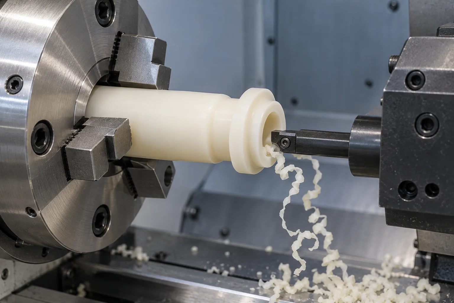
Machine the OD, ID, shoulders, grooves and flange faces with a setup chosen to control axis relationships and limit clamping deformation.
Add flats, slots, anti-rotation features and special profiles where the drawing requires them.
Control bore edges, remove loose material and inspect the functional surfaces. Avoid aggressive finishing that changes critical fits.
10
Plastic bushings suit applications that value low weight, corrosion resistance, lower noise or grade-specific dry running. Metal bushings may suit higher loads, greater stiffness or stronger heat dissipation.
| Factor | Plastic bushings | Metal bushings |
|---|---|---|
| Weight | Generally lighter | Generally heavier |
| Corrosion | Polymer-dependent; no metallic rust | Alloy and environment dependent |
| Lubrication | Some grades support dry running | Often needs lubrication or engineered bearing surfaces |
| Load capacity | Grade, temperature and duration dependent | Often stronger at high loads |
| Heat dissipation | Generally lower | Generally higher |
| Noise | May reduce operational noise | Depends on the bearing system |
| Chemical exposure | Certain grades resist selected chemicals well | Alloy dependent |
| Dimensional movement | Greater sensitivity to thermal movement and creep | Often more stable under sustained load |
11
Match the bushing function to the equipment interface. Material documentation and validation depend on the application; a polymer family name alone does not establish compliance.
Shaft guides, pivot bushings and sliding interfaces in mechanical equipment.
Positioning mechanisms, guide assemblies and repeated-motion pivots.
Roller interfaces, pivot points and moving machinery with defined wear and cleaning requirements.
Equipment bushings made from appropriately documented grades where food contact applies; confirm contact and cleaning conditions.
Instrument pivots and mechanical guides with application-specific material and cleaning requirements.
Sliding and pivot components exposed to impact, dirt, moisture and variable duty cycles.
Bushings and sleeves selected for the actual medium, concentration, temperature and exposure duration.
12
Agree the inspection state before production. For a press-fit design, check whether the functional bore must be measured in a specified reference housing rather than only in the free state.
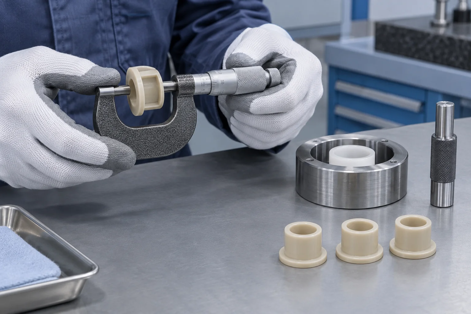
Material Grade Verification — confirm the specified polymer, filler and available documentation.
Drawing & Shaft-Fit Review — define mating shaft, housing bore, datums and inspection state.
First Article Machining — review the initial geometry and functional features against the agreed plan.
OD / ID / Length Inspection — use suitable equipment and support without deforming the part.
Roundness & Axis Relationship Checks — assess specified form and geometric relationships with an agreed method.
Bore / Edge / Surface Inspection — check burrs, chamfers, surface condition and bearing contact areas.
Final Documentation & Packaging — provide agreed records and protect the bore, edges and flange in shipment.
13
Use the prototype to establish the material and assembly fit, then carry approved requirements into repeat supply.
Evaluate shaft fit, material, geometry, installation and representative wear conditions before approving the design.
Make small batches for specialized OEM equipment without dedicated mold tooling. Confirm quantities and delivery needs for each RFQ.
Use controlled grades, approved drawing revisions and a repeatable machining and inspection plan.
14
A plastic bushing must do more than match its drawing. Material, final installed bore, shaft clearance, load and environment determine how it performs in service.
Build custom bushings around the dimensions, revision and functional requirements you supply.
Coordinate rotational bearing geometry with flats, grooves and other custom features.
Review suitable POM, Nylon, PTFE, PEEK, UHMW and other specified materials.
Discuss shaft and housing relationships before committing to a critical fit.
Support flanged, stepped, split and special-profile designs.
Develop the initial component and support recurring drawing-controlled batches.
Agree inspection equipment, conditions and documentation for the features that matter.
15
A clear sequence connects the engineering review with the approved part and repeat orders.
Share the drawing, CAD model, quantity and material preference.
Define shaft size, housing bore, running clearance, load and sliding speed.
Review the grade, machining approach, fit and inspection condition.
Confirm the quotation, drawing revision and agreed requirements.
Machine and inspect the first article or approved batch.
Review required records and pack functional surfaces for shipment.
Use feedback and approved revisions to control future orders.
Plastic bushings support, guide, locate or separate machine elements, often providing a sliding surface between a shaft and housing. Typical uses include pivots, shaft guides and mechanical sleeves.
Read the related guidance →A plastic bushing is a component geometry, usually a sleeve; a plastic bearing describes a load-supporting sliding or rotational function. A bushing used to support a moving shaft is a type of plain bearing.
Read the related guidance →The best material depends on load, speed, shaft material, temperature, moisture, chemicals and lubrication. POM, Nylon, PTFE, PEEK, UHMW and PET-P offer different balances; select the exact grade against the application.
Read the related guidance →Neither is universally better. Delrin/POM often suits stable precision fits, while Nylon offers toughness and wear resistance but needs moisture-related dimensional review. Compare grades under your service conditions.
Read the related guidance →Some PTFE grades can operate dry in suitable conditions, but PTFE does not guarantee maintenance-free performance. Check pressure, speed, creep, temperature and shaft compatibility for the chosen compound.
Read the related guidance →Diametral clearance equals installed bushing ID minus shaft OD. Minimum clearance uses minimum installed ID minus maximum shaft OD; maximum clearance uses maximum installed ID minus minimum shaft OD. Radial clearance is half the diametral value for a concentric assembly.
Read the related guidance →Achievable tolerances are reviewed for the exact grade, dimensions, wall thickness, setup and inspection state. Submit the drawing and installed fit requirements for a feature-specific review rather than relying on a universal tolerance.
Read the related guidance →Yes, where the material and design allow a suitable press fit. Interference can reduce the bore; review the housing, wall thickness, temperature, conditioning and installed clearance together.
Read the related guidance →A sleeve bushing has a straight cylindrical profile; a flanged bushing adds an integral rim for axial location and, in appropriate designs, thrust contact.
Read the related guidance →Yes. Send a drawing or CAD model with material preference, quantity and mating assembly requirements so TOPS Plastics can review the geometry, fit and machining approach before quotation.
Read the related guidance →THE BUSHING AND ITS MATING PARTS
Upload your bushing drawing or 3D CAD model and provide the material, quantity, critical dimensions, shaft and housing sizes, required running clearance and operating conditions. Our team can review the geometry, material suitability and CNC machining requirements before quotation.
Include bushing type, exact grade, ID, OD, length, flange dimensions, shaft material and diameter, housing bore, press-fit requirement, radial and axial load, speed, duty cycle, temperature, moisture or chemicals, lubrication and critical GD&T in the drawing or accompanying email. The form keeps project details optional; only company, name, email and phone are required.
info@tops-precision.comSTEP / STP / IGES / X_T / DWG / DXF / PDF or ZIP, maximum 10 MB. Larger packages can be shared by email. Agree confidential-file handling before sending sensitive drawings.