01
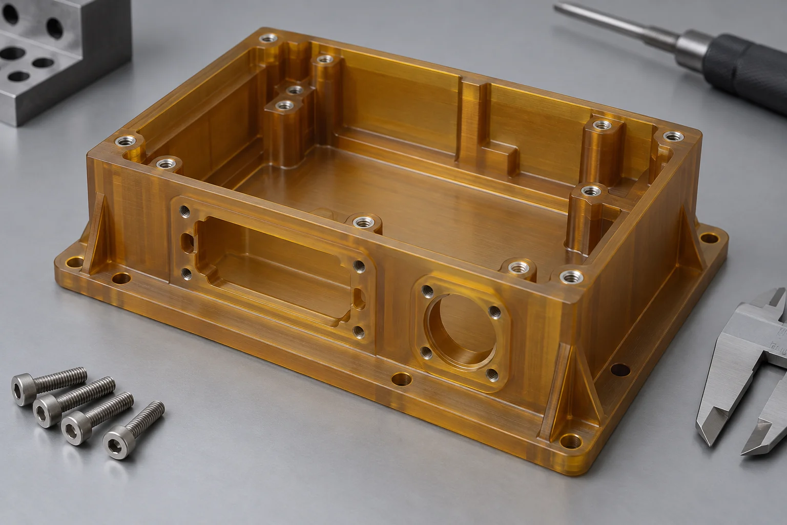
Plastic Housings
Bodies for avionics, sensors, instruments and electrical modules. Specify connector interfaces, mounting datums, cavity geometry and the thermal environment.
Explore component details →
HIGH-PERFORMANCE POLYMERS · AEROSPACE EQUIPMENT
TOPS Plastics manufactures custom CNC machined plastic components for aerospace systems, aircraft equipment, avionics, UAVs, test systems and precision mechanical assemblies. We machine PEEK, PEI/Ultem, PAI/Torlon, PPS, PTFE, POM and other engineering plastics according to customer drawings, material specifications and application requirements.
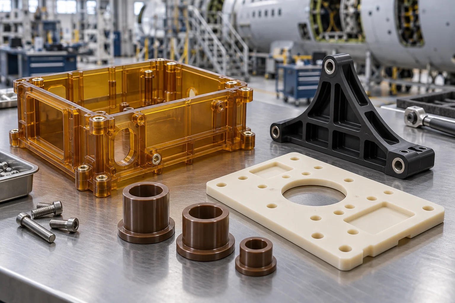
Review the part function, approved grade and project evidence requirements before selecting the machining and inspection route.
| Capability | TOPS Plastics |
|---|---|
| Typical parts | Housings, insulators, bushings, bearings, spacers and fixtures |
| Materials | PEEK, PEI, PAI, PPS, PTFE, POM and specified grades |
| Processes | CNC milling, turning, 5-axis machining, drilling and tapping |
| Key requirements | Weight, thermal stability, wear, insulation and documentation |
| Production | Prototype, low-volume and recurring production |
| Input | STEP, CAD, 2D drawings and reference samples |
| Inspection | Drawing-based dimensional inspection of agreed features |
| Documentation | Material and inspection documents where specified, agreed and available |
Explore parts by function, then define service loads, approved grade and the evidence required for the program.
Bodies for avionics, sensors, instruments and electrical modules. Specify connector interfaces, mounting datums, cavity geometry and the thermal environment.
Explore component details →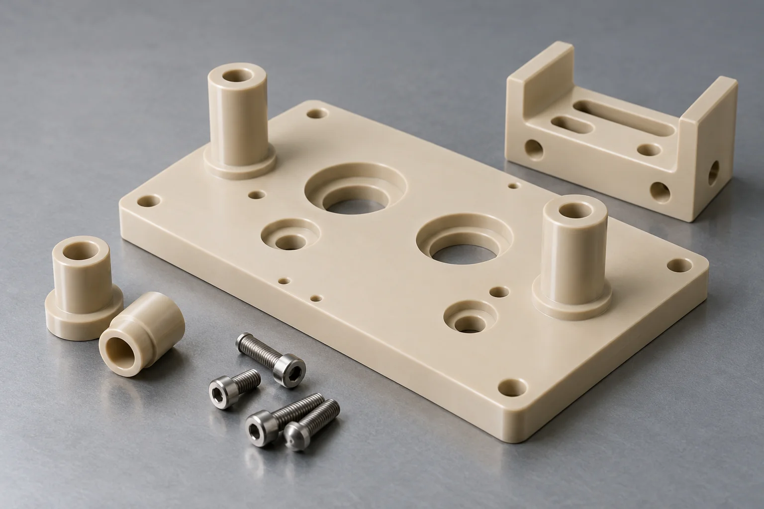
Electrical isolation, connector supports and higher-temperature equipment supports. Exact-grade dielectric and fire-performance requirements must be defined.
Explore component details →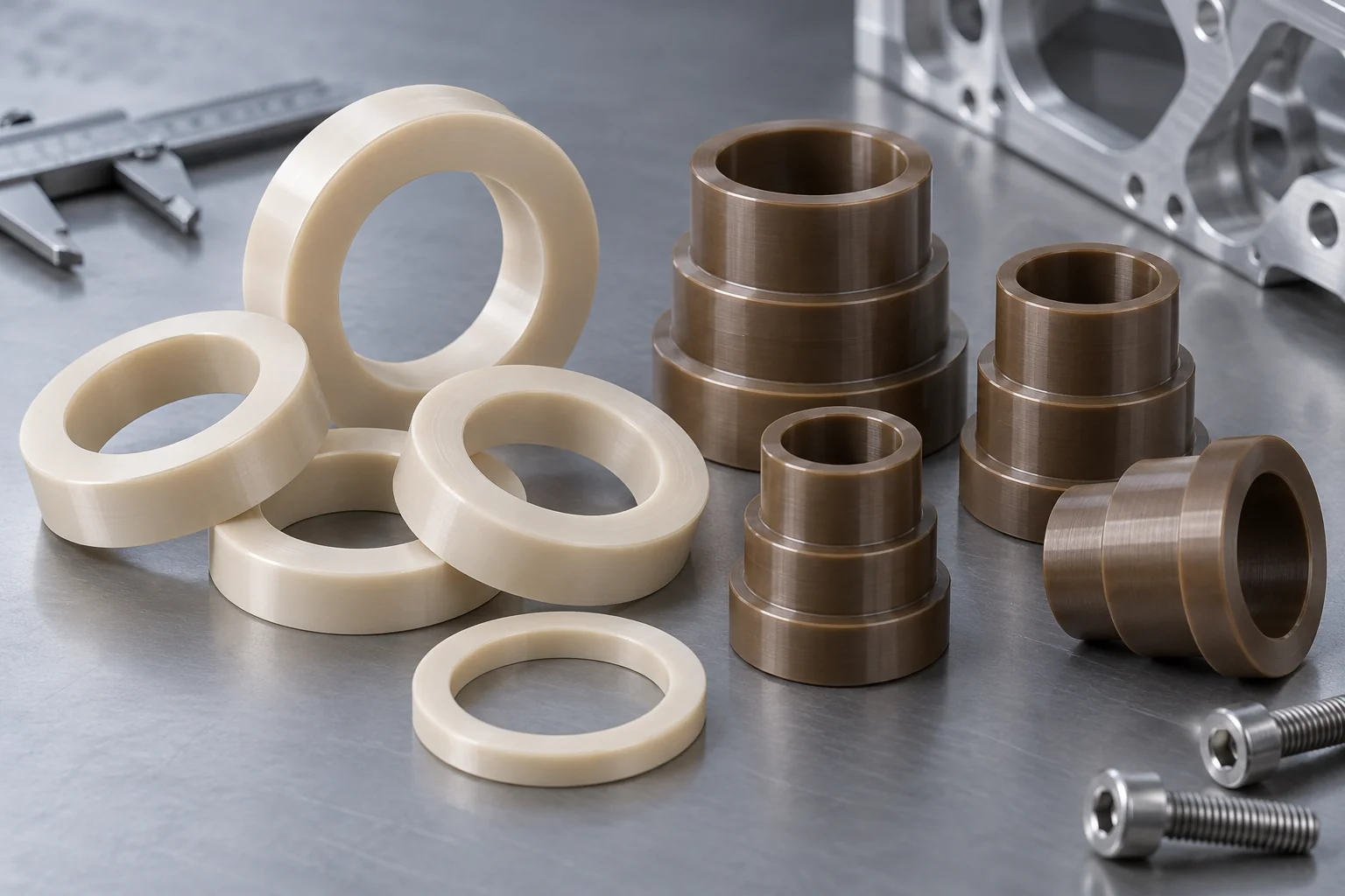
Controlled stack height, electrical separation and lightweight assembly interfaces. Specify thickness, parallelism, bore fit and retained load.
Explore component details →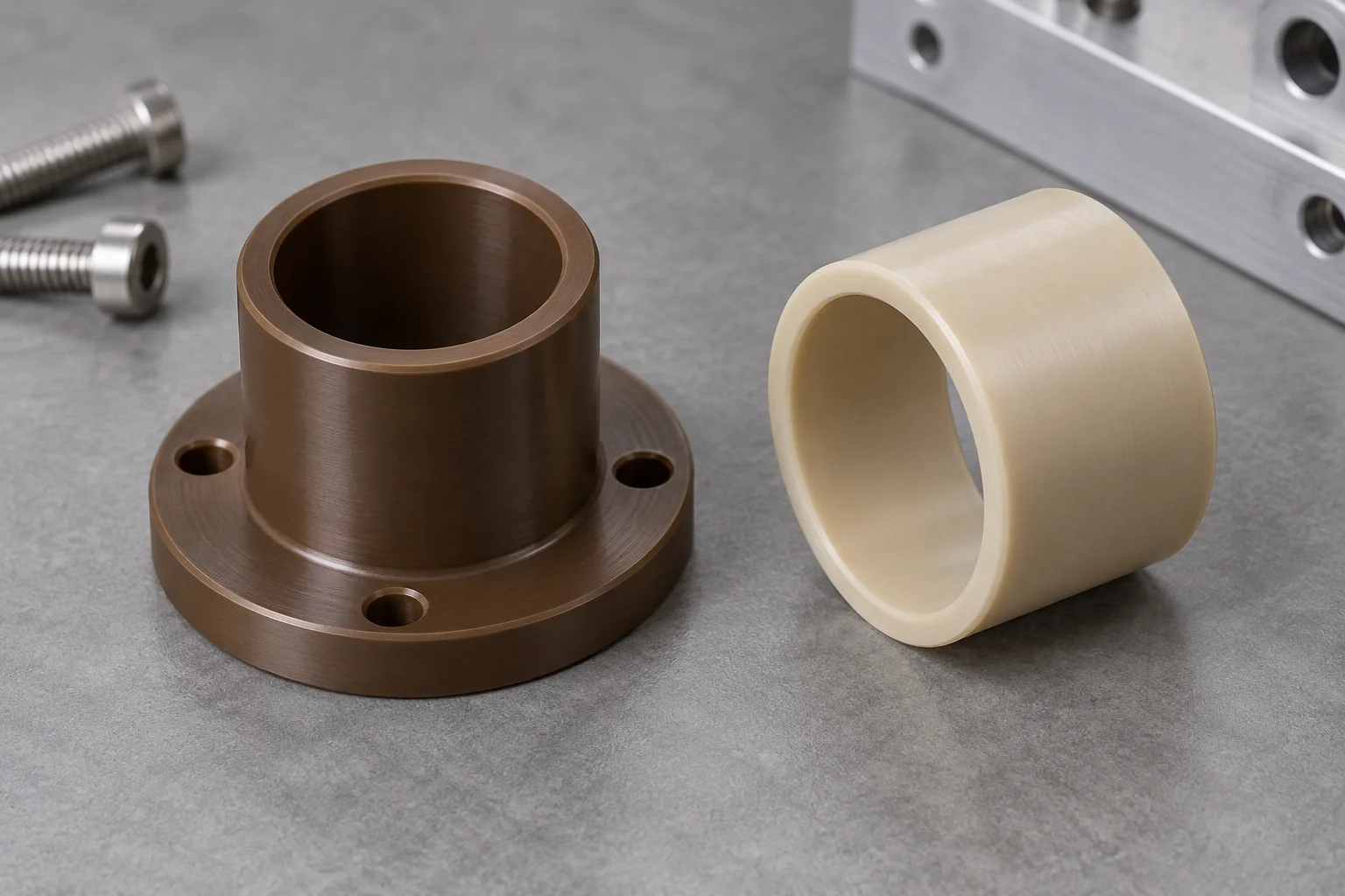
Plain bearings, pivots, actuation and sliding interfaces. Review load, speed, temperature, counterface, lubrication and wear together.
Explore component details →Plastic Bushings →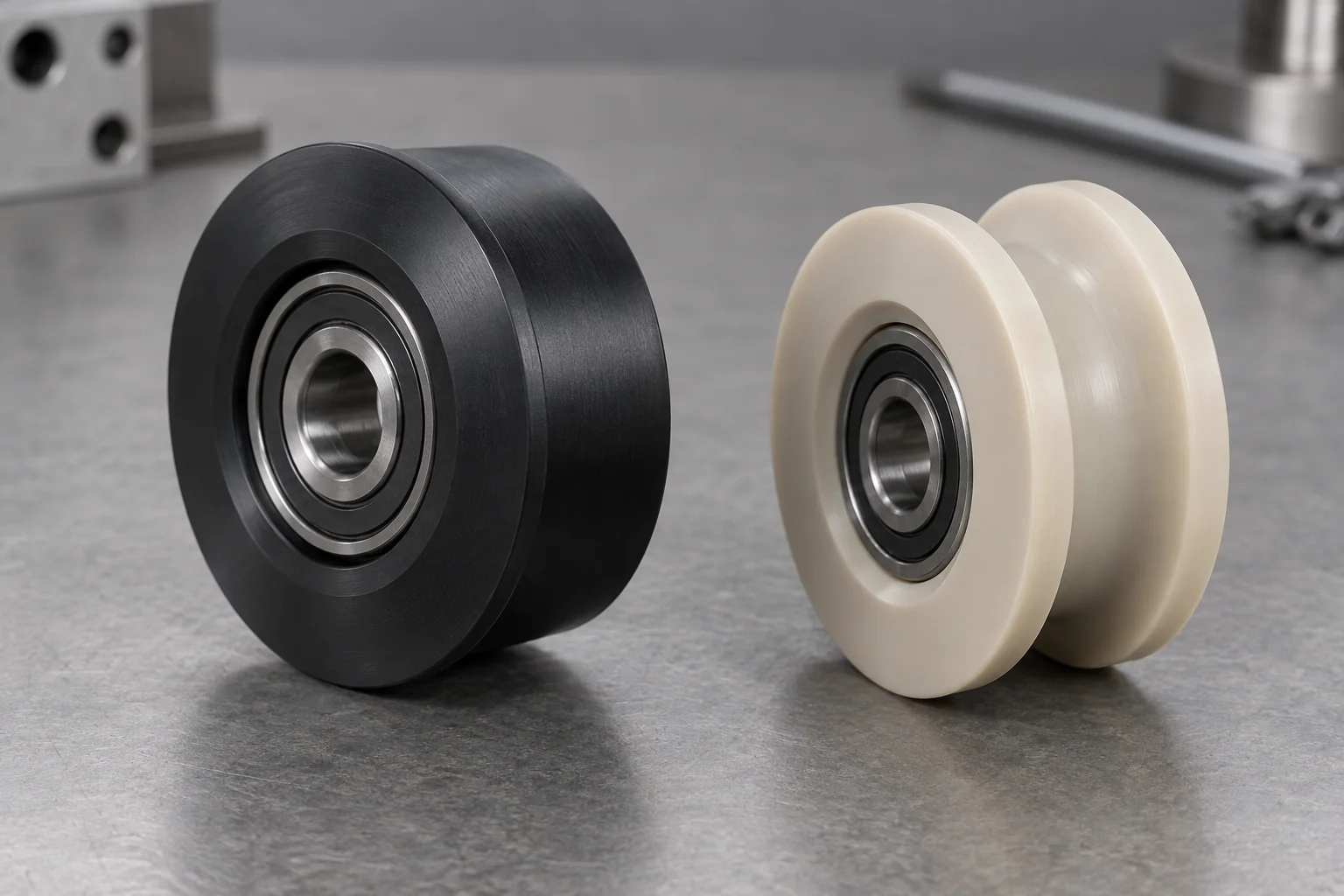
Guide rollers and motion components for equipment mechanisms. Define profile, bearing fit, contact load, clearance and operating cycle.
Explore component details →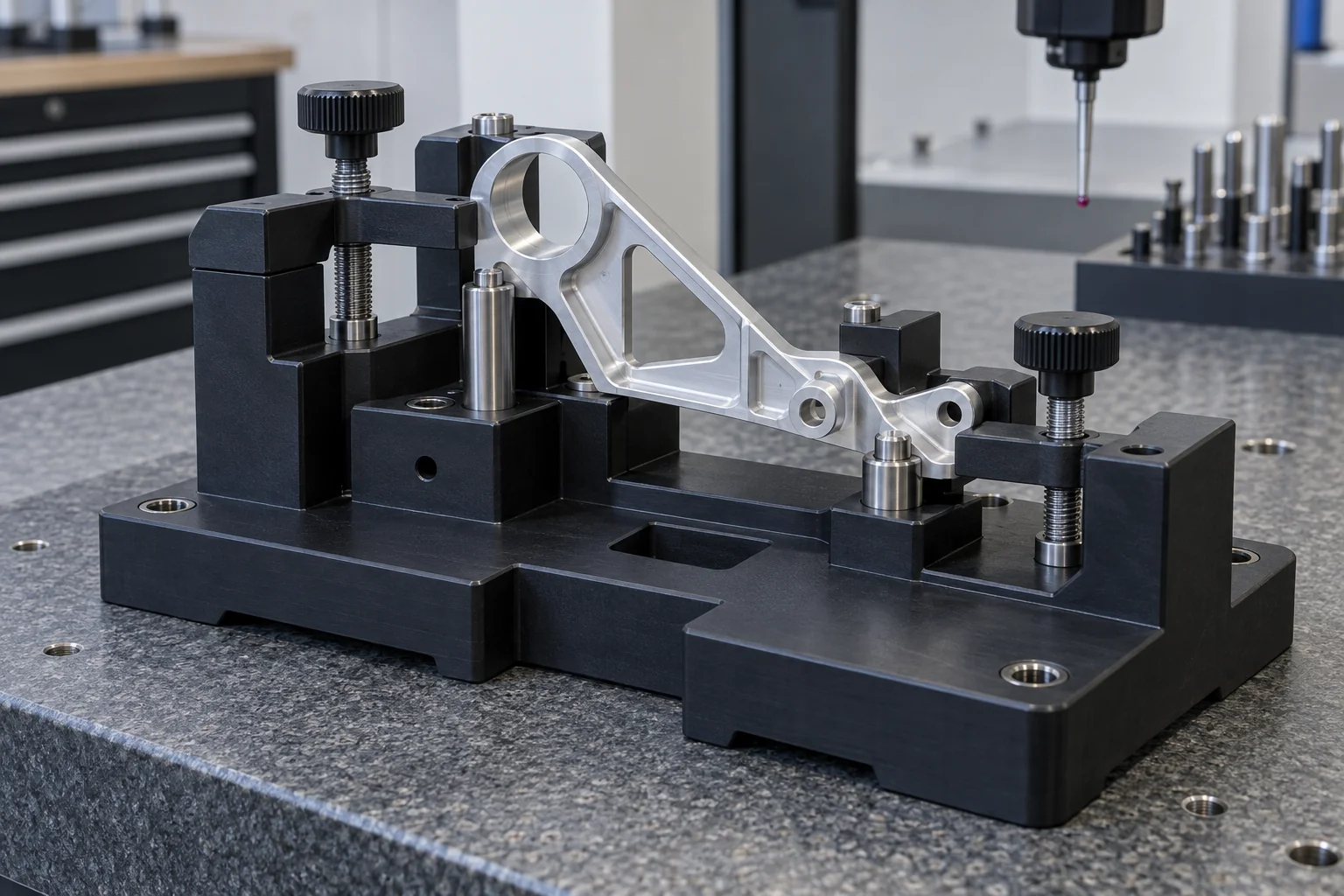
Assembly, inspection, component manufacturing and test tooling. Establish functional datums, part support, hardware and repeatability requirements.
Explore component details →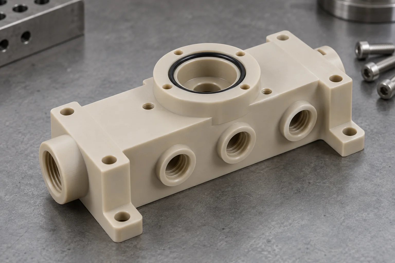
Fluid-routing, pneumatic and test-equipment blocks. Define actual media, pressure, port standards, seals and internal passage inspection.
Explore component details →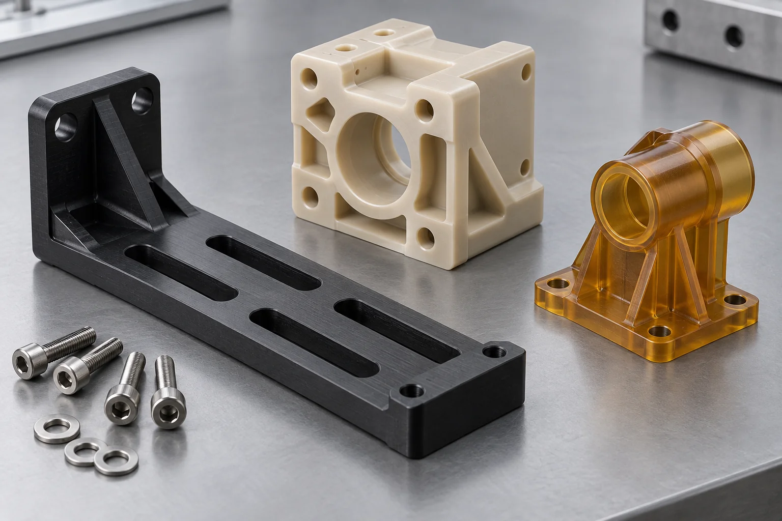
Nonstandard plates, guides, brackets and precision blocks built to released customer drawings and grade specifications.
Explore component details →Part function and service environment determine whether a polymer is appropriate. Distinguish installed aircraft components from manufacturing tooling, instrumentation and ground-support equipment.
Insulators, connector housings, spacers, sensor mounts and PCB supports. Review electrical isolation, dimensional stability, specified fire performance and mass.
Brackets, spacers, housings, covers and guides. Weight, appearance, service loads, cleaners and applicable fire-performance criteria need review.
Bushings, bearings, rollers, wear pads and guides. Friction, wear, load, temperature and dimensional stability affect service behavior.
Manifolds, valve bodies, guides and sealing interfaces. Media compatibility, pressure, temperature and seal design must be evaluated together.
Lightweight housings, brackets, spacers, sensor mounts and insulators. Check stiffness, impact, thermal movement and environmental exposure.
Fixtures, nests, gauges, insulators and support blocks. Define setup datums, functional loading and the required inspection evidence.
There is no single best aerospace plastic. Compare exact grades against load, temperature, friction, chemicals, electrical behavior and the applicable project specification.
| Material | Main advantage | Application direction | Review before selection |
|---|---|---|---|
| PEEK | Heat, strength, chemicals and wear | Demanding structural precision parts | Exact grade, fillers, load and service temperature |
| PEI / Ultem | Thermal and electrical performance | Avionics and selected interior technical parts | Applicable fire tests, thickness and formulation |
| PAI / Torlon | Strength, wear and thermal performance | Loaded bearings, bushings and precision parts | Conditioning, moisture and retained dimensions |
| PPS | Chemical and dimensional performance | Technical electrical / mechanical parts | Fillers, brittleness and operating conditions |
| PTFE | Low friction and broad chemical resistance | Sealing, sliding and isolation components | Creep, stiffness and grade-specific wear behavior |
| POM / Delrin | Precision machining and stability | Lower-temperature mechanical components | Temperature, chemical exposure and service limits |
| Polycarbonate | Impact resistance and transparency | Transparent equipment covers and guards | Cleaning exposure, stress cracking and required tests |
| Acrylic / PMMA | Optical clarity | Viewing and instrumentation components | Impact, solvent exposure and optical acceptance |
PEEK may suit demanding structural or thermal duties, PEI electrical interfaces with specified fire requirements, PAI loaded wear components, and PPS chemically compatible stable parts. These are selection directions, not blanket aerospace qualifications. Use the approved material specification and supplier data for the actual grade.
Connector housings, insulators, spacers, sensor mounts, PCB supports, terminal blocks and cable-routing parts combine electrical and mechanical duties.
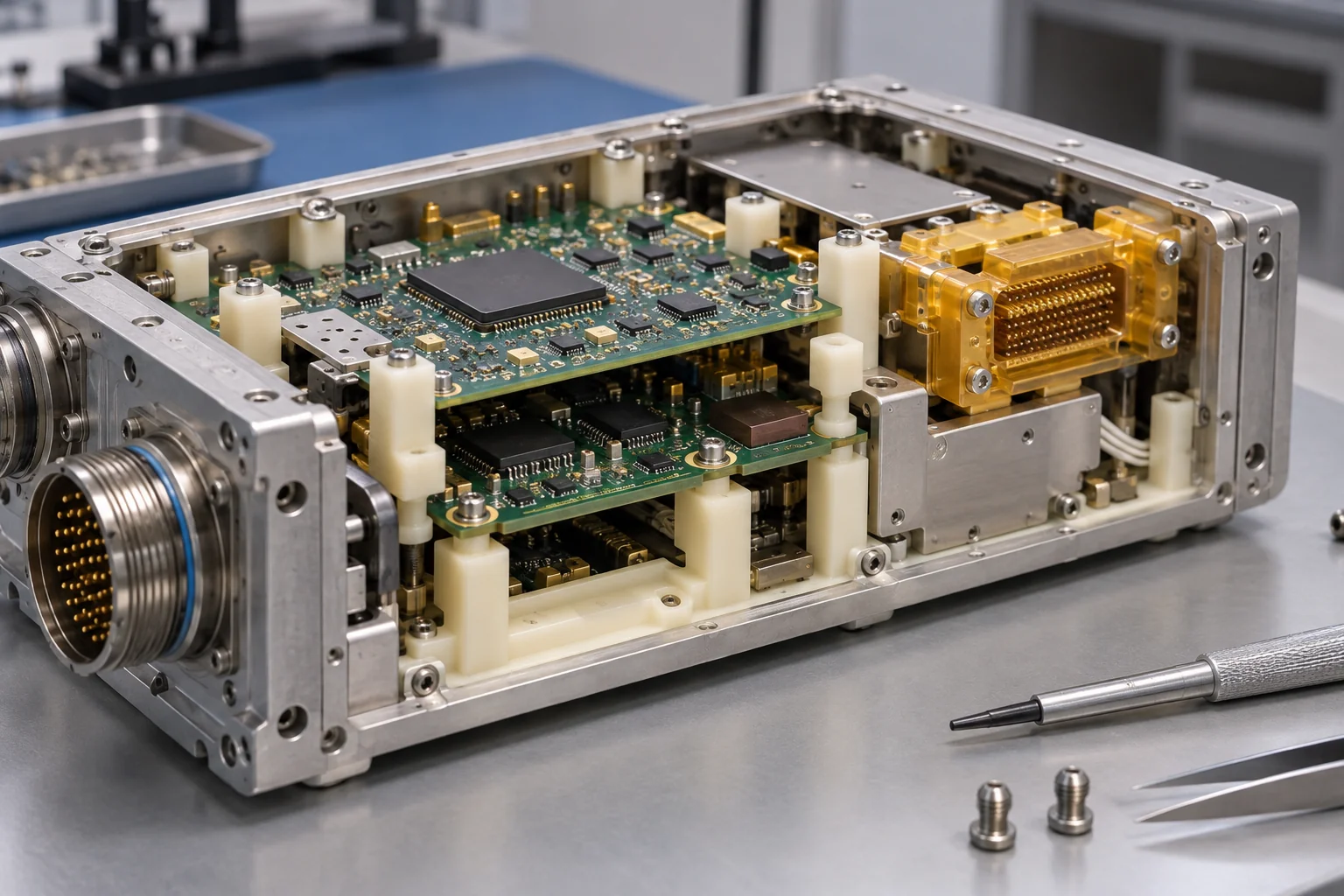
Specify dielectric performance, electrical resistance and applicable test conditions. Conductive or filled grades can behave differently from insulating grades.
Define required geometry and separation distances in the equipment design. Machining inspection verifies agreed features; system electrical validation is a separate scope.
Provide continuous and peak temperatures and the exact fire-test specification. A generic high-temperature label is not sufficient.
Control mounting datums, connector openings and supports through temperature and assembly loading. Include mating-part data where it defines fit.
The exact resin grade matters as much as the polymer family. Electrical, thermal and fire-related data can vary with formulation, colorants, reinforcement and thickness. Review the complete assembly, including metal inserts and fasteners.
Potential brackets, supports, covers, spacers, housings, trim-support structures and fixtures require review against their location and aircraft program specification.
Identify the applicable flame, heat-release, smoke or toxicity requirement and required evidence. The relevant test set depends on the application and program.
Material requirements may depend on resin grade, thickness, finish, coating and test specimen configuration. A family name or unrelated rating does not qualify a part.
Define cosmetic limits, repeated handling loads, attachment geometry and maintenance access. Avoid stress concentrations near mounting points.
Include cleaning chemicals, temperature and repeated service exposures. Confirm compatibility with the specified formulation.
Where 14 CFR 25.853 applies, the customer must identify the applicable test criteria and component scope. Do not treat a general flame-retardant material description as proof of compliance. Customer-specified fire-performance and documentation requirements can be reviewed during quotation.
Bushings, plain bearings, wear pads, rollers, guides and thrust components should be selected around operating duty rather than material name alone.
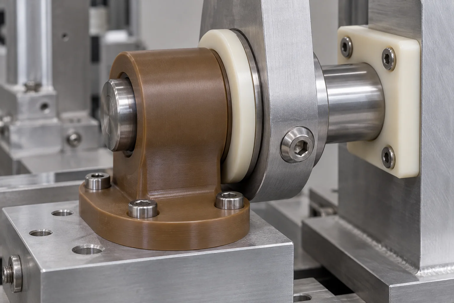
Provide radial or axial load, speed, travel, duty cycle and starting or peak conditions. Contact area and support geometry affect local stress.
Specify mating material, finish, hardness and alignment. Friction and wear data must be relevant to the actual interface.
Include heat generated by motion, ambient limits and dry or lubricated operation. Lubricant compatibility and retained clearance require review.
PAI, PEEK, PTFE-based grades or POM may be candidates for different duties. Define wear acceptance, replacement limits and inspection access.
Motion parts need load, speed, temperature, friction, wear, counterface and lubrication reviewed together. A filled wear grade may change stiffness, electrical behavior or counterface wear; evaluate those effects before substituting it for an unfilled material.
Manifolds, valve blocks, housings, spacers and fitting interfaces can be reviewed for specified equipment and fluid-handling applications.
Identify the exact liquid or gas, concentration, additives and cleaning agents. Review the grade at the actual temperature and exposure duration.
Provide continuous and peak conditions, cycling and mechanical restraint. Pressure capability is part-specific and requires defined validation.
Specify port standards, thread type, O-ring geometry, mating fittings and surface requirements. Include assembly loads or torque limits where relevant.
PEEK, PTFE, PPS or PVDF may be candidates in selected equipment. Chemical resistance alone does not establish sealing, stiffness or long-term pressure performance.
Agree any leak, flow or pressure testing separately from dimensional inspection. Provide internal passage geometry and access requirements so burr removal, cleaning and inspection can be considered before manufacture.
Sensor housings, electronics supports, spacers, brackets, cable guides and insulating blocks can support compact equipment layouts and rapid design iteration.
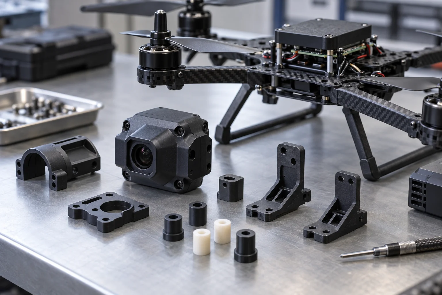
Engineering plastics can reduce component mass, but section thickness and support must provide the required stiffness. Compare the full assembly rather than density alone.
Polymers can simplify electrical isolation. RF behavior is grade-, thickness- and frequency-dependent; fillers and coatings require review.
Specify UV, outdoor exposure, moisture, vibration, shock and temperature cycling. Protective coatings or seals can alter the material and interface requirements.
Use machining for drawing-based revisions, fit checks and low-volume equipment builds. Capture the approved grade and critical interfaces before repeat supply.
Check thermal expansion and structural loading against surrounding metal or composite structures. A lighter replacement is useful only if alignment, retention and required service performance are preserved.
Selection should follow the actual temperature range and applicable fire-performance specification rather than generic high-temperature or flame-resistant descriptions.
Provide continuous, peak and transient temperatures with load and exposure duration. Retained strength and creep can matter more than a single published temperature value.
Tie required behavior to the exact grade, thickness, finish and specified test. Different tests and ratings are not automatically interchangeable.
Where required for selected interior or transport applications, identify the test method and program acceptance criteria. Confirm evidence availability before ordering material.
Plastic-to-metal assemblies need allowance for differential movement. Review clearances, mounting constraints and datum stability across the service range.
Material supplier test data is a starting point. The customer must determine whether it covers the component configuration and applicable program requirement. Any additional testing or certification scope needs explicit agreement.
Accuracy must be maintained in materials sensitive to temperature, clamping force, residual stress and reinforcement. Machining strategy and inspection should suit the actual grade.
Part size and close fits can change with temperature. Define inspection conditions and the intended service fit.
Clamping, cutting and assembly loads may distort housings or lightweight sections. Review support and measurement force.
Stock removal can release residual stress. Consider stock condition, geometry and a machining sequence that limits movement.
Pins, bearings and inserts can distort a bore or housing. Specify assembled fit and retention requirements.
Tool reach, heat and chip removal affect finish and dimensional control. Review access and internal radii early.
Reinforcement can change cutting behavior and directional properties. Record material orientation where it matters to fit or performance.
For spacecraft-related equipment, vacuum test systems, optics and instrumentation, review the exact grade, fillers, conditioning state, temperature and customer outgassing specification.
Where specified, identify total mass loss and collected volatile condensable material criteria, test method and acceptance limits. ASTM E595 data must match the relevant material and conditions.
State operating pressure, duration and sensitive nearby surfaces. A screening result does not automatically establish suitability for every optical or vacuum system.
Define thermal cycles, conditioning and proposed bakeout requirements. Review effects on geometry, material properties and assembled components.
Provide the required grade evidence and any component-level test scope. Supplier data and database entries should be checked for formulation, processing and test relevance.
Polymer family alone does not establish vacuum suitability. Customer qualification determines whether available evidence is sufficient for the intended application; additional outgassing testing is not implied by a standard machining quotation.
Assembly-critical interfaces and functional surfaces often matter more than appearance on nonfunctional areas. Define both clearly on the drawing.
Control bore condition, edge quality and contact finish to support the intended fit and movement. Avoid loose burrs or chips.
Specify sealing lands, grooves, passage intersections and port edges. Plan inspection and cleaning access for internal geometry.
Check hole patterns, mating faces and openings against datums. Deburring must preserve functional lands and retention details.
State permitted scratches, tool marks and edge breaks where appearance matters. Protect finished interfaces during handling and shipment.
Identify the dimensions controlling fit, alignment, sealing, motion and load transfer. Agree feature-specific limits after grade and geometry review.
| Feature | Why it matters |
|---|---|
| Bore diameter | Bearing or shaft fit |
| Hole position | Assembly alignment |
| Flatness | Mounting or sealing contact |
| Parallelism | Structural alignment |
| Spacer thickness | Stack height and clearance |
| Housing interface | Electronics and sensor fit |
| Bearing seat | Motion and retention |
| Manifold port position | Fluid-system integration |
| Datum relationship | Multi-part assembly and inspection |
There is no universal aerospace plastic tolerance. Grade, size, thin sections, support, temperature and measurement force affect feasibility. Include GD&T, critical datums and the free or restrained measurement state where relevant.
Customer-specified material, inspection, traceability and documentation requirements can be reviewed during quotation. Confirm the required scope and evidence before production.

Request exact-grade supplier certificates or material documents where specified and available. State any approved supplier or material specification restrictions.
Define first-article samples, report format and the required standard or customer procedure. Confirm the agreed FAI scope before manufacture.
Identify reportable features, datums, sampling and inspection conditions. Special tests require separate agreement.
Use released CAD and drawing revisions consistently across purchasing, machining and inspection; review substitutions and changes before repeat supply.
State material-to-part identification, labeling, documentation retention and traceability requirements so support can be confirmed.
Agree any added checks, witness requirements, packaging protection or record packages that the program requires.
Manufacturing and dimensional inspection support a defined component scope. Program approval, qualification and installation acceptance remain subject to customer requirements. Provide the applicable specifications early so feasibility and evidence limits can be resolved before an order.
Progress from development geometry to controlled recurring supply using approved grades, released revisions and agreed acceptance requirements.
Validate geometry, mating fit, material direction and intended function. Distinguish a fit-check part from a qualification test article.
Refine tolerance priorities, support, material choice and interface details using representative loads and environment.
Support specialized equipment, UAV and subsystem builds with released CAD, material specifications and agreed inspection.
Maintain the approved grade, drawing revision, CNC program, inspection plan and documentation requirements under agreed order controls.
Review the complete service environment before production: temperature, fire requirements, load, wear, chemicals, electrical behavior, vacuum exposure, stability and documentation.
Review PEEK, PEI, PAI, PPS, PTFE and other engineering polymers for the specified function.
Machine complex pockets, bores, interfaces and multi-face components to customer drawings.
Connect housings, bearings, insulators, spacers, fixtures and manifolds to an appropriate manufacturing route.
Consider thermal expansion, wall thickness, support, stress and inspection conditions before machining.
Support development programs and recurring OEM equipment needs with released specifications.
Agree critical-feature checks, evidence and documentation for the order.
Move from application requirements to the detailed product page for geometry, interfaces and drawing preparation.
Direct answers about high-performance polymers, avionics, lightweighting, vacuum criteria, tolerances and documentation.
PEEK, PEI, PAI, PPS, PTFE and POM are common candidates for different equipment functions. Select the approved grade for load, temperature, electrical behavior, chemicals and required evidence.
PEEK combines useful mechanical, thermal, chemical and wear performance for demanding parts. The actual grade and component must still be reviewed against the application and program requirements.
Suitable PEI grades may be considered for electrical and thermal interfaces or selected fire-performance requirements. Match the documentation to the exact grade, thickness and applicable test.
PAI / Torlon may be considered for loaded bearings, bushings and precision wear components. Conditioning, moisture, temperature and the mating surface affect suitability.
Sometimes, after a full design review. Polymers can reduce mass and provide isolation or corrosion resistance, but stiffness, structural load and temperature may favor metal or hybrid construction.
Documented insulating grades of PEEK, PEI, PPS and other polymers may be candidates. Specify electrical requirements, temperature, fire criteria and the complete assembly configuration.
Some grades may be considered after reviewing the vacuum level, temperature, conditioning and required outgassing evidence. Polymer name alone is insufficient.
Realistic limits depend on grade, geometry, support and inspection conditions. Identify fit, alignment, sealing and motion-critical features for a drawing-specific review.
Yes, prototype and low-volume equipment components can be reviewed alongside recurring OEM supply. Provide approved material, released drawings, quantities and acceptance requirements.
Provide the drawing, exact grade, applicable material and fire specifications, inspection scope, FAI needs and traceability requirements. Include temperature, loads, exposure and any vacuum criteria.
APPROVED GRADE. SERVICE LOAD. PROJECT REQUIREMENTS.
Upload your aerospace component drawing or CAD model and specify the exact material grade, quantity, application, operating temperature, mechanical load, electrical or flame requirements, environmental exposure, critical tolerances and documentation needs. TOPS Plastics can review the part geometry and machining feasibility before quotation.
Company, name, email and phone are required. Country, part number, quantity and drawing upload are optional. Include technical requirements in the drawing or email; combine CAD and supporting files into one ZIP if useful.
info@tops-precision.comSTEP / STP / IGES / X_T / DWG / DXF / PDF or ZIP, maximum 10 MB. Larger packages can be shared by email. Agree confidential-file handling before sending sensitive drawings.