01
Plastic Guide Rollers
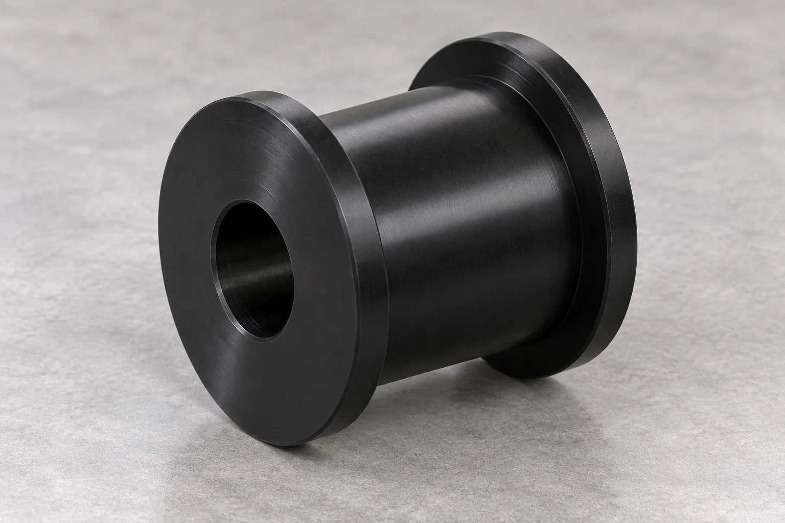
Guide belts, rails, products or moving components. Review groove profile, side load, bore or bearing arrangement and alignment.
Discuss this roller →
BUILT AROUND YOUR ROTATING ASSEMBLY
TOPS Plastics manufactures custom plastic rollers for automation, conveyor systems, packaging machinery, material handling, industrial equipment and OEM applications. We machine guide rollers, conveyor rollers, grooved rollers, bearing rollers and special-profile rollers from Nylon, UHMW-PE, POM/Delrin, PEEK and other engineering plastics according to customer drawings and operating requirements.
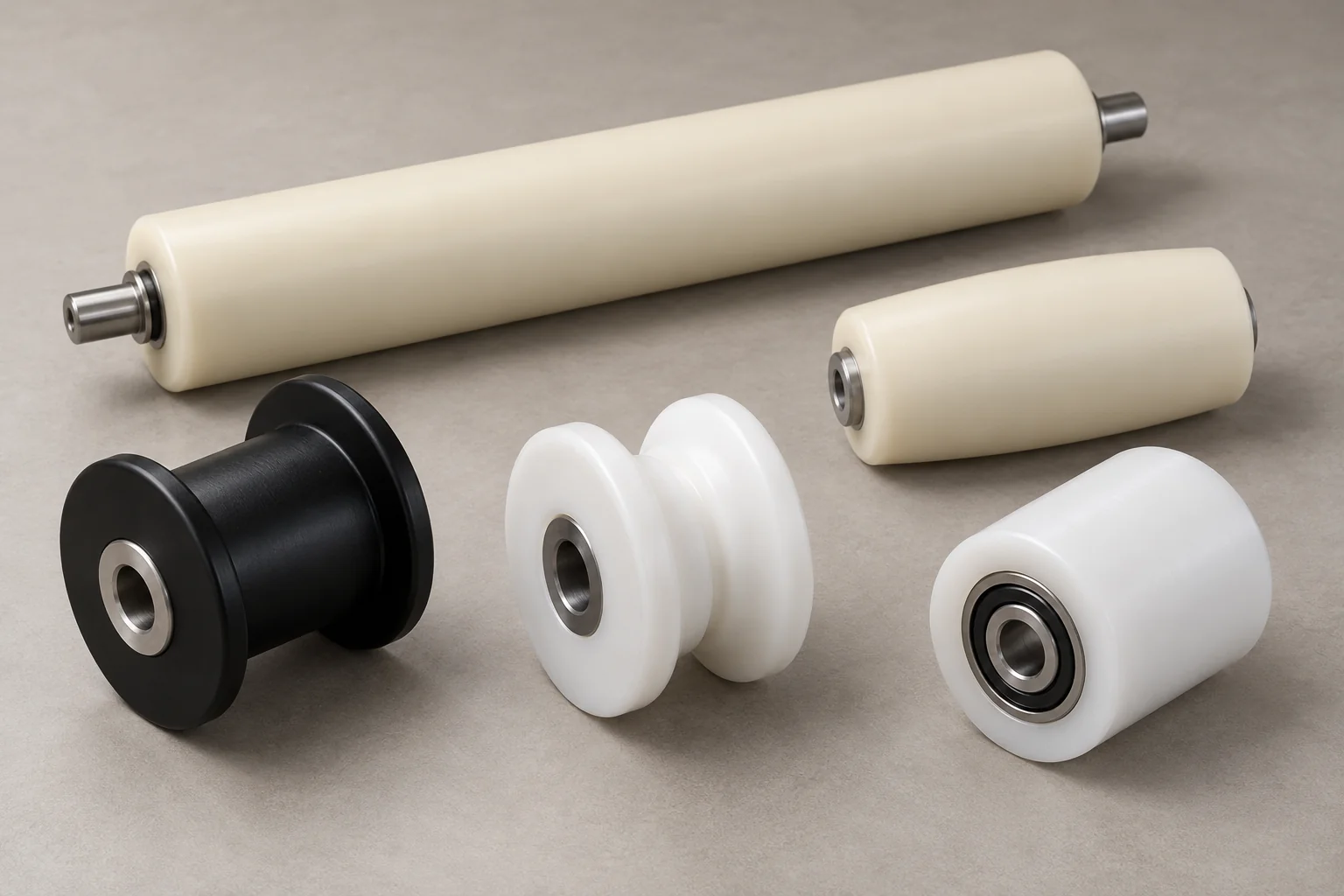
Custom-to-print rollers begin with the complete rotating assembly: contact diameter, face width, support arrangement and operating duty.
| Capability | TOPS Plastics |
|---|---|
| Roller types | Guide, conveyor, idler, drive, grooved, crowned and special-profile rollers. |
| Materials | Nylon, UHMW-PE, POM / Delrin, PEEK, HDPE, PET-P, PPS and specified engineering grades. |
| Geometry | Custom outer diameter, face width, bore, hub, flanges, steps and grooves. |
| Bearing options | Plain bore, machined bearing seat or inserted bearing where specified and agreed. |
| Shaft options | Through shaft, stub shaft and custom shaft interfaces reviewed with the assembly. |
| Processes | CNC turning, precision boring, secondary milling and drilling. |
| Production | Prototype, low-volume and repeat OEM production. |
| Input | 2D drawings, CAD models and reference samples. A worn sample requires a dimensional review. |
| Inspection | OD, bore, width, bearing-seat geometry, groove position and functional runout to the agreed drawing. |
Explore the roller geometry that matches your machine. Each component is reviewed against its shaft, bearings, product contact and duty.
Guide belts, rails, products or moving components. Review groove profile, side load, bore or bearing arrangement and alignment.
Discuss this roller →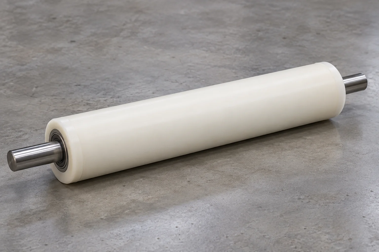
Support and transport products in material-handling systems. Plain, shaft-mounted, bearing and driven arrangements are reviewed to the application.
Discuss this roller →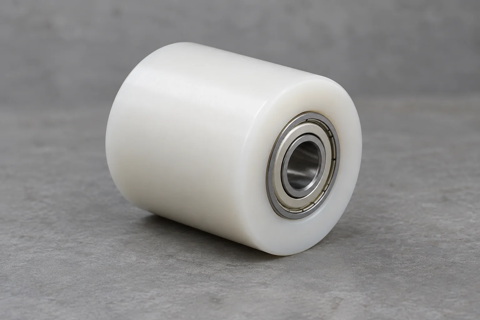
Free-running support rollers that guide material or maintain belt and track position. Specify support, speed and bearing conditions.
Discuss this roller →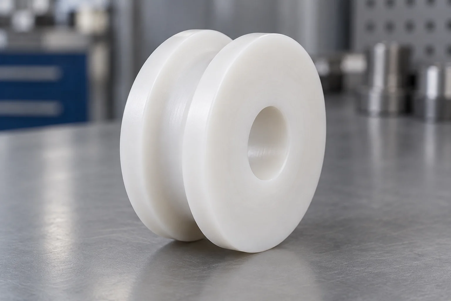
Custom tread grooves for belts, cables, wire, rope and product guidance. Define groove radius, angle, depth and location.
Discuss this roller →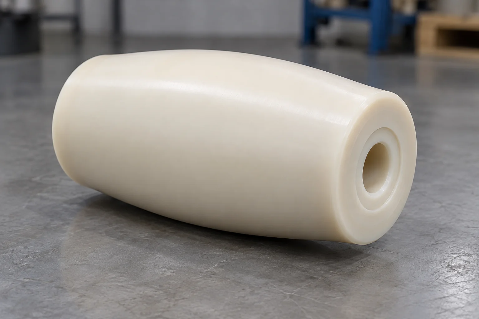
Controlled crowned treads for selected belt-tracking and handling systems. Review the complete belt geometry and tension.
Discuss this roller →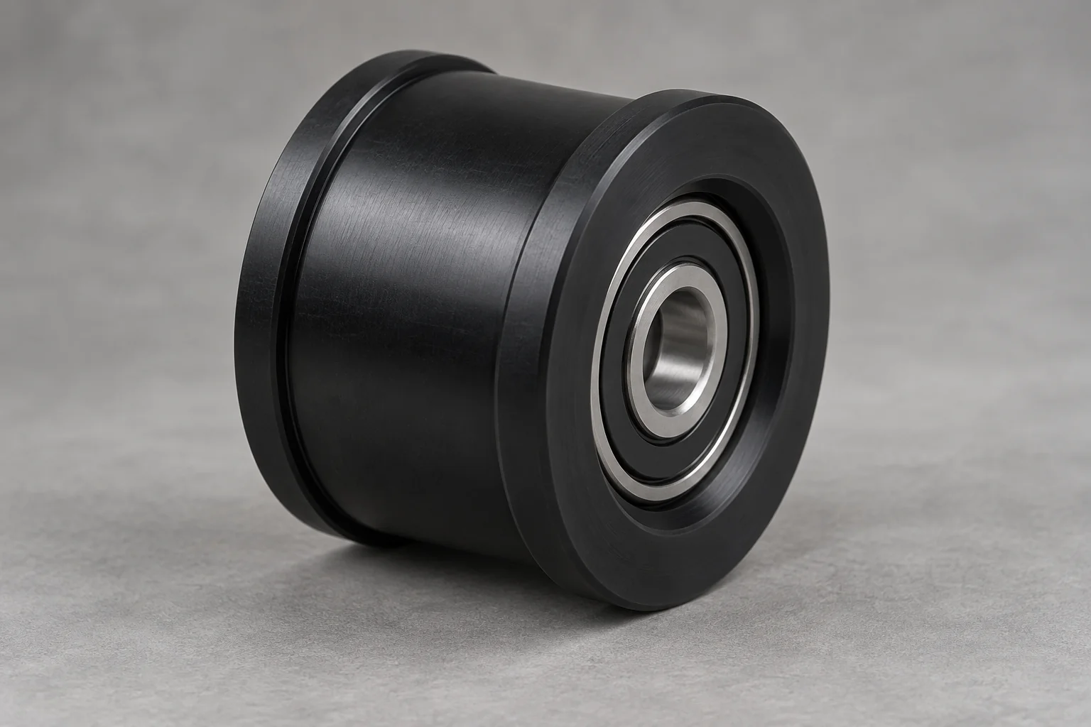
Machined bearing seats and specified installed bearing arrangements. Define bearing reference, retention and inspection state.
Discuss this roller →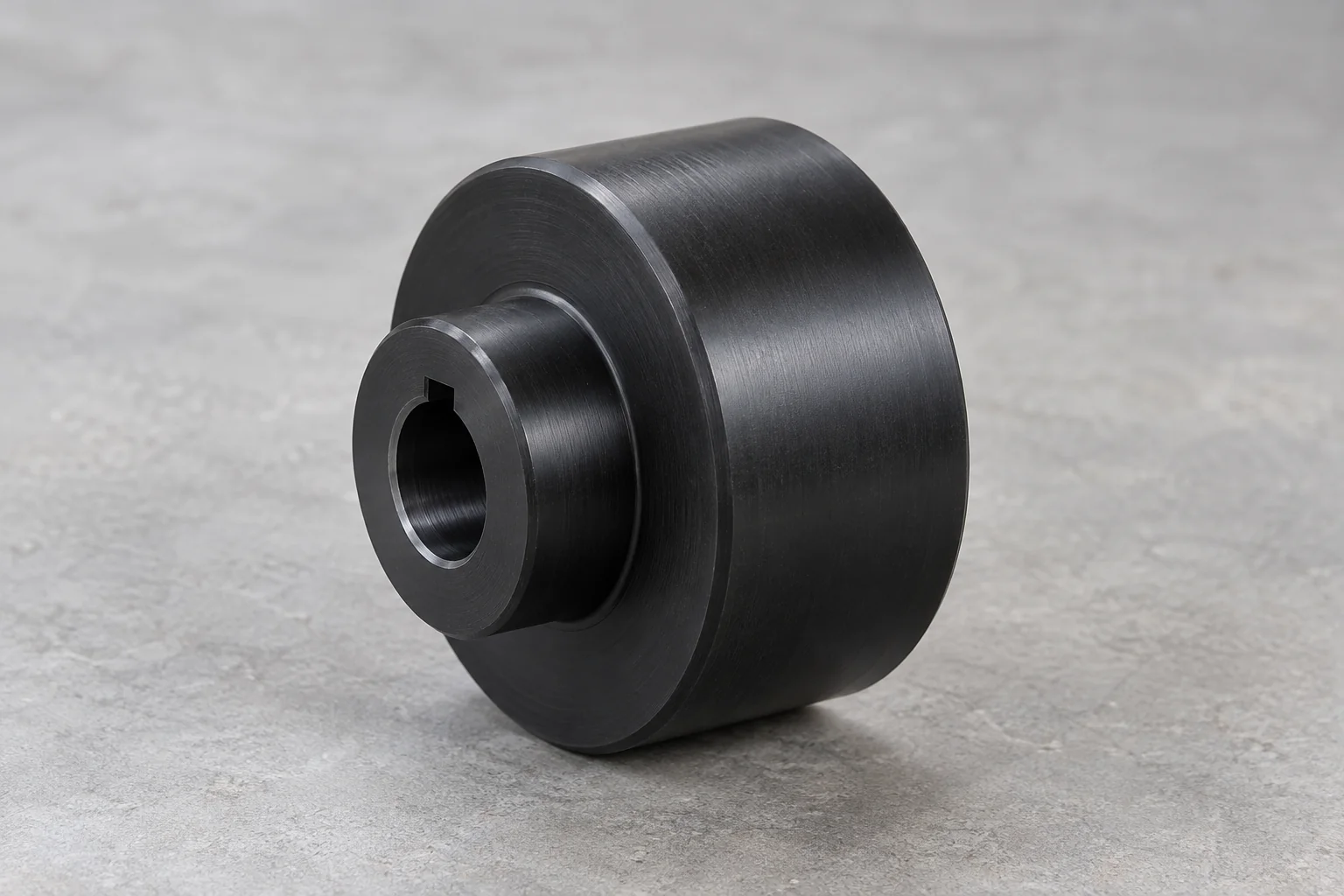
Transfer torque through a shaft, hub, keyway or agreed drive interface. Review tread traction, hub stresses and duty.
Discuss this roller →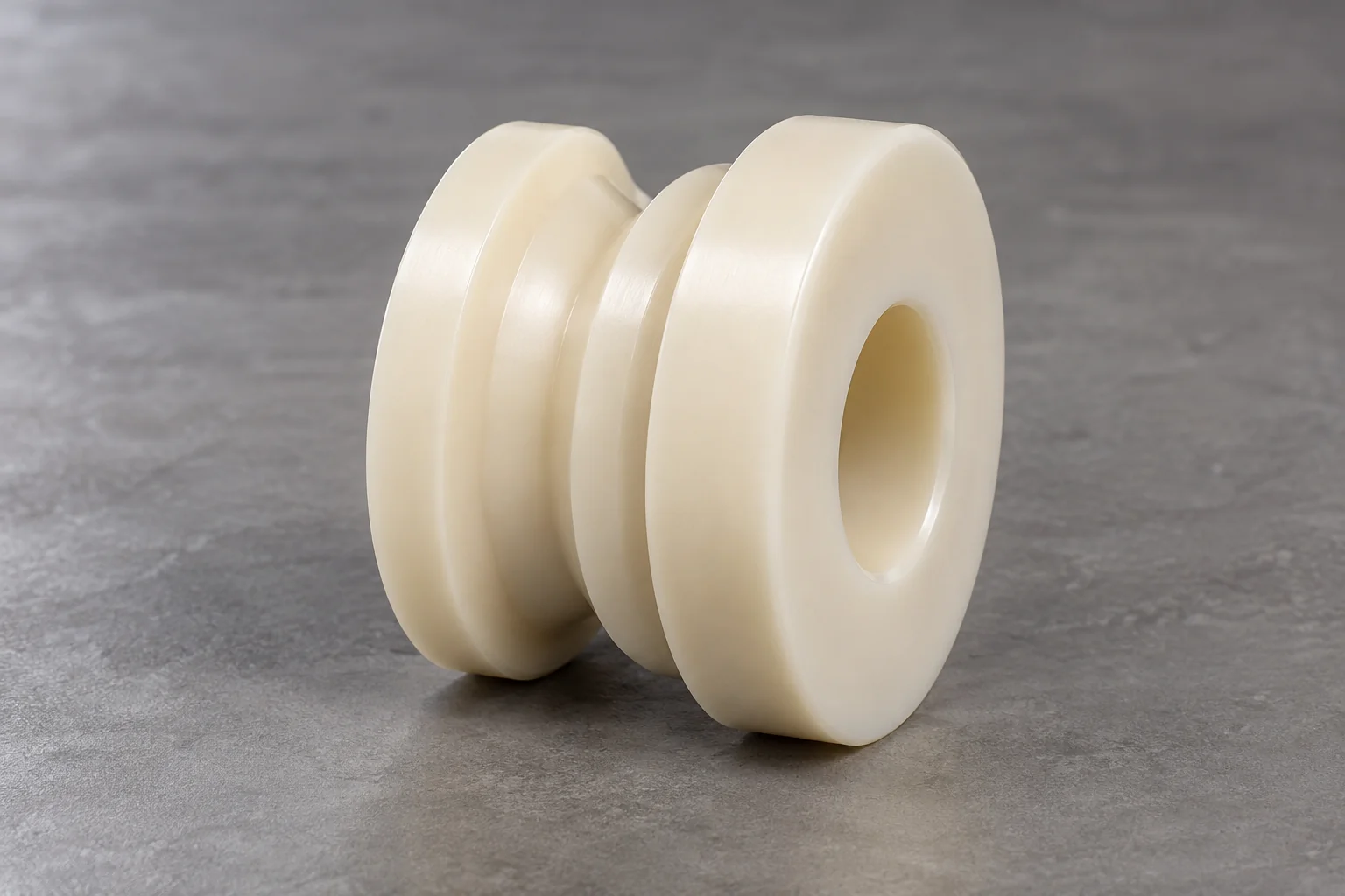
V-grooves, U-grooves, steps, flanges, contoured surfaces and custom tracks made to the approved profile.
Discuss this roller →Plastic rollers are cylindrical or profiled components that support, guide, transport, tension or drive moving products and machine elements. Engineering polymers can provide low mass, corrosion resistance, lower noise and non-marring contact.
Diameter alone does not define roller performance. Material stiffness, shaft support, bearing arrangement, load, rotational speed, groove geometry, surface finish and the operating environment all affect the installed result. A roller wheel, sheave or pulley may share a similar shape, but its contact profile and drive function must be specified.
Select the benefit that matters to your machine, then check the chosen polymer grade and contact conditions.
Lower rotating mass can reduce inertia and make handling easier compared with an equivalent solid metal roller.
Suitable polymers offer options for wet, washdown and chemical exposure. Check the actual medium, concentration and temperature.
Polymer contact can reduce impact and metal-on-metal noise. Bearings, mounting and machine speed still influence the sound level.
A suitable clean polymer tread can protect delicate products. Embedded contamination and abrasive fillers can change that behavior.
Choose the material for the sliding or rolling contact. Self-lubrication is grade- and application-specific, not a property of every plastic.
CNC turning makes nonstandard diameters, faces, grooves, hubs and bearing seats practical without mold tooling.
POM is a useful starting point for precision and dimensional stability, Nylon for tough load-bearing service, UHMW for abrasion-resistant guides and conveyors, and PEEK for demanding temperature or chemical conditions. Final selection depends on the grade and duty.
| Material | Typical fit | Main strength | Review before selection |
|---|---|---|---|
| Nylon / PA | Load-bearing and impact-exposed rollers | Toughness and wear resistance | Moisture absorption changes dimensions; review conditioning, temperature and grade. |
| UHMW-PE | Conveyor, guide and impact-exposed rollers | Abrasion resistance, low friction and impact behavior | Lower stiffness and creep can limit bearing-seat retention or tight runout. |
| POM / Delrin | Precision machinery and stable roller geometry | Low moisture uptake and dimensional stability | Impact and temperature performance depend on grade; compare actual duty with Nylon. |
| PEEK | High-temperature or chemically demanding rollers | Thermal and chemical performance | Higher material cost; use grade data and contact-load limits. |
| HDPE | General industrial and chemical-handling rollers | Economical stock and chemical resistance | Lower stiffness, creep and thermal movement. |
| PET-P | Precision mechanical rollers in low-moisture service | Low moisture absorption and dimensional stability | Notch sensitivity and impact behavior require review. |
| PPS | Technical rollers with thermal or chemical demands | Low moisture uptake and thermal / chemical stability | Brittleness and reinforcement can affect impact and contact wear. |
There is no universal best plastic roller material. Specify the supported load, speed, support span, product contact, cleaning process and temperature range. Food-contact or electrical requirements need the exact material grade and supporting documents.
Define each functional surface and its relationship to the bore or bearing axis. Dimensions are reviewed for manufacturability rather than offered as a fixed stock-size range.
| Parameter | Customization / drawing input |
|---|---|
| Outer diameter | Custom OD with functional tolerance and measurement condition. |
| Roller width / face length | Custom working face and overall length; include assembly clearance. |
| Bore diameter | Custom plain bore, keyed bore or stepped bore. |
| Hub diameter | Custom integral hub diameter and projection. |
| Groove form | U, V, belt, cable or drawing-specific contour. |
| Groove width / depth | Specify width, depth, root radius or angle and axial position. |
| Crown profile | Define crown height, radius or full profile and the working face. |
| Flanges | Custom height, thickness, spacing and edge radii. |
| Bearing seat | Define bearing designation, OD, seat depth, shoulder and retention. |
| Keyway | Specify width, depth, length and angular relationship. |
| Shaft interface | Through shaft, stub shaft, flats, drive connection and retention. |
| Cross holes | Custom location, size, thread and relationship to the running surface. |
| Surface finish | Material- and application-dependent; define working contact faces and acceptance. |
A plastic bearing seat should not automatically use the interference specified for a metal housing. Polymer stiffness, creep, wall thickness and thermal expansion affect bearing retention, ring distortion and installed clearance.
Specify whether the roller turns freely on the shaft or rotates with it. For sliding contact, review shaft finish, clearance, lubrication and the material’s bearing data.
Provide the bearing designation, outside diameter, width and retention method. Review interference with seat wall thickness, polymer grade, assembly method and the full temperature range.
A keyway transfers torque through the bore and hub. Define key size, torque, wall section and retention; assess stress concentration and creep under sustained load.
Provide shaft diameter, length, material, bearing positions and support locations. State whether the shaft is stationary or rotates with the roller.
Define both end connections, engagement length and alignment. Support spacing and end construction influence bending and bearing alignment.
Agree the seat and shaft fits before machining. Excessive interference can distort the polymer or bearing ring; insufficient retention can allow movement after temperature changes or long service. A complete assembly trial may be needed.
The running profile controls where load is carried and how the product or belt is guided. Define mating geometry rather than specifying a groove name alone.
For support and transport. Specify tread diameter, face length, finish and contact pressure; traction is not guaranteed by smoothness alone.
For round products, cable or guided components. Provide root radius, depth, opening width and the mating diameter to avoid concentrated edge contact.
For track, belt or guided-motion applications. Define included angle, root relief, depth and alignment with the mating rail or belt.
A controlled convex profile can influence tracking in selected belt systems. Crown does not correct every tracking problem; belt tension, pulley alignment and conveyor geometry need review.
Load capacity and life must be assessed for the complete roller, shaft, bearing and contact system. An outside diameter or material name cannot establish a universal load rating.
Conceptual beam relationship only. F: load · L: support span · E: modulus · I: section stiffness. Actual roller sizing requires the support, shaft, contact and creep conditions.
Higher contact load increases roller and shaft deflection. Include peak loads, impact, duty cycle and how the load is distributed across the face.
Longer spans increase bending and can alter tracking. Provide the actual distance between supports, not only the roller length.
Speed influences bearing selection, contact heating and balance. Specify RPM, surface speed, start-stop operation and sustained duty.
UHMW, POM and PEEK respond differently under the same load. Modulus changes with temperature and time; sustained deformation requires creep data.
Product hardness, particles, edge loading and cleaning chemicals affect wear. Check contact pressure and any sliding between the tread and product.
For a simplified beam concept, deflection scales with load × support span³ ÷ (modulus × section stiffness). This is a conceptual relationship, not a complete roller-sizing formula: support conditions, load distribution, shaft contribution, contact deformation and polymer creep determine the actual result.
Do not infer roller service life from a material wear ranking alone. Validate critical assemblies at representative load, speed, temperature and contamination levels.
For precision rollers, the relationship of OD to the bore or bearing axis, total runout, bearing-seat geometry and groove location often matters more than tightening every external dimension.
| Feature | Why it matters |
|---|---|
| Roller OD | Product contact, drive ratio and installed clearance. |
| Bore | Shaft clearance or bearing fit. |
| OD-to-bore concentricity | Relationship between the working tread and the rotation axis. Define the datum and the geometric control. |
| Total runout | Rotation consistency, vibration and tracking; specify the inspected surface and datum axis. |
| Roller width | Axial clearance and contact coverage. |
| Groove location | Belt, cable or product alignment. |
| Groove profile | Contact geometry, guidance and local stress. |
| Bearing seat | Retention, alignment and bearing-ring distortion. |
| Face perpendicularity | Axial alignment relative to the rotation datum. |
Specify the datum, inspection setup, measurement temperature and material conditioning. Runout includes the effects of geometry and setup; a runout reading alone does not isolate concentricity. Tight fits and thin walls need a project-specific tolerance review, particularly with UHMW or moisture-sensitive Nylon.
Put the functional requirements on the drawing and review the installed state before production.
Compare stiffness, wear, temperature, moisture, chemicals and product contact; do not select Nylon, POM or UHMW on price alone.
Provide the complete support system, bearing references and whether the roller or shaft rotates.
Allow enough section around bores, grooves and bearing seats to resist clamping, assembly and service distortion.
Agree interference and retention with the bearing specification, polymer grade, wall thickness and temperature range.
Identify the running surface and datum axis, and state whether inspection is on the bare part or assembled roller.
Review fit and clearance at minimum and maximum temperature, particularly for large diameters and steel-bearing interfaces.
Define conditioning and the moisture state used for dimensional acceptance. Installed dimensions can change with humidity.
Provide width, depth, radius or angle, axial location, edge transitions and mating geometry.
CNC turning is the main process for rotational roller geometry. Secondary operations follow the drive features and assembly requirements on your drawing.
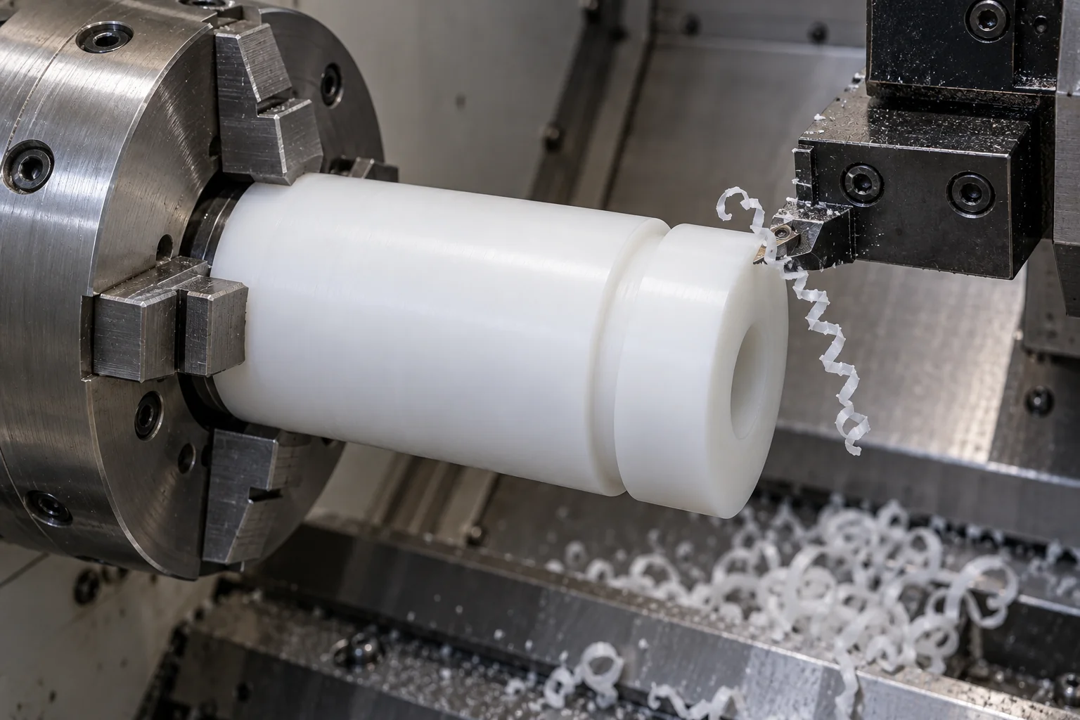
Machine outer diameters, faces, bores, hubs, shoulders, steps and circumferential grooves with suitable support and controlled clamping.
Finish shaft bores and bearing seats in relation to the chosen datum. Review wall thickness, tool access and measurement after release.
Machine keyways, flats, cross holes, drive features and anti-rotation details while preserving their relationship to the roller axis.
Where specified and agreed, install bearings or shafts using a reviewed method. Define retention, assembly force path and installed acceptance.
Check OD, bore, functional runout, groove geometry and drawing dimensions after the agreed stabilization and assembly state.
Plastic rollers are attractive for low mass, corrosion resistance, quieter contact and non-marring handling. Metal often suits designs dominated by stiffness, very high load or heat conduction.
| Factor | Plastic rollers | Metal rollers |
|---|---|---|
| Weight | Generally lower for comparable solid geometry | Generally higher; hollow construction changes the comparison |
| Noise | Can reduce contact and impact noise | Depends on contact, bearings and structure |
| Corrosion | Strong options with a compatible polymer grade | Alloy, coating and exposure dependent |
| Surface marking | Can be lower with suitable clean tread material | Contact hardness and finish can mark products |
| Stiffness | Lower; check deflection and time-dependent creep | Usually higher |
| High-load capability | Limited by geometry, contact stress and temperature | Often better for high stiffness or high-load demands |
| Thermal conductivity | Lower; frictional heat can remain local | Usually higher |
| Chemical environments | Select from compatible polymer grades | Alloy and chemical dependent |
Compare complete assemblies rather than material density alone. A polymer tread on a metal core may be appropriate for some duties, but construction and manufacturing scope require a separate review.
Match the working tread and bearing arrangement to the product being handled and the machine environment.
Guide, idler and transport rollers for product movement, accumulation and belt support.
Product guidance, pinch and handling rollers with defined contact geometry and surface requirements.
Rollers made from specifically documented grades where required. Confirm food-contact conditions, cleaning agents and traceability before ordering.
Precision guide, track and positioning rollers with controlled runout and mounting relationships.
Non-marring contact or electrical insulation where appropriate. ESD behavior requires a specified grade and validation.
Fixture, handling and production-line rollers selected for load, contamination and duty.
Wear-resistant motion and support rollers for custom equipment and OEM assemblies.
Start with functional validation, then retain the material, datum and inspection requirements needed for repeat orders.
Evaluate geometry, material, groove shape, bearing fit, tracking and installed runout before approving the production drawing.
CNC manufacture for custom machinery, replacement assemblies and specialized OEM systems without committing to mold tooling.
Control stock grade, drawing revision, machining program, bearing seats, assembly state and agreed inspection records.
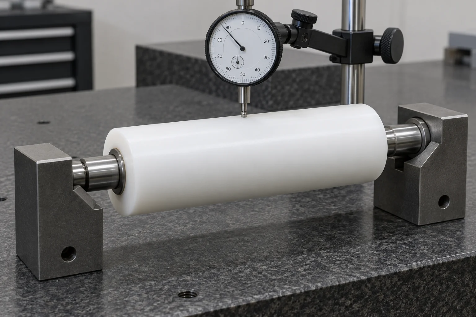
Define the critical features and measurement method with the drawing. The equipment, sampling and report scope are agreed for each project.
Confirm specified polymer grade, stock identification and requested documentation.
Establish functional surfaces, datum axis, acceptance limits and inspection conditions.
Measure outer diameter, bore and width with methods suited to the material and geometry.
Check seat diameter, depth, shoulder and the agreed released or assembled fit.
Use a defined datum setup to assess tread rotation and the specified geometric relationship.
Check radius or angle, width, depth and axial position against the drawing.
Review burrs, edge condition, machining marks and specified working-face acceptance.
Protect tread surfaces, bearing interfaces and component identification during shipment.
Micrometers, bore gauges, indicator setups or profile measurement methods may be appropriate depending on the feature. Agree the actual method before claiming a measurement capability; optical inspection or CMM use is only included when specifically confirmed.
A roller is more than a diameter: material stiffness, support span, bearings, runout, groove profile, speed and load need to be reviewed together.
CNC turning focused on the working tread, bore and axial relationships.
Multiple engineering plastics reviewed against the actual application.
Custom grooves, bores, hubs, flanges and bearing seats.
Bearing and shaft details considered with the mating assembly.
Runout and dimensional acceptance planned around the agreed datums.
A path from fit checks to low-volume and recurring production.
Drive features and specified assembly support where agreed.
Manufacture from approved drawings; samples help establish geometry but wear must be assessed.
Practical answers for specifying, selecting and sourcing custom polymer rollers.
Plastic rollers support, guide, transport, tension or drive products and machine elements. Typical uses include conveyors, packaging machines, automation, product handling and custom industrial equipment.
There is no single best material. POM suits many precision duties, Nylon offers toughness, UHMW offers abrasion resistance and low friction, and PEEK addresses demanding heat or chemical conditions; grade, load and environment decide the final choice.
It depends on the duty. Nylon is generally stiffer and useful for tougher load-bearing service, while UHMW is often chosen for abrasion, impact and low-friction contact. Nylon moisture uptake and UHMW creep need different allowances.
POM is often suitable because of its low moisture uptake, machinability and dimensional stability. The final roller still needs a reviewed datum, runout, bearing fit, temperature range and material grade.
Yes, plastic rollers can be machined with bearing seats and supplied with specified bearings where agreed. Provide the bearing designation, retention method, axial loading and required assembly state.
There is no universal interference value for all plastic rollers. Determine it from the bearing specification, polymer stiffness, creep, wall thickness, operating temperature and retention method; do not automatically copy a metal-housing fit.
Functional tread runout, OD-to-bore relationship, bearing-seat geometry and groove position are often the most important. Specify the datum, measurement setup, temperature, conditioning and whether the part is inspected bare or assembled.
Yes, custom V-groove, U-groove and other drawing-specific roller profiles can be reviewed for machining. Supply groove width, depth, radius or angle, location, mating profile and critical contact requirements.
They can reduce impact and contact noise in suitable applications. Noise also depends on bearing condition, speed, mounting, alignment and the product being handled, so a quieter result should be validated in the machine.
We can review drawings, CAD models and reference samples for custom roller manufacture. A worn sample does not define the original fit or material grade reliably; agree restored dimensions, critical features and an approved drawing before production.
DIAMETER IS ONLY THE START.
Upload your roller drawing, CAD model or sample photographs and provide the material, OD, face width, bore or bearing configuration, groove profile, shaft details, load, speed and operating environment. We can review the geometry and material before quotation. Contact us to arrange any physical reference sample.
Company, name, email and phone are required. Country, part number, quantity and drawing upload are optional. Include the technical details in your drawing package or email; there is no need to complete a long technical form.
info@tops-precision.comSTEP / STP / IGES / X_T / DWG / DXF / PDF or ZIP, maximum 10 MB. Larger packages can be shared by email. Agree confidential-file handling before sending sensitive drawings.