Thermal expansion
Machining heat and ambient temperature can change a dimension. The effect becomes more significant as the measured length increases.

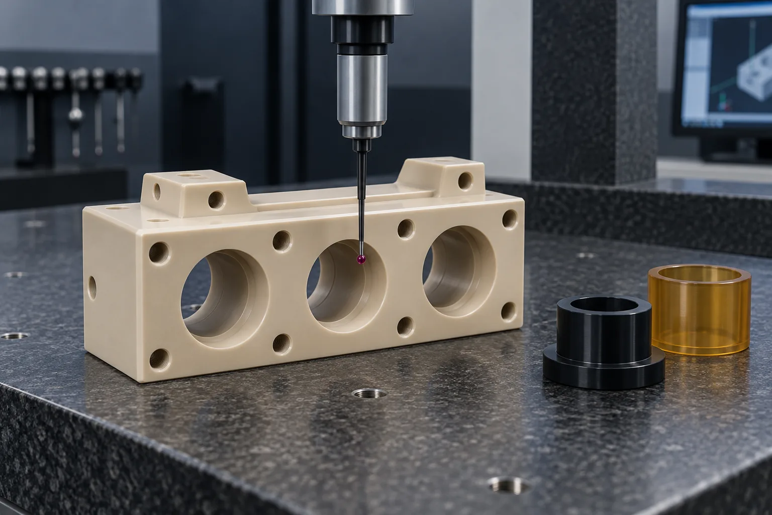
FUNCTIONAL FITS / MATERIAL STABILITY / MEASUREMENT
TOPS Plastics provides precision CNC machining for plastic components with critical dimensional, positional and fit requirements. We review material-specific machining, workholding, staged processing and dimensional inspection for PEEK, POM, PEI, PPS, Nylon, PTFE and other engineering plastics.
Precision starts with a defined condition.
01 / PRECISION REVIEW
The drawing defines the precision requirement. We review the polymer, feature size, support condition and inspection plan before confirming feasibility.
| Capability | Project scope |
|---|---|
| Processes | Precision CNC milling, turning and 5-axis machining; secondary operations selected by feature. |
| Precision focus | Critical dimensions, functional fits, GD&T and relationships between features. |
| Materials | PEEK, POM, PEI, PPS, PET-P, Nylon, PTFE, PC, PMMA and other specified engineering plastics. |
| Inspection | Dimensional verification to the controlled drawing and agreed measurement condition. |
| Quality approach | First-article review, in-process checks and final inspection within the agreed scope. |
| Input | 3D CAD model plus controlled 2D drawing, revision, material grade and quantity. |
| Documentation | Inspection report format, measured features, sampling and material documentation agreed before order. |
| Production | Functional prototypes, validation batches, low-volume orders and repeat production. |
A machine positioning specification is not a finished-part tolerance guarantee. Numerical tolerances, measurement equipment, uncertainty, environmental controls and report requirements must be confirmed for your specific project.
02 / PRECISION REVIEW
Tight tolerance plastic machining controls selected dimensions, geometric relationships or fits within a narrow permitted variation relative to the part’s size and function.
The objective is to control the features that determine assembly, sealing, motion and alignment. General dimensions can often remain less restrictive. This directs machining and inspection effort toward the features that affect performance.
A complete requirement identifies the feature, nominal dimension, allowable variation, datum reference where needed, material condition and acceptance method. A very small tolerance without those conditions can be difficult to manufacture or verify consistently.
04 / PRECISION REVIEW
Material selection should happen before the tolerance strategy is finalized. POM, PEEK, PEI, PPS and PET-P are frequently considered for precision work, but no ranking replaces a grade-specific review.
| Material | Precision starting point | Main risks to review |
|---|---|---|
| POM / Delrin | Often favorable for precision mechanical features | Control heat, stock stress, burrs and the fit condition. |
| PEEK | Often favorable when stock and machining are controlled | Review residual stress, heat and grade-specific behavior. |
| PEI / Ultem | Often suitable for stable precision features | Review stock stress, moisture, heat and chemical compatibility. |
| PPS | Often favorable, depending on grade and direction | Brittleness, filler orientation and tool wear require attention. |
| PET-P | Often favorable for precision wear parts | Review machining heat, edge damage and notch-sensitive features. |
| ABS | Useful for many precision prototype features | Heat and asymmetric removal can contribute to movement. |
| Polycarbonate | Feasibility depends strongly on stress and geometry | Review cracking, compatible fluids and surface requirements. |
| Nylon | Condition-sensitive | Define dry, conditioned or service-state dimensions. |
| PTFE | Highly sensitive for demanding close fits | Flexibility, creep, measuring force and thermal expansion. |
| UHMW | Highly sensitive for demanding close fits | Low rigidity, thermal movement and supported measurement. |
| HDPE / PP | Condition-sensitive for close tolerances | Thermal movement, creep and feature support. |
These are qualitative selection considerations, not certified capability ratings. Filled and unfilled grades, stock form, fiber direction, temperature and part size can change the result. Select the material for function first, then qualify the required dimensions.
Compare engineering plastic materials →05 / PRECISION REVIEW
The final dimension is the result of a complete manufacturing and measurement system.
Specify the exact designation, fillers, supplier restrictions and any required evidence. Reinforcement can introduce directional behavior.
Extruded, compression-molded, annealed and stress-relieved stock can respond differently to material removal.
Thin walls, large plates, long spans and uneven removal increase the need for support and staged processing.
Fixture pressure and support locations affect the shape being cut. Avoid using clamp load to conceal movement.
Balanced roughing, suitable cutting tools and allowance for finishing help manage heat and released stress.
Machining temperature, stabilization and measurement temperature all affect dimensional interpretation.
Free-state, supported and assembled measurements may give different results. Match the method to the specified condition.
06 / PRECISION REVIEW
Select the process around the functional surfaces and datum relationships, then confirm how each critical feature will be inspected.
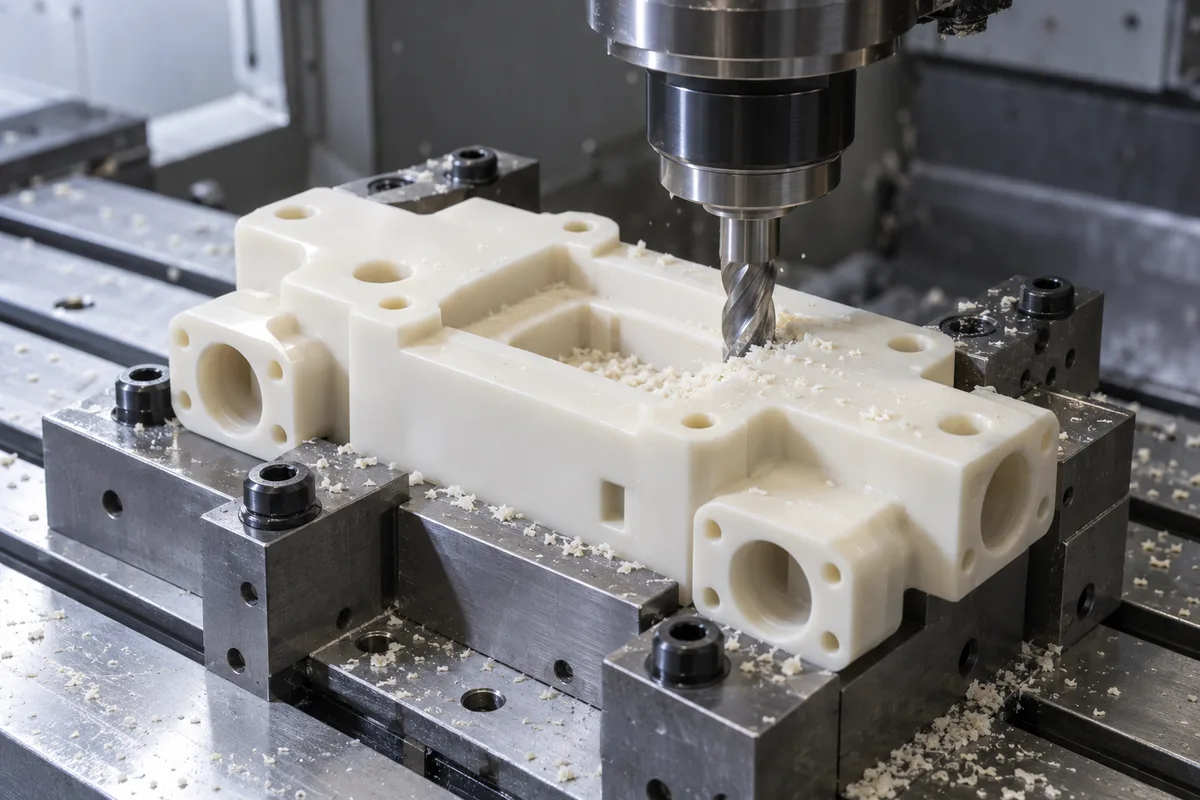
For precision housings, manifolds, mating faces, bores, pockets and features on multiple faces. Plan datum transfer and finishing access together.
Review this process →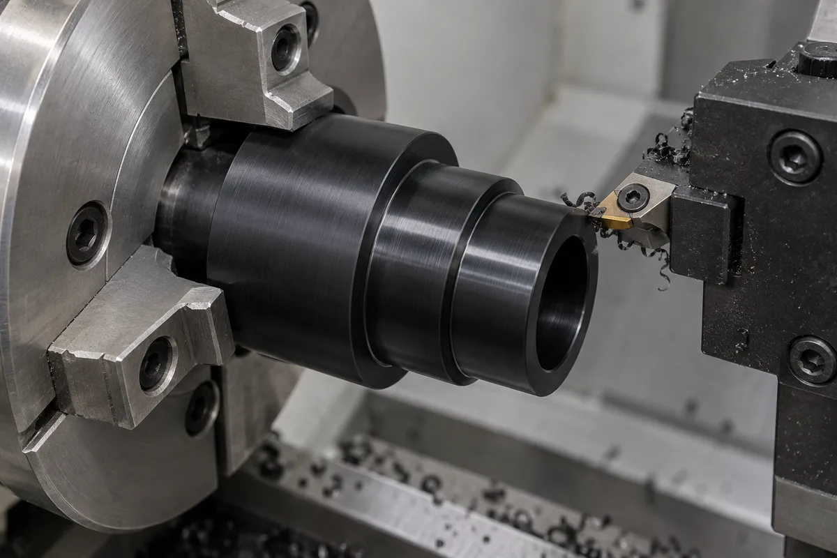
For bushings, bearing components, sleeves and rollers with controlled diameter, fit and OD/ID relationships. Review chuck pressure, wall thickness and released dimensions.
Review this process →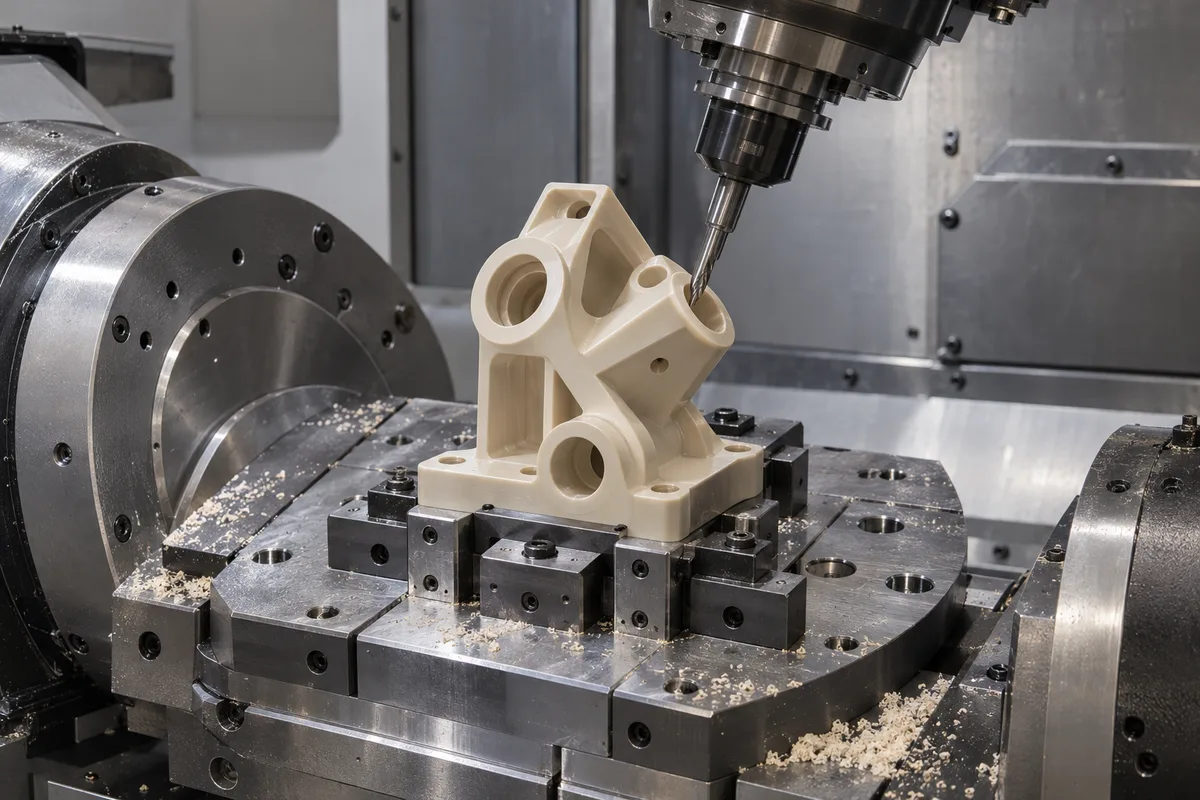
For compound-angle features, multi-face positional requirements and complex datum relationships. Fewer setups may help datum control, but do not remove material movement.
Review this process →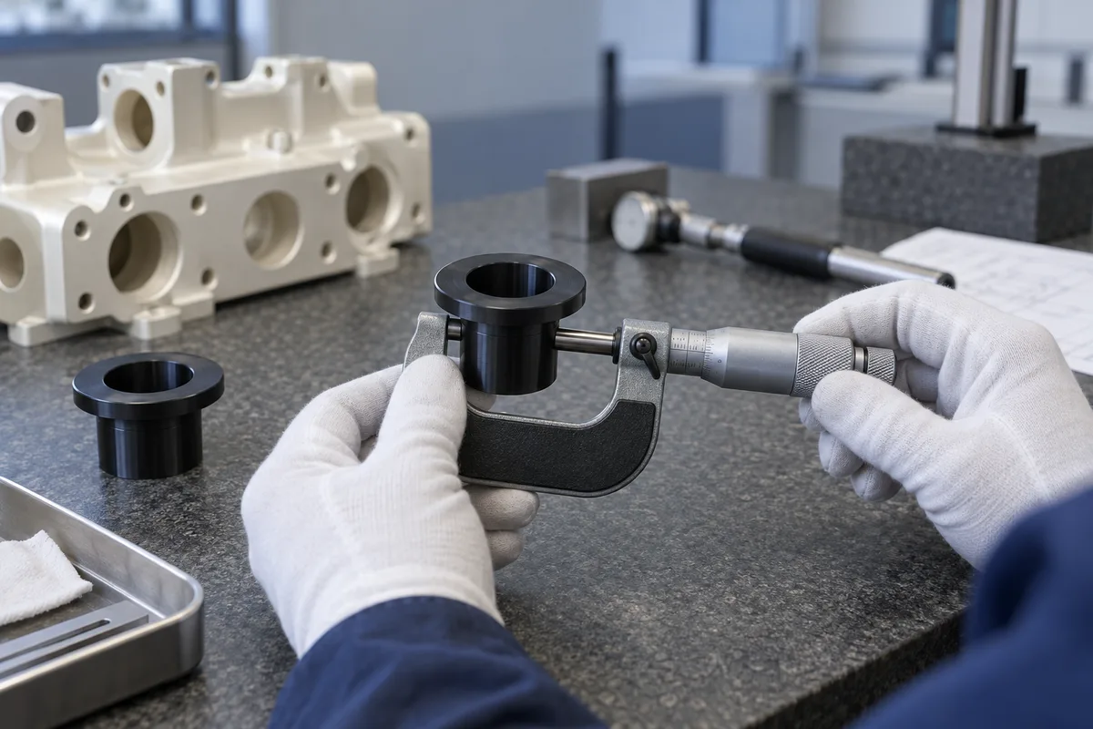
Boring, reaming, thread finishing, polishing and inspection-fixture operations may be considered when the feature and grade justify them. Finishing must preserve the required geometry.
Review this process →07 / PRECISION REVIEW
Use the material response to set the machining sequence, support and inspection condition.
A useful starting point for mechanical fits. Control cutting heat, burrs and stock stress; verify diameters after release and stabilization.
Review stock history, tool condition and heat. Stress relief may be considered for demanding geometry, using an approved grade-specific process.
State whether dimensions apply dry, conditioned or in the service state. Packaging and inspection timing must be consistent with that requirement.
Use realistic fits and light, repeatable measuring forces. Support soft features and check whether clamp pressure or sustained load changes the result.
Restrict tight requirements to functional features. Review thermal movement, creep, support and the benefit of a more stable material when function permits.
Changing the grade after drawing approval can change the tolerance feasibility. Treat substitutions as an engineering change and review the acceptance plan again.
08 / PRECISION REVIEW
A functional datum structure defines how the part sits in its assembly and how critical features relate to that location. It can be more useful than a chain of tight bilateral dimensions.
Relate the bore to the functional references. The actual datum selection and geometric control must follow your drawing standard and assembly.
Locate bores relative to the mounting and locating datums used in assembly. Include any applicable modifiers on the drawing.
Apply where sealing or mounting depends on surface form. Define the released or supported condition for flexible parts.
Control a mating face or bore axis relative to the functional datum rather than relying on a chain of linear dimensions.
Use an appropriate profile requirement for complex housings or contours, with a clear datum reference and evaluation method.
For turned parts, select position or runout controls that express the function. If a legacy concentricity callout appears, clarify the governing drawing standard and how it will be measured.
Relate mating plates, guides and sliding faces to the surface that actually locates the component.
Use the GD&T standard and revision stated on the drawing. Datum simulation, restraint, probing strategy and allowable measurement force should be resolved before production.
09 / PRECISION REVIEW
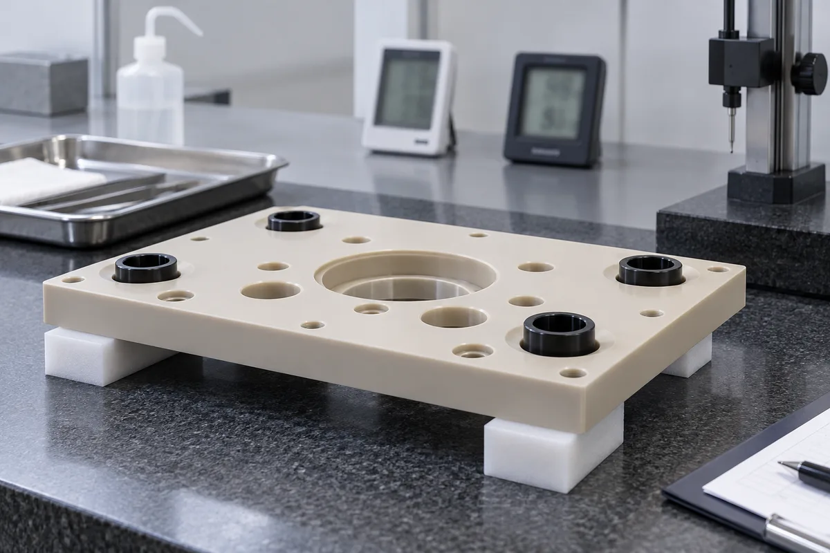
A dimension can change between machining, inspection and service as temperature changes. Stabilize the part and measuring equipment before evaluating close tolerances.
Finish machining
Release the fixture
Allow thermal stabilization
Inspect in the agreed condition
Record the result and condition
State the inspection temperature or agreed reference condition and the allowed variation when relevant. Stabilization time depends on material, mass, section thickness and the environment; one waiting time cannot cover every part.
Consider the temperature difference between inspection and use. A fit that works at room temperature may behave differently in a hot assembly. Thermal estimates should use grade-specific data and be validated when performance is critical.
10 / PRECISION REVIEW
Hygroscopic materials absorb moisture and can change size. The required material state is part of the dimensional specification.
Moisture can have a substantial effect. Define dry, conditioned or service-state acceptance and the conditioning procedure.
Typically less moisture-sensitive than Nylon, but use the exact grade data and specified environment.
Low moisture uptake can be useful for dimensional stability; confirm the grade and actual service conditions.
Often less moisture-sensitive than Nylon, but these materials are not interchangeable. PEI and filled grades still require their own conditioning review.
For moisture-sensitive polymers, record the required state, conditioning method, inspection timing and protective packaging. Drying or conditioning is not an automatic production step; it must be appropriate for the material and agreed requirement.
11 / PRECISION REVIEW
Annealing or staged machining may be appropriate when heavy removal, thin walls, tight flatness or precision features make stress movement likely. It is not necessary for every plastic part.
Confirm qualified stock
Rough machine
Stress relief if specified
Stabilize
Finish machine
Final inspection
PEEK, PEI, Acrylic and other polymers can retain stock stress that becomes important during demanding machining. Review stock supplier guidance, material transitions, support, dimensions and the complete thermal cycle before specifying treatment.
Do not use a generic annealing temperature across polymers. Any approved cycle, intermediate allowance and inspection stage should be documented. Where treatment is supplied externally, agree the route and supporting records before order.
12 / PRECISION REVIEW
A flexible part can be forced into shape by a fixture and move when released. Machining and inspection should reflect the required finished-part support condition.
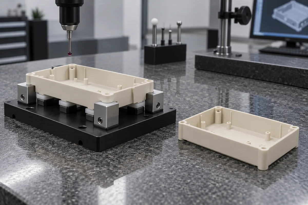
Spread load across suitable supported areas rather than concentrating it on a thin wall or precision bore.
Locate repeatably on functional areas while protecting delicate features and finished surfaces.
Consider these for suitable flat components after reviewing sealing area, holding force and possible deformation.
Inspect after release when the drawing requires free-state acceptance. For restrained requirements, define the fixture and permitted load.
Do not tighten a measurement fixture until a distorted part appears to pass. Agree whether acceptance applies free, supported or assembled, and reproduce that state consistently.
13 / PRECISION REVIEW
Feature stiffness, access and size determine whether the drawing needs a different support, process or tolerance strategy.
| Feature | Main risk | Review approach |
|---|---|---|
| Thin walls | Deflection and clamp distortion | Increase local stiffness or define support and restraint. |
| Long unsupported features | Bending during cutting and measurement | Shorten spans or add distributed support. |
| Large flat plates | Thermal and residual-stress movement | Review balanced removal, stabilization and measurement condition. |
| Deep bores | Tool reach, heat and chip evacuation | Review depth, finishing access and bore measurement. |
| Small precision holes | Burrs, edge damage and measurement access | Specify edge condition and a suitable measurement method. |
| Multi-face features | Datum transfer between setups | Plan datum location and setup sequence. |
| Press fits | Temperature, hoop stress and creep | Review mating materials, assembly force and service load. |
| Long slender turned parts | Deflection and chuck influence | Review support, sequence and released straightness. |
| Optical plastics | Stress cracking and surface requirements | Review compatible fluids, finish and dimensional acceptance. |
14 / PRECISION REVIEW
Select metrology to match the feature, material stiffness and acceptance condition. A CMM is not automatically the best tool for every flexible plastic feature.
| Method to consider | Suitable feature or task | Important limitation |
|---|---|---|
| CMM | Feature position, profile and datum-related geometry | Probe force, restraint, access and uncertainty must suit the part. |
| Optical comparator or vision | Small edges, profiles and accessible features | Lighting, transparency and edge definition can affect the result. |
| Height gauge | Heights and accessible relationships to a datum plane | Support and datum seating must be repeatable. |
| Bore gauges and micrometers | Diameters and thicknesses | Contact force can distort soft surfaces or thin walls. |
| Thread gauges | Specified functional thread acceptance | Agree gauge class, engagement and any soft-material limitations. |
| Surface measurement | Specified texture or surface condition | Choose contact or non-contact evaluation appropriate to the surface. |
| Custom fixtures | Assembly-related location and supported-state checks | Define restraint, loads and correlation to the drawing. |
This is an inspection-planning guide, not an inventory claim for TOPS equipment. Required equipment availability, calibration, resolution, measurement uncertainty, sampling and report format are confirmed in the quotation. A requested CMM report or specialized inspection must be explicitly included in the agreed scope.
Use a repeatable method, record the material and environmental condition where relevant, and relate each result to the controlled drawing revision. Resolve conflicting measurement methods before accepting a close tolerance.
15 / PRECISION REVIEW
Turn the approved first article into a repeatable process and inspection plan. Subsequent batches must use the same controlled requirements.
Drawing and GD&T review
Material and stock verification
First-article machining
First-article inspection
Corrective adjustment if needed
Controlled production
In-process checks
Final inspection
Agreed inspection report
Set checkpoints for critical features, tool wear and dimensions that can move after release. A first article is evidence for the agreed part and condition; it does not by itself establish long-term process capability. Statistical capability studies, full inspection and customer-specific FAI formats need a separate agreed scope.
Plan a low-volume or repeat order →16 / PRECISION REVIEW
Clear functional requirements make the part easier to manufacture and the result easier to verify.
Identify dimensions that determine sealing, motion, location and assembly. Avoid imposing the tightest limit everywhere.
Choose stable locating features that represent the assembly and can be reproduced in inspection.
Include relevant temperature, moisture state, timing and support requirements.
Avoid thin walls around close-fitting bores where function allows. Review the effect of pressing or clamping.
Use a coherent datum scheme and appropriate GD&T for functional relationships.
Review differential expansion between the plastic part and its mating components.
State fillers, stock restrictions and permitted substitutions. Filled grades may behave differently by direction.
For flexible panels and housings, state the required restraint and the condition in which acceptance applies.
17 / PRECISION REVIEW
These component families illustrate the feature relationships we can review. Each drawing is assessed for manufacturability and acceptance conditions.
Bore and outside-diameter fits with controlled seating faces.
Fit, running clearance and load-related geometry.
Port position, sealing faces and intersecting passages.
Locating features, flatness and specified cleanliness or material requirements.
Mounting position, clearances and exact electrical-grade requirements.
Mating faces, locating bores and assembled alignment.
Seat geometry, sealing lands and functional interfaces.
Instrument locating features, housings and controlled revisions.
Alignment, profile and specified cosmetic or optical acceptance.
Diameter, runout and bearing interfaces.
Thickness, parallelism and locating geometry.
Compound faces and datum-related positional features.
18 / PRECISION REVIEW
Fit, alignment, sealing and positional accuracy drive these applications. Material purity, compliance and qualification requirements must be specified separately.
Equipment fixtures and precision interfaces; exact purity, outgassing and cleaning requirements need application-specific review.
Housings, fixtures and instrument components to controlled drawings. Medical suitability or regulatory acceptance is not implied by the polymer name.
Lightweight high-performance components with specified material, traceability and inspection requirements.
Test fixtures, insulators and precision housings with defined mounting and alignment.
Manifolds, valve parts and sealing interfaces reviewed for media, temperature and pressure.
Guides, rollers and motion-system components with functional clearances and positioning requirements.
19 / PRECISION REVIEW
Our review begins with the conditions that make a tolerance meaningful: the material, geometry, temperature, moisture and measurement state.
Assess polymer behavior together with the drawing instead of applying a metal-machining assumption.
Confirm grade, stock form and the need for conditioning or staged processing.
Clarify functional references and how requirements will be verified.
Plan support and clamp locations around feature stiffness and finished-part condition.
Select the process combination that fits the geometry and datum relationships.
Agree critical measurements and release criteria before committing the full run.
Identify checks that can reveal movement, wear or setup drift during production.
Discuss practical changes to unnecessary restrictions while preserving the part’s function.
Send the tolerance that your assembly needs. We will review its feasibility and the evidence required before quotation, rather than promise one number across every material and component.
20 / PRECISION REVIEW
The workflow records the engineering decisions that connect your drawing to the finished-part measurements.
Provide revision, quantity, critical features and the assembly function.
Identify exact material, fillers, supplier restrictions and required documentation.
Resolve datums, geometric controls, fits and drawing ambiguities.
Agree temperature, moisture, support, measurement methods and reports.
Confirm what can be quoted and which requirements need discussion.
Choose locating surfaces, clamp support and roughing/finishing stages.
Remove material with appropriate support and finishing allowance.
Use the approved grade-specific route and intermediate checks.
Produce functional dimensions in the reviewed material condition.
Review the agreed evidence and make corrective changes if needed.
Follow the released setup, revision and measurement checkpoints.
Verify acceptance, prepare the agreed report and protect parts for shipment.
21 / YOUR QUESTIONS
It depends on feature size, material, geometry and function. A tolerance is tight when the permitted variation is small relative to the material movement and manufacturing or measurement uncertainty involved. Send the actual drawing; no universal numerical threshold covers every polymer.
POM, PEEK, PEI, PPS and PET-P are often considered for precision work. The best choice must also meet load, temperature, media and electrical requirements. Exact grade, stock condition and geometry determine whether the requested tolerance is realistic.
Many plastics have greater thermal expansion, lower stiffness and more sensitivity to clamping, moisture or released stock stress than common engineering metals. A dimension can change after machining, so the finished-part condition and inspection method matter.
Both can be suitable for precision components when the grade, stock, geometry and process are controlled. This does not establish one guaranteed tolerance for every PEEK or Delrin part. Critical dimensions and inspection conditions need individual review.
Nylon can absorb moisture and change dimensions as its moisture content changes. Temperature, residual stress and fixture release can also contribute. Specify whether dimensions apply dry, conditioned or in the service state.
Dimensions change as the polymer expands or contracts. The effect depends on the exact grade, direction, measured length and temperature difference. Allow stabilization and agree the inspection condition; assess service-temperature fits separately.
Not always. Stress relief or staged machining may help demanding geometry or heavy stock removal, but the need and thermal cycle depend on the grade and stock history. Any treatment should follow an approved material-specific process.
Start from the assembly function and select reproducible datums. Apply geometric controls to functional relationships and specify the governing standard. For flexible components, clarify free-state or restrained acceptance and the inspection fixture.
Use a method suited to the feature and stiffness: dimensional gauges, optical methods, CMM or dedicated fixtures may be considered. Agree equipment availability, measuring force, support, environmental conditions, uncertainty and reporting before order.
No. Tolerance capability must be qualified by material, grade, geometry, size and inspection condition. A requirement accepted for one component cannot automatically be applied to another polymer or part design.
DRAWING + CONDITIONS + ACCEPTANCE
Upload your 3D CAD model and controlled engineering drawing. Identify critical dimensions, the tightest required tolerance, GD&T, datum scheme, exact material grade and the assembly function. Our team can review feasibility and propose a machining and inspection approach before quotation.
Include filled or unfilled grade, overall size, quantity, service temperature, moisture condition, inspection temperature, support or restraint, and any required FAI, CMM report or material certificate in your drawing package or email. Company, name, email and phone are required; country, part number, quantity and drawing upload remain optional.
info@tops-precision.comSTEP / STP / IGES / X_T / DWG / DXF / PDF or ZIP, maximum 10 MB. Larger files can be shared by email. Agree confidential-file handling before sending sensitive drawings.