01
Plastic Bearings
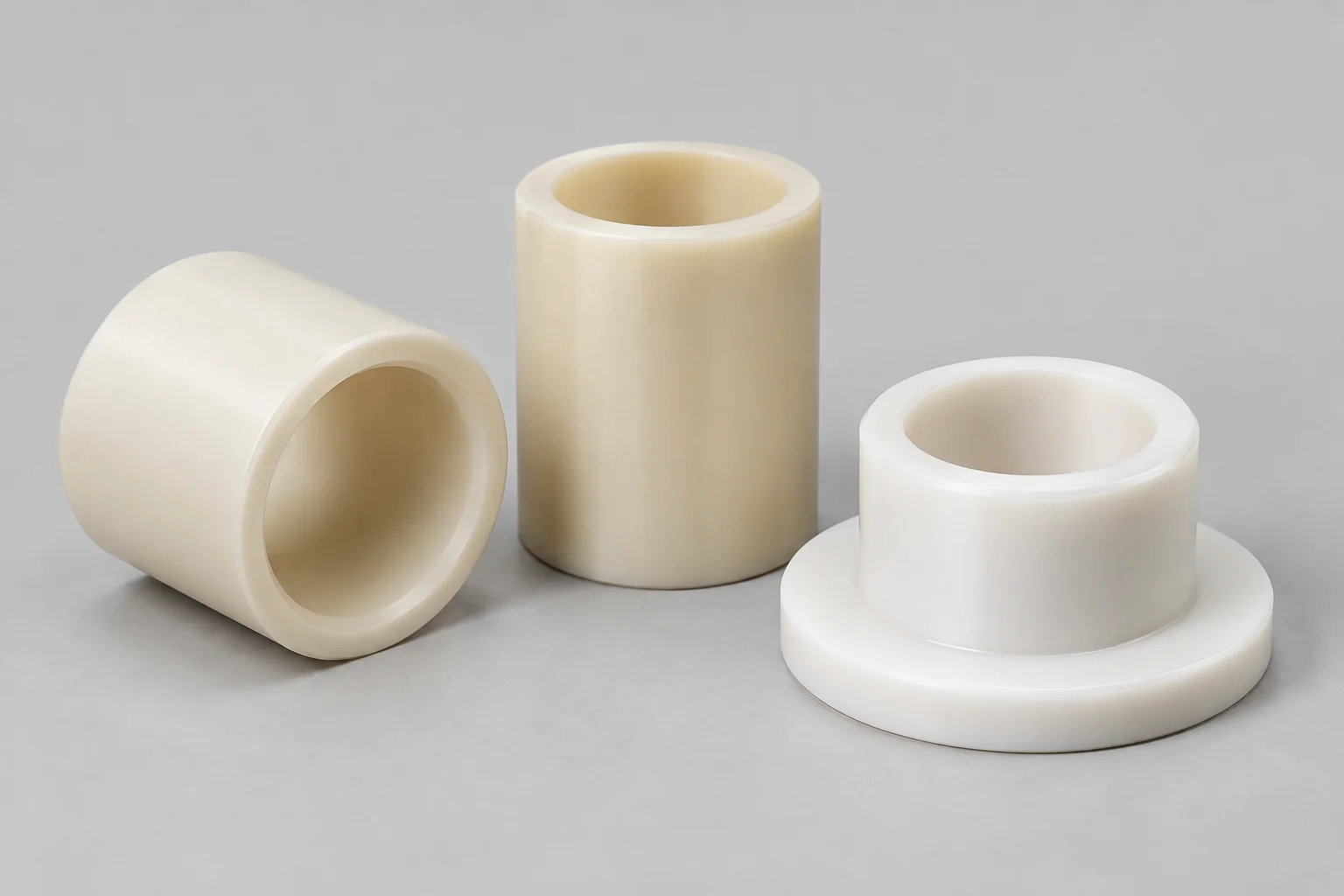
Sleeve and journal bearings, thrust interfaces and industrial pivots for defined shaft, load and lubrication conditions.
Explore component details →
MACHINE FUNCTION · WEAR · REPLACEMENT
TOPS Plastics manufactures custom CNC machined plastic components for industrial machinery, production equipment, conveyors, packaging systems, material-handling systems and OEM machines. We machine POM/Delrin, Nylon, UHMW, PEEK, PTFE, PPS and other engineering plastics for bearings, bushings, rollers, gears, wear pads, guides, housings, manifolds and custom mechanical components.
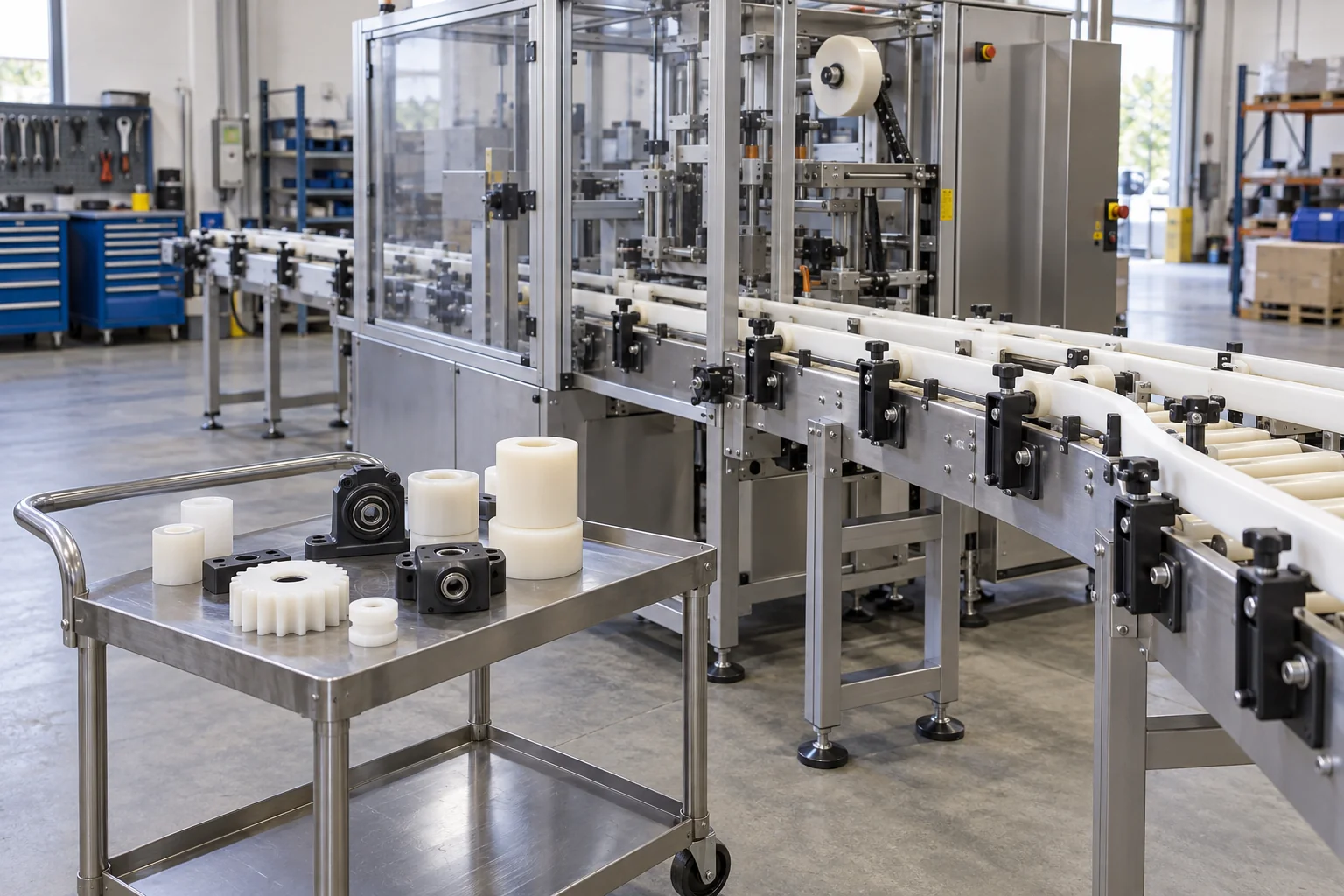
Define what the component must do in the machine before choosing a material or machining route.
| Capability | TOPS Plastics |
|---|---|
| Typical parts | Bearings, bushings, rollers, gears, wear pads and housings |
| Materials | POM, Nylon, UHMW, PEEK, PTFE, PPS and specified grades |
| Processes | CNC milling, turning, 5-axis machining, drilling and tapping |
| Key requirements | Wear, friction, load, temperature and dimensional stability |
| Production | Replacement parts, prototype, low-volume and repeat production |
| Input | STEP, CAD, 2D drawings, dimensioned sketches and worn samples |
| Inspection | Drawing-based dimensional inspection |
| Hardware | Inserts, bearings, pins and fasteners where specified |
Choose a component family, then define its machine duty, material and functional interfaces.
Sleeve and journal bearings, thrust interfaces and industrial pivots for defined shaft, load and lubrication conditions.
Explore component details →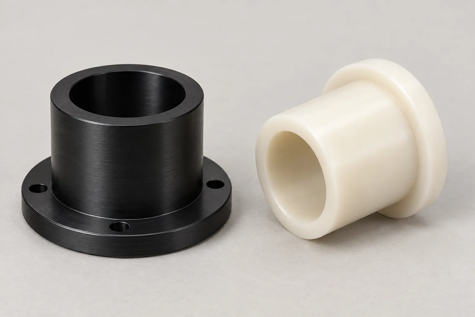
Shaft guides, sliding sleeves and pivot-point components with specified free and installed clearances.
Explore component details →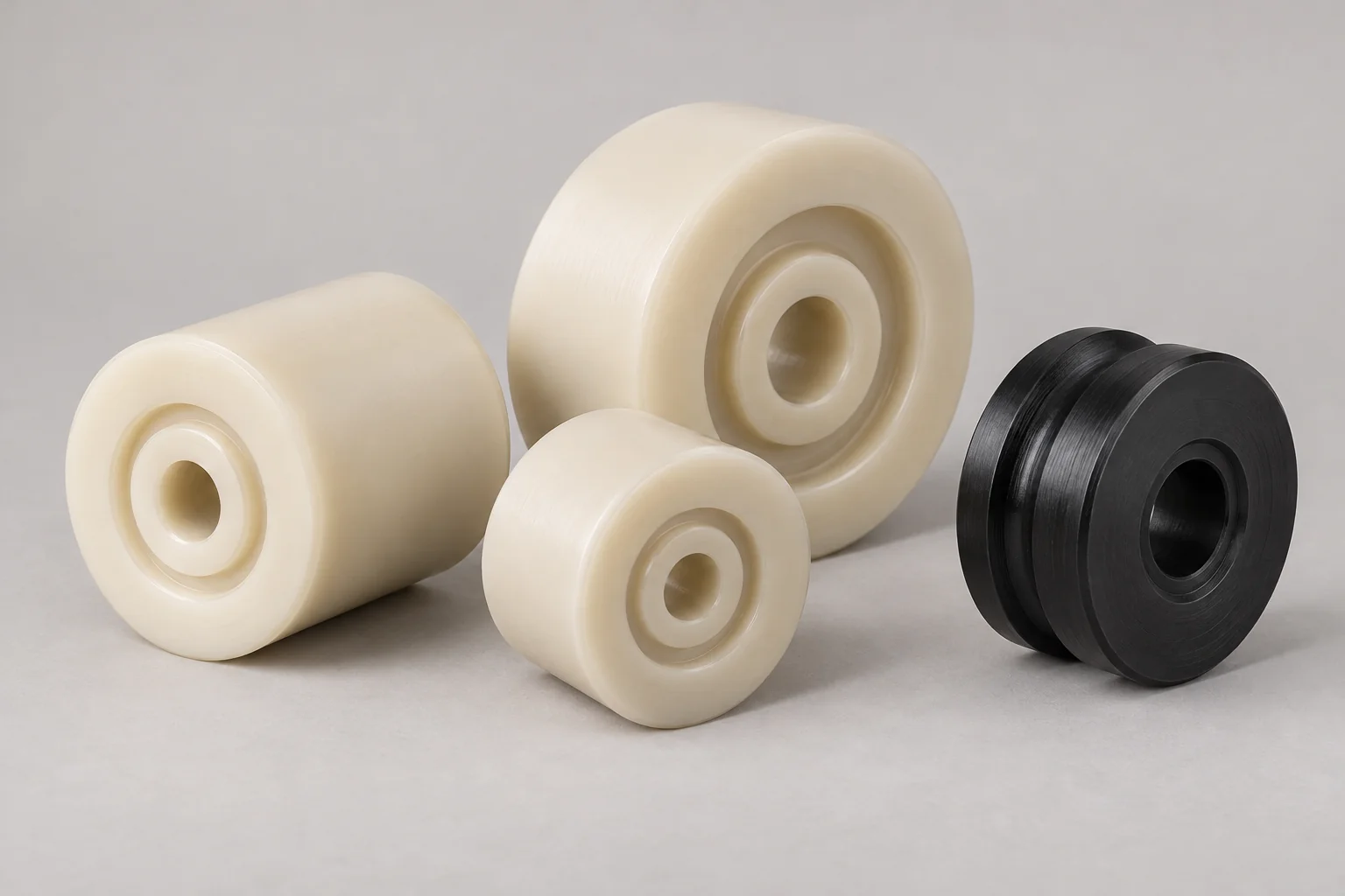
Conveyor, guide, packaging and material-handling rollers with controlled bores, contact profiles and runout.
Explore component details →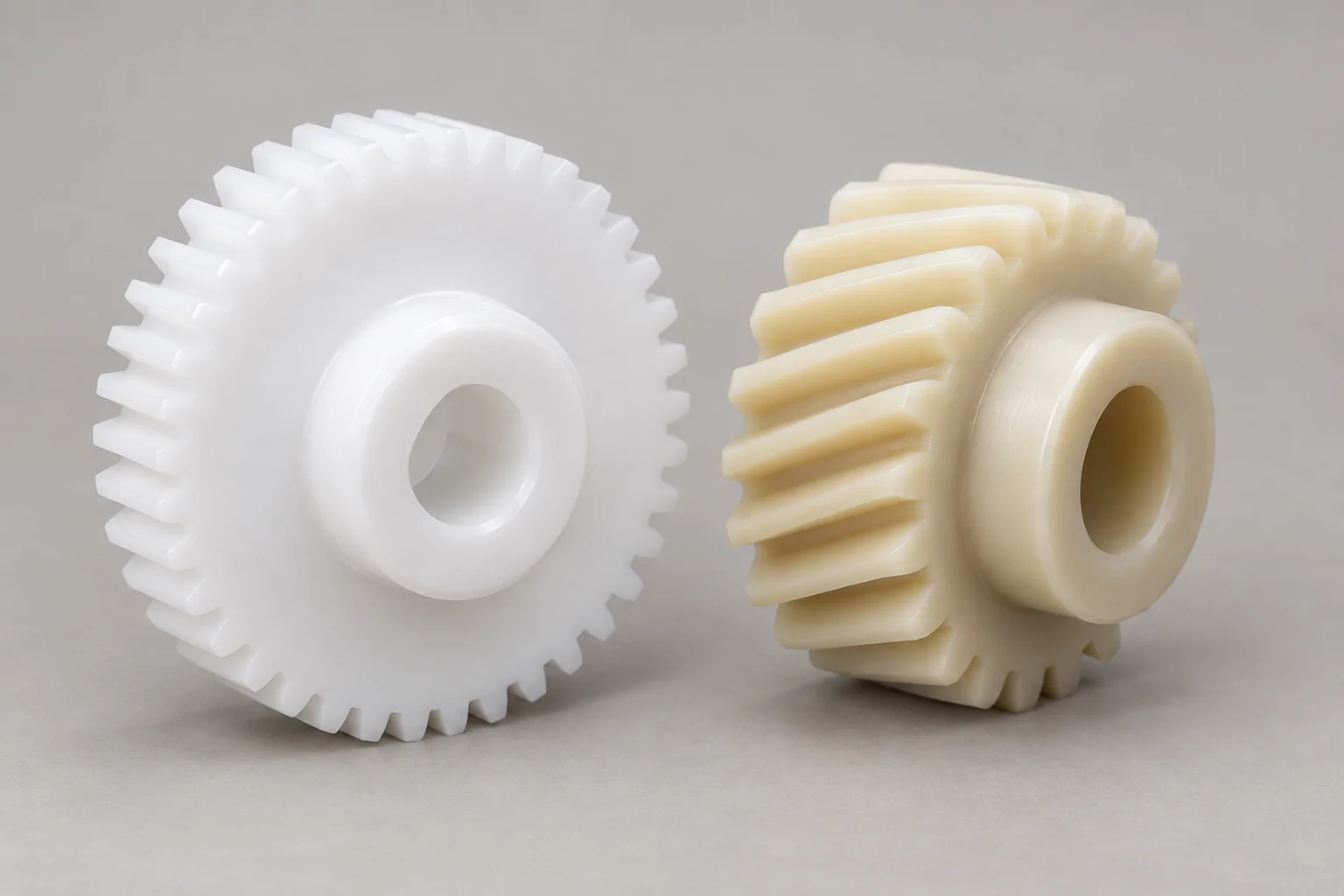
Drive, actuator and indexing components with defined tooth geometry, torque, backlash and mating gears.
Explore component details →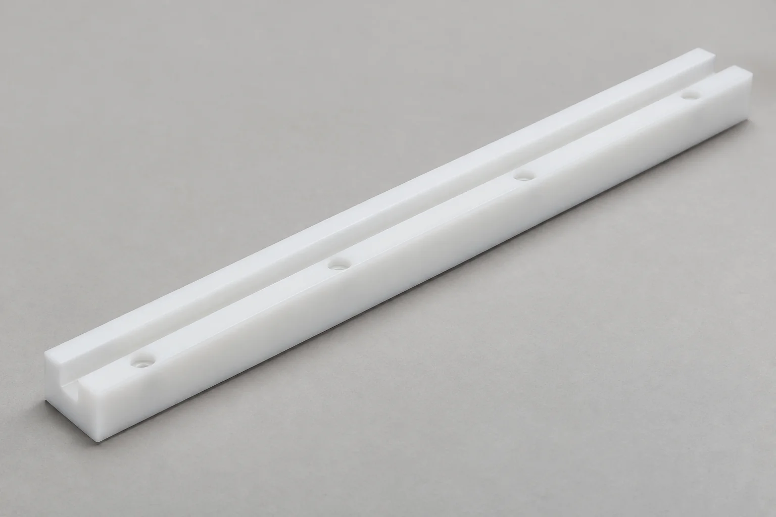
Slide-rail pads, guides, telescopic wear blocks and replaceable contact surfaces with a planned wear allowance.
Explore component details →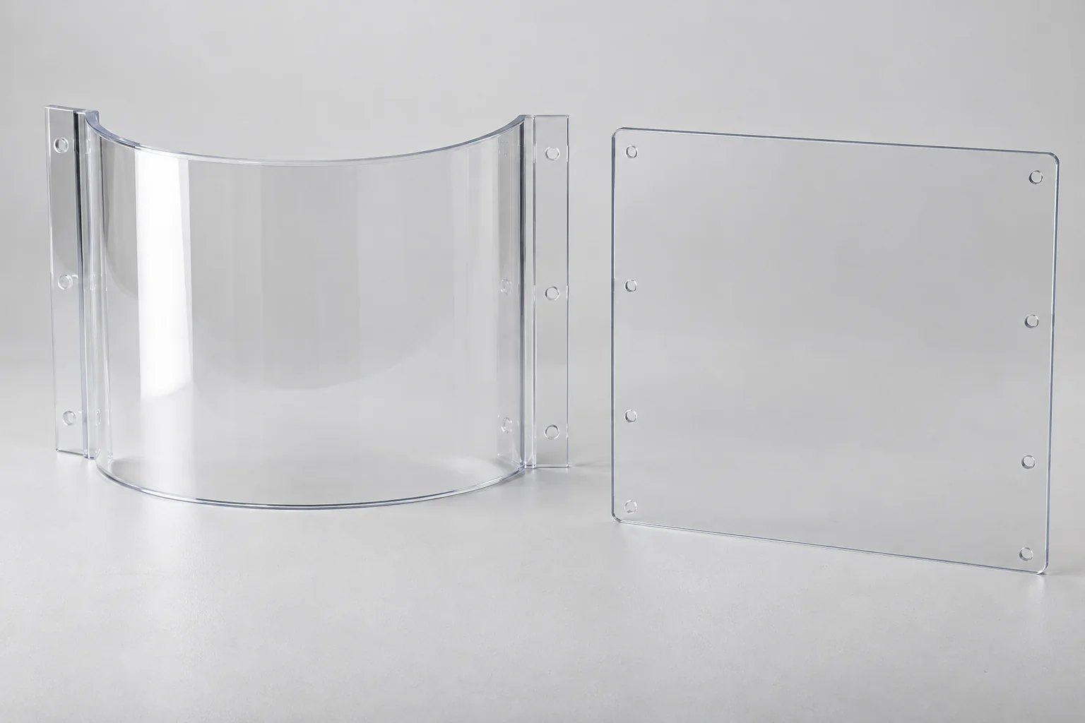
Viewing panels, machine covers and protective barriers made to an approved guard design and mounting specification.
Explore component details →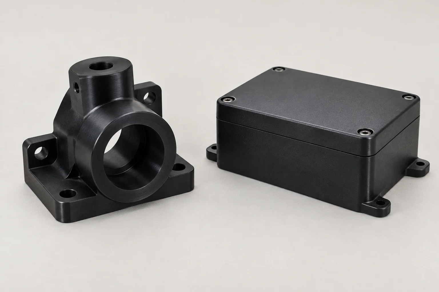
Sensor, motor and control housings with accurate machine interfaces, access and specified environmental requirements.
Explore component details →Plastic Enclosures →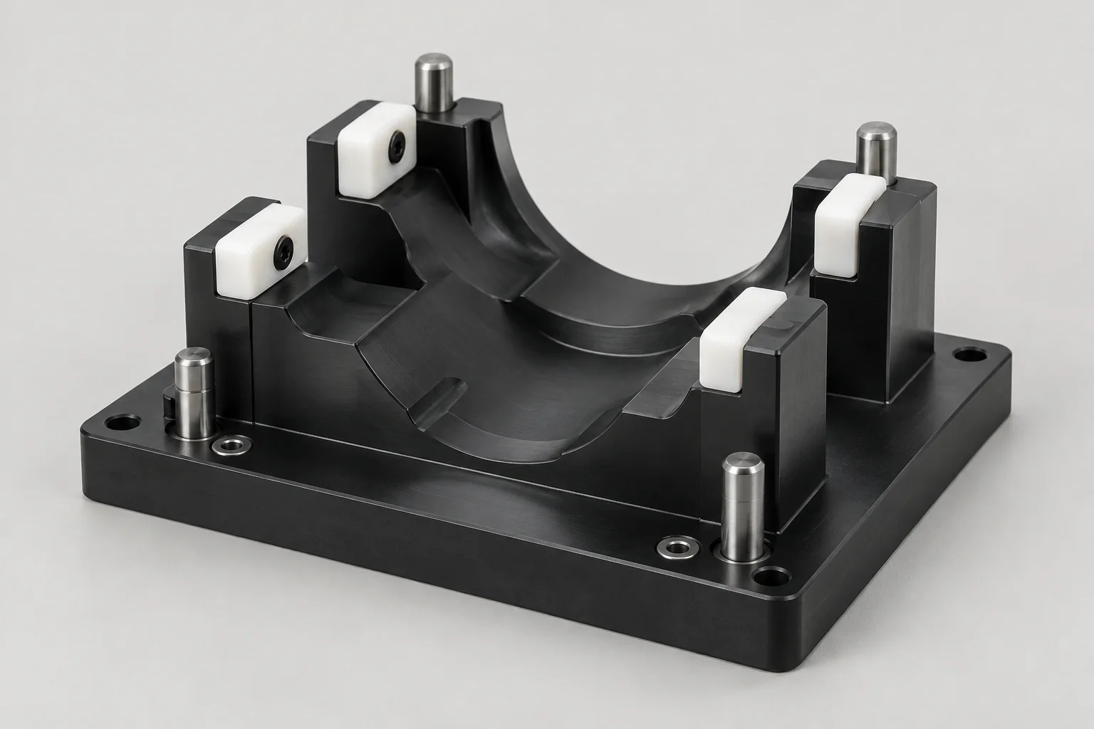
Production nests, assembly tooling and inspection fixtures with repeatable locating and replaceable contact features.
Explore component details →Machine type, component function and operating requirement determine where a polymer is useful.
Bushings, wear pads, guides, spacers and housings need precise machine fit, wear control and stable dimensions. Include coolant, chips and mounting loads.
Rollers, wear strips, chain guides, bearings and slide blocks manage repeated contact. Compare abrasion, friction, impact and noise across the operating cycle.
Gears, rollers, guides, bushings and fixtures operate through repeated cycles. Speed, repeatability and protection of the handled product are key inputs.
Manifolds, valve blocks, bushings, housings and sealing interfaces require media compatibility, pressure, fluid temperature and stable sealing geometry.
Liners, wear blocks, guide plates and rollers face impact or abrasive contamination. Plan thickness, support and practical replacement access.
Structural housings, brackets, spacers and custom components connect subassemblies. Define sustained loads, alignment, fasteners and the released assembly interfaces.
There is no single best plastic. POM is a candidate for precision machine parts, UHMW for conveyor wear surfaces, Nylon for tough loaded components and PEEK for demanding heat or chemicals.
| Material | Main advantage | Typical machinery use |
|---|---|---|
| POM / Delrin | Dimensional stability and useful low-friction behavior | Precision gears, guides and fixtures |
| Nylon | Toughness and wear performance | Bushings, rollers and loaded wear parts |
| UHMW-PE | Abrasion, impact and low-friction contact | Wear pads, guides and conveyor parts |
| PEEK | Temperature, strength and chemical performance | High-performance machine parts |
| PTFE | Low friction and broad chemical compatibility | Sliding, sealing and isolation parts |
| PPS | Thermal and chemical stability | Technical machinery components |
| PET-P | Low moisture uptake and dimensional stability | Precision mechanical parts |
| HDPE | Chemical resistance and economical stock | General machine components |
Compare the exact grade, stock form and supplier data under the relevant conditions. Fillers, conditioning and sustained loads can change the result. A useful room-temperature property does not establish the component’s operating limit or service life.
Sleeve bearings, flanged bushings, journal bearings, thrust components and guide sleeves support motion through a defined contact system.
Radial, axial and peak loads set contact pressure. Include impact, edge loading, supported area and any misalignment.
Sliding speed generates frictional heat. Supply shaft diameter, rotational speed or linear travel and motion type.
Hardness, coating, roughness and mating material influence wear. The same bushing can behave differently on another shaft.
Account for installed fit, thermal expansion, moisture where relevant and creep. An interference fit can change the running bore.
Dry, grease, oil or process-fluid conditions affect friction and temperature. Dry-running behavior requires a suitable grade and duty.
Select bearings and bushings using load, speed, shaft material, running clearance, temperature and lubrication together. Supplier pressure–velocity data can inform screening within its stated conditions; it is not a universal capacity for every geometry. Validate critical service with the intended shaft and operating cycle.
Conveyor and guide rollers, spur or helical gears, worm wheels, pulleys and appropriate sprocket-type components need matched geometry and duty.
Specify steady and peak torque, starts, reversals and speed. Load cycling and frictional heat can change tooth or hub performance.
Release tooth form, pitch or module, mating gear and center distance. Thermal movement and mounting stiffness affect engagement.
Control roller concentricity, shaft interfaces and retained bearings. Define the measurement references and installed condition.
Polymers may help reduce noise, weight or corrosion. Evaluate the pairing, lubrication and acceptable wear rather than assuming a quieter material will last longer.
Plastic transmission parts are attractive where lower noise, lower mass, corrosion resistance or reduced lubrication are valuable. Torque, speed, alignment and temperature still control suitability. Gear tooth geometry and load rating must be established for the intended design.
Wear strips, guide blocks, slide pads, chain guides, liner plates and V-guides provide replaceable contact between moving assemblies.
UHMW, Nylon, POM or PEEK suit different duties. Match the polymer to the mating material, finish, temperature and abrasive exposure.
Review contact area, support and movement. Local edge loads or trapped particles can dominate wear.
Provide wear allowance above fasteners and a supported residual section. Keep hardware below the replacement limit.
Define acceptable clearance change, minimum remaining thickness and inspection access. Use representative trials for demanding service.
Wear components should protect the machine’s more expensive structure. Material, thickness, fastener recess, counterface and replacement allowance belong in one design review. Low friction alone does not establish zero wear or a maintenance interval.
Polycarbonate guards, sensor housings, motor covers, machine enclosures, protective panels and insulating structures need defined mounting and operating requirements.
Specify required viewing area, impact exposure and surface condition. Material thickness alone does not establish machine-guard safety.
Control hole patterns, edge distances, supported spans and fastener pressure. Allow movement without losing alignment or retention.
Select a documented insulating grade where separation is needed. Conductive or ESD behavior is a different material requirement.
Include oils, coolant, cleaners, vapors and stressed mounting conditions. Check compatibility with the exact grade and service temperature.
The equipment designer must define the guard geometry, retention and applicable safety requirements. Machined panels and covers are supplied to that approved specification; complete machine safety or enclosure ratings require a separately defined evaluation.
Manifolds, valve blocks, pump housings, fittings, sealing interfaces and chemical distribution blocks connect process media to machined flow geometry.
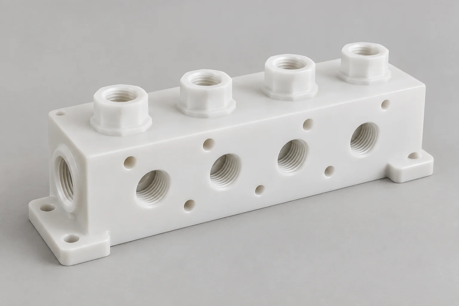
Identify every fluid, additive and cleaning agent. Compatibility can change with concentration, mixed media and exposure duration.
State continuous and peak conditions, pressure cycling and external loads. Generic chemical resistance does not establish a pressure rating.
Define seal type, grooves, mating surfaces, port threads and installation loads. Avoid treating tapered threads as a universal sealing solution.
PVDF, PTFE, PEEK, PVC, PP and PPS may be considered for different duties. Confirm the exact grade, stock availability and complete operating conditions.
Choose fluid-system material using media, concentration, temperature, pressure and sealing method together. Agree any leak or pressure testing, cleanliness and documentation before manufacture. A dimensionally correct manifold is not automatically a validated pressure assembly.
Assembly nests, drilling jigs, inspection fixtures, poka-yoke tooling, part locators and test tooling match the workpiece and production sequence.
Suitable contact pads can protect finished parts. Control debris, contact pressure and edge radii.
Polymer tooling can be easier to handle. Retain enough section and support for stiffness and repeatable positioning.
Insulating tooling can separate conductive parts. Specify a documented static-control grade where charge dissipation is needed instead.
Machine drawing-based nests and changeover features without mold tooling. Release the workpiece revision and loading method.
Use CAD to define shaped contact surfaces with relief for part variation, clamping and inspection access.
Separate locating features from replaceable wear contacts where practical. A fixture should locate the part consistently without distorting it; confirm clamping forces, datums and acceptable movement before release.
Life is determined by the complete operating system: load, speed, duty cycle, counterface, temperature, contamination and lubrication.
Contact stress changes with force, contact area and alignment. Include sustained loads and peaks.
Frictional heat increases with motion. Identify sliding, rotation, oscillation and reversals.
Continuous operation differs from intermittent use with cooling periods. Provide running hours, dwell and cycle frequency.
Roughness, hardness, coating and mating material affect friction and wear. Specify the actual machine surface.
Ambient and generated heat change stiffness, expansion and clearance. Use the relevant hot-spot conditions.
Dust, grit, chips or product debris can accelerate wear. Consider exclusion, cleaning and replacement access.
Specify allowable wear, clearance change and the desired inspection interval. Use grade data and representative machine trials to assess demanding duties. No single friction coefficient or material name guarantees unlimited life or maintenance-free operation.
Control fits, bores, sealing faces, locating features and wear surfaces tightly where function requires it. Avoid unnecessary tight tolerances on unrelated geometry.
| Feature | Why it matters |
|---|---|
| Bore diameter | Shaft and bearing fit |
| Hole position | Machine assembly and locating |
| Roller runout | Smooth operation and contact |
| Gear geometry | Motion transmission and backlash |
| Wear pad thickness | Running clearance and replacement allowance |
| Housing interface | Component alignment |
| Spacer thickness | Mechanical stack control |
| Flatness | Mounting stability |
| Datum relationship | Multi-part alignment |
Agree GD&T, temperature, conditioning and free or restrained inspection state. Plastic expansion, creep and moisture response differ from metals. Define the functional relationship and mating component rather than assigning one tight tolerance to every feature.
A plastic that works in dry room-temperature conditions may behave differently under heat, moisture, coolant or sustained load.
Heat changes stiffness, wear and thermal expansion. Include starts, stops, localized friction and peak exposure.
Nylon can absorb moisture and change dimensions. Specify conditioning, humidity or liquid exposure and the assembled clearance.
Coolants, cleaners, oils and process chemicals matter. Supply concentration, contact time, temperature and any mechanical stress.
Outdoor machinery adds sunlight, weather and temperature cycling. Review a suitable stabilized grade and the exposed component function.
Material suitability depends on the specific load, speed, temperature, environment and machine design. Food-contact, chemical and thermal requirements need exact grade documentation and applicable conditions; they cannot be inferred from a generic polymer name.
Build the functional duty and service access into the released design.
Identify radial, axial, sliding, torque and impact loads with the support and contact area.
Consider temperature, chemicals, moisture and wear together.
Allow for plastic expansion, moisture and creep. Check the installed rather than only free-state dimensions.
Make pads, guides and contact inserts accessible without replacing the expensive machine structure.
Use accessible functional references for inspection and repeat assembly.
Support thin sections and avoid unnecessary distortion from deep stock removal or clamping.
Sustained compression can cause creep. Review bearing area, washers, inserts and retention.
Prioritize fits and locating interfaces; leave practical limits on noncritical features.
Choose the route around rotational or prismatic geometry, material behavior and approved hardware.
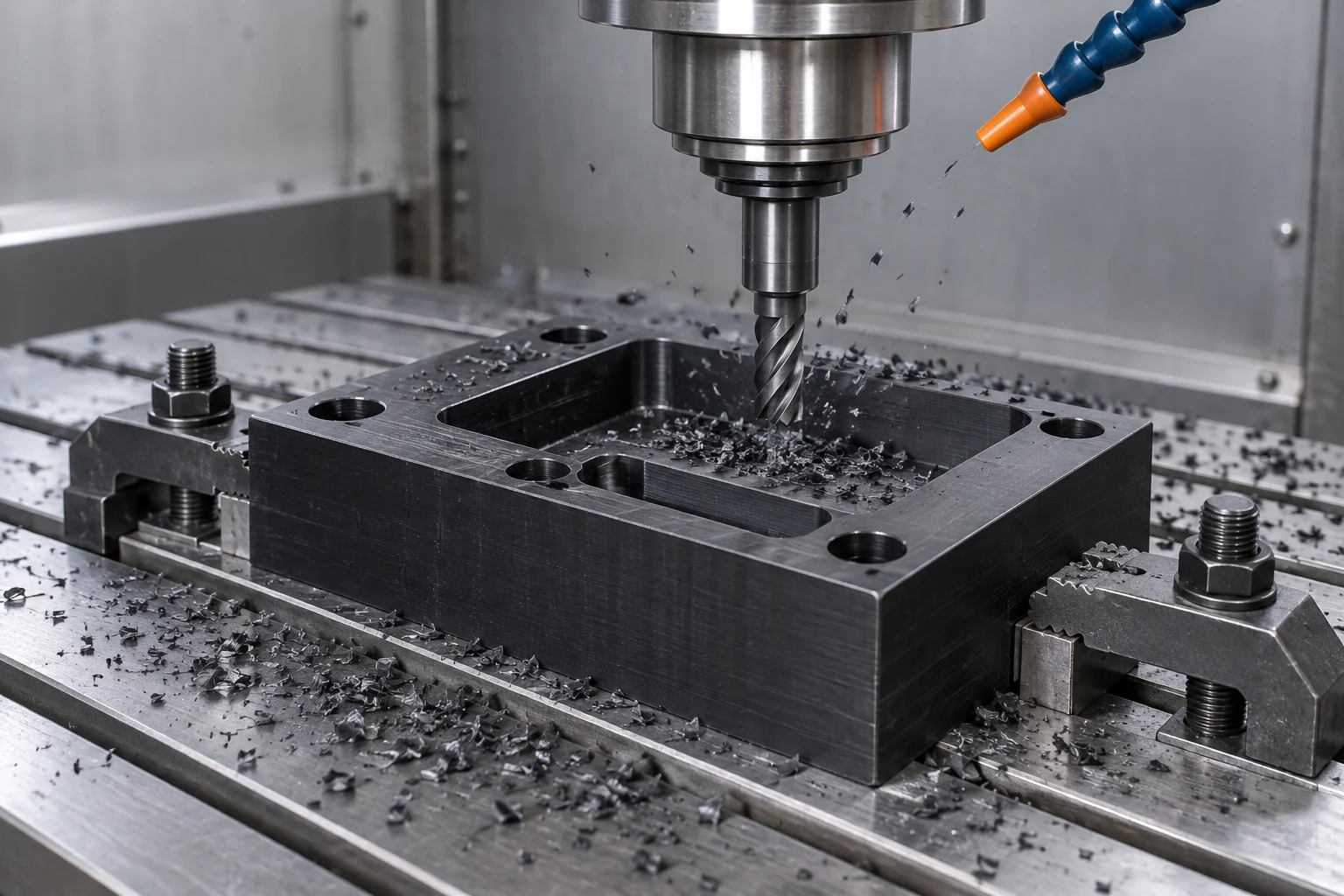
Machine housings, guides, wear blocks and fixtures with defined mounting faces and pockets.
Produce rollers, bushings, plain bearings and spacers around concentric functional interfaces.
Access complex multi-face components where geometry justifies the process.
Create mounting holes, threads and hardware interfaces to the released specification.
Install specified bearings, metal inserts, pins and fasteners under an agreed assembly scope.
Verify the drawing-defined functional features, fit and inspection state.
Yes, where the intended geometry can be established reliably. Drawings, CAD models, dimensioned sketches and physical samples can support replacement-part review.
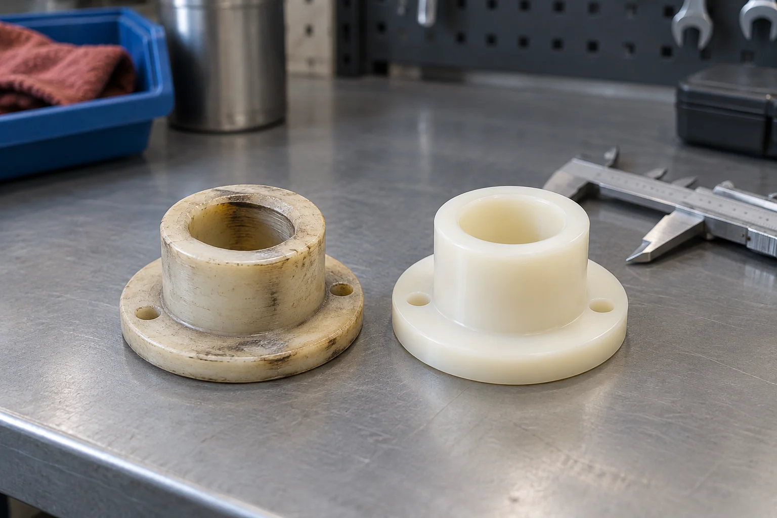
Obsolete bushings, discontinued wear pads, damaged rollers, old guide blocks, replacement spacers and legacy housings.
Use unworn areas, mating components and known machine clearances. Worn surfaces should not be copied blindly.
Confirm material, intended dimensions, fits and any design change before machining. A sample is evidence, not a complete released specification.
Check the first replacement in the machine, record approved geometry and preserve the revision for future maintenance orders.
A physical sample can help reconstruct geometry, but damage, swelling or wear may hide the original fit. Supply photos, mating dimensions, failure observations and the machine function. One-off quantities can be reviewed for feasibility and quotation; machine validation remains part of the agreed release process.
Define critical functional features, inspection methods and any fit checks before production.
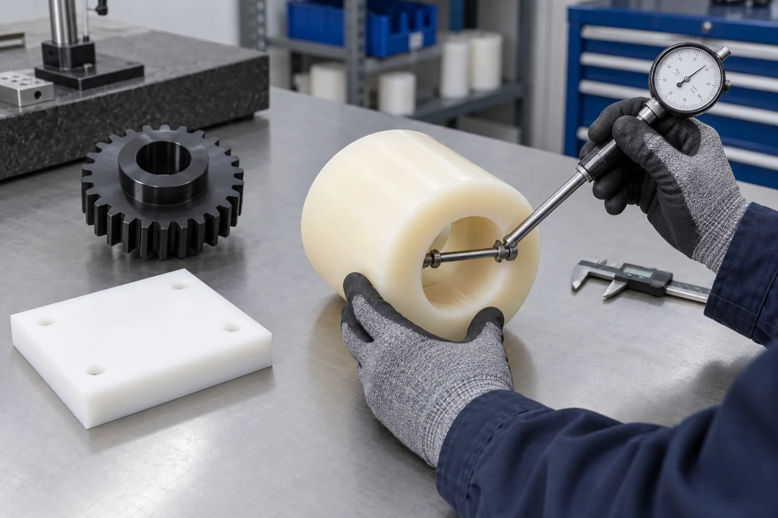
Confirm the specified grade and requested available supplier documentation.
Align the released revision, datums and reportable features.
Check shaft fits and mounting relationships in the agreed measurement state.
Verify wear allowance, rolling contact and mounting stability as specified.
Check the approved hardware, position and retained interfaces.
Use provided mating components or an approved sample where included in the scope.
Inspect edges, contact surfaces and accessible features for interfering defects.
Protect bores, locating surfaces and finished wear contacts for shipment.
Repeat OEM and maintenance orders require drawing revision control, material grade consistency, machining-program control and agreed inspection criteria. Retain the approved sample where applicable and record authorized changes rather than repeating undocumented alterations.
Maintenance replacement parts deserve the same controlled release process as new OEM machine components.
Validate fit, motion concept and material direction with representative mating parts.
Confirm running clearance, assembly and wear behavior under the intended duty.
Supply specialized machinery builds and scheduled spare-part requirements.
Maintain approved material, geometry, hardware and inspection criteria for recurring orders.
Review load, speed, wear, friction, temperature, chemicals, moisture, mating materials and replacement requirements together before production.
Bearings, bushings, rollers, gears, wear pads, housings and production fixtures.
POM, Nylon, UHMW, PEEK, PTFE, PPS and other customer-specified grades.
Processes for both prismatic and rotational machine components.
Review drawings, CAD and existing samples to establish a manufacturable specification.
Machine development, OEM production and maintenance spares with controlled revisions.
Agree critical dimensions and acceptance requirements for the defined component scope.
Move from application requirements to the detailed product page for geometry, interfaces and drawing preparation.
Direct answers about wear materials, metal replacement, machine spares, tolerances and quotation.
POM, Nylon, UHMW, PEEK, PTFE, PPS, PET-P and HDPE are candidates for different functions. Select the grade for load, speed, wear, environment and dimensional requirements.
There is no universal best material. UHMW is often considered for abrasion and conveyor contact, Nylon for tough loaded wear parts and POM for precision interfaces; heat or chemicals may justify PEEK.
Yes, UHMW is often considered for low-friction guides and wear pads. Lower stiffness, creep and thermal movement must be considered in support and clearance.
Consider Nylon where toughness, impact and load conditions favor it. Review moisture-driven dimensional changes against POM and the actual assembled fit.
In some applications. Compare load, speed, shaft, temperature, clearance and lubrication; a polymer replacement may require revised geometry and validation.
Yes, suitable designs can use plastic gears. Torque, speed, tooth geometry, alignment, heat and lubrication determine their operating suitability.
Yes, where intended geometry can be reliably established from drawings, CAD, sketches or samples. Correct worn surfaces to approved dimensions before manufacture.
Control shaft fits, bores, runout, locating features, sealing faces and wear thickness. Define realistic limits and the inspection state for the material and geometry.
One-off replacements can be reviewed for machining feasibility and quotation. Supply the sample or drawing, intended dimensions, material and operating requirements.
Provide drawing or sample information, exact material, quantity, machine type, load, speed, counterface, lubrication, temperature, wear allowance and critical tolerances.
MACHINE DUTY. WEAR LIMIT. REPLACEMENT PLAN.
Upload your component drawing, CAD model or sample information and specify the material, quantity, machine type, load, speed, mating components, operating temperature, chemical exposure and critical tolerances. TOPS Plastics can review the geometry, material and machining approach before quotation.
Company, name, email and phone are required. Country, part number, quantity and drawing upload are optional. Include technical requirements in the drawing or email; combine CAD and supporting files into one ZIP if useful.
info@tops-precision.comSTEP / STP / IGES / X_T / DWG / DXF / PDF or ZIP, maximum 10 MB. Larger packages can be shared by email. Agree confidential-file handling before sending sensitive drawings.