01
Plastic Plain Bearings
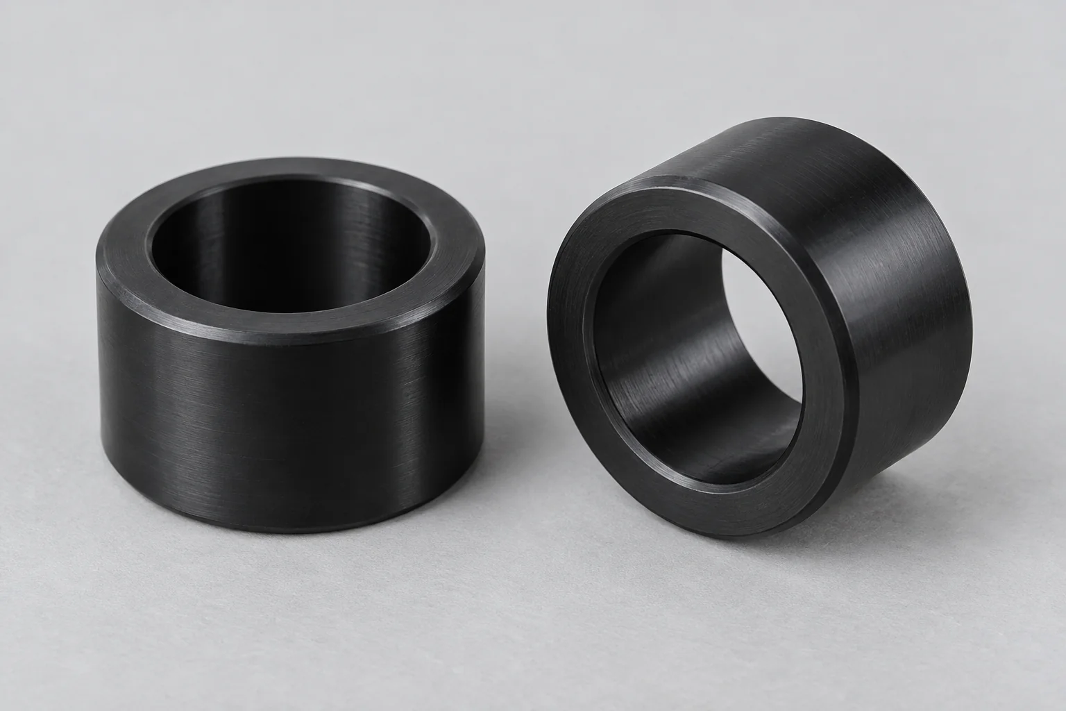
Sliding bearings for rotational or oscillating motion in shafts, pivots, guide mechanisms and industrial equipment.
Discuss this bearing →
SPECIFIED FOR THE MOTION SYSTEM
TOPS Plastics manufactures custom plastic bearings and precision sliding-bearing components for industrial machinery, automation, robotics, semiconductor equipment, medical equipment and OEM applications. We produce plain bearings, flanged bearings, sleeve bearings, thrust components and special bearing geometries from POM/Delrin, Nylon, PEEK, PTFE, UHMW and other engineering plastics according to customer drawings and operating requirements.
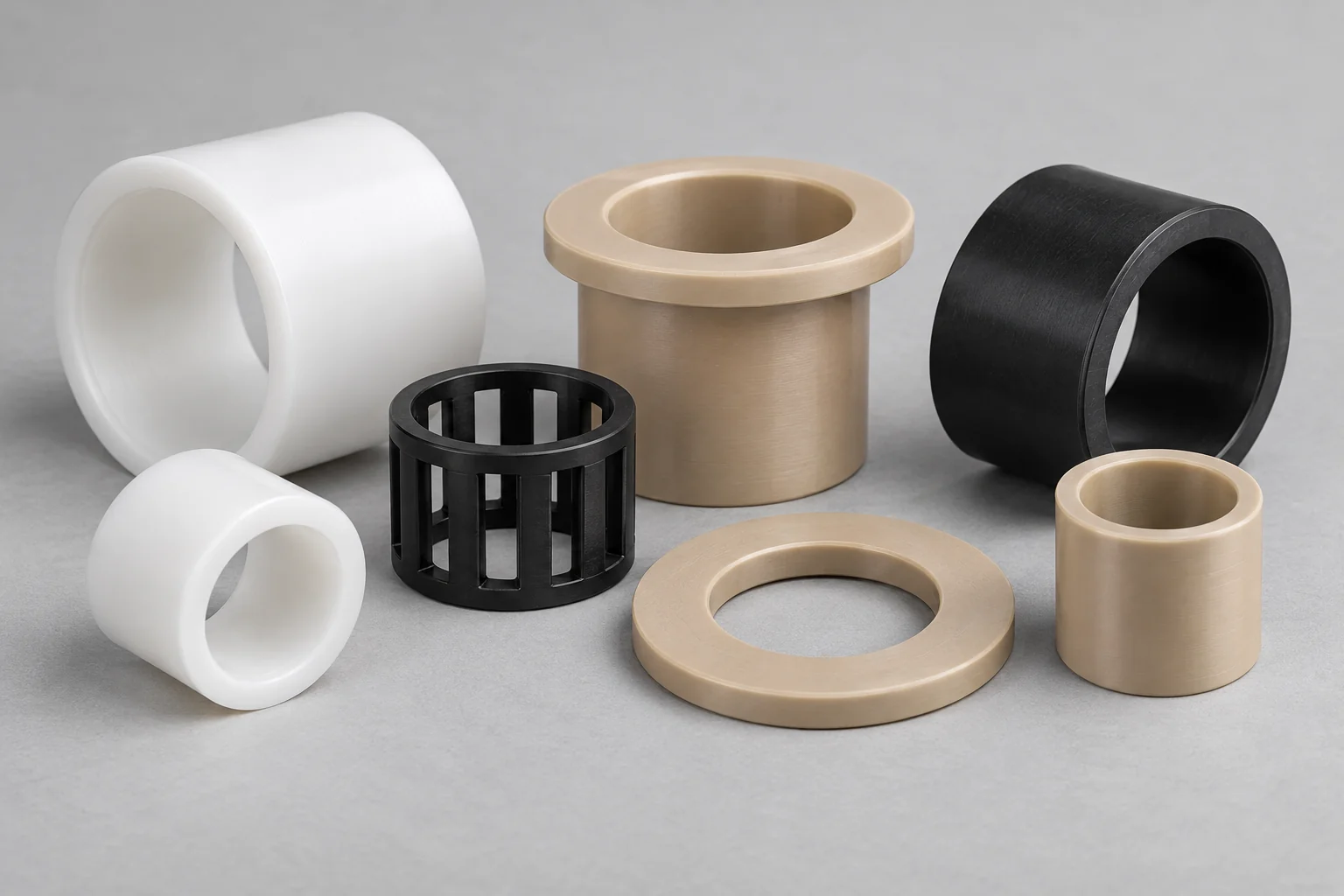
A bearing quotation starts with the motion system: the polymer, mating shaft, housing, working clearance and operating duty.
| Capability | TOPS Plastics |
|---|---|
| Bearing types | Plain, sleeve, flanged, thrust, journal, rings, cages and special drawing-based components. |
| Materials | POM / Delrin, Nylon, PTFE, PEEK, UHMW and specified engineering or filled bearing grades. |
| Geometry | Custom ID, OD, length, flange, grooves, shoulders and thrust faces. |
| Shaft interfaces | Plain bores, precision bores and special drawing-defined fits. |
| Housing interfaces | Slip, locating or press fits where the material and assembly justify them. |
| Processes | CNC turning, precision boring, secondary milling and drilling. |
| Production | Prototype, low-volume and repeat OEM orders. |
| Inspection | ID, OD, roundness, drawing-defined runout or coaxial relationship, width and functional dimensions. |
| Input | CAD models, 2D drawings and reference samples; agree a restored drawing when a sample is worn. |
Explore the bearing geometry that matches your machine. Each component is reviewed against its load direction, shaft, housing and duty.
Sliding bearings for rotational or oscillating motion in shafts, pivots, guide mechanisms and industrial equipment.
Discuss this bearing →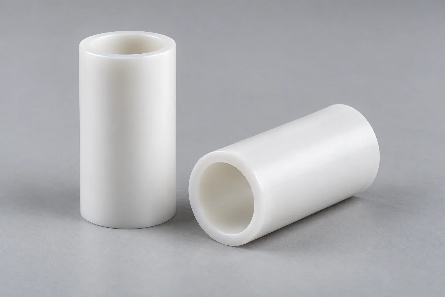
Cylindrical sliding bearings for shaft guidance and support, with custom length, bore and housing interface.
Discuss this bearing →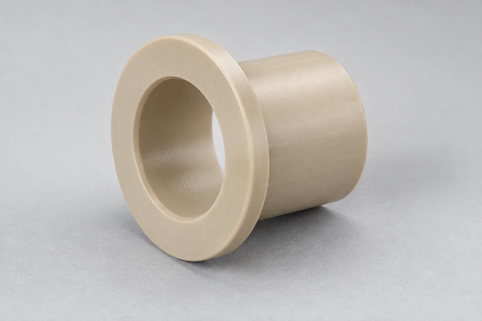
An integrated flange provides axial location and, where designed for it, thrust support.
Discuss this bearing →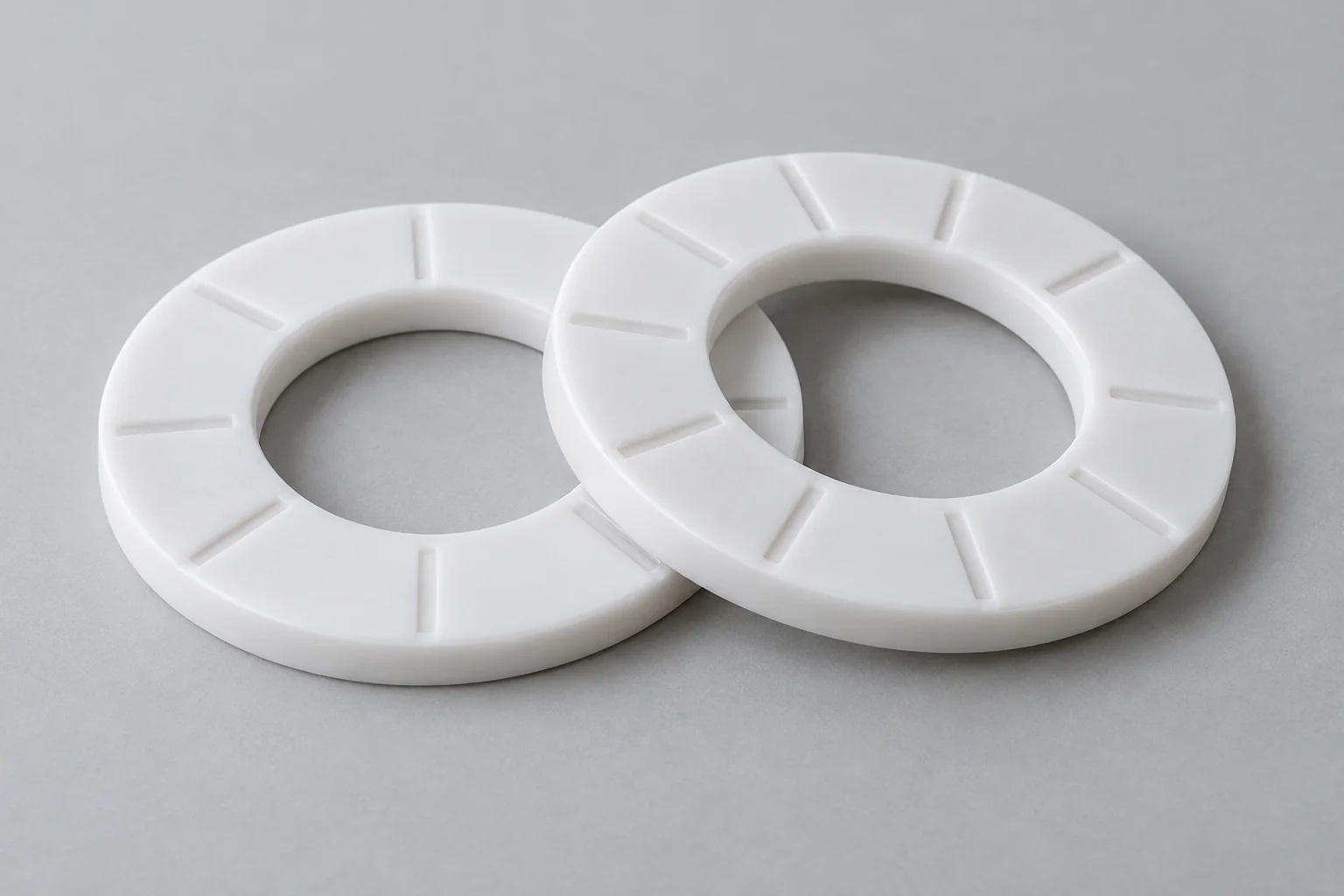
Annular sliding faces support axial load; define effective area, mating face and lubrication.
Discuss this bearing →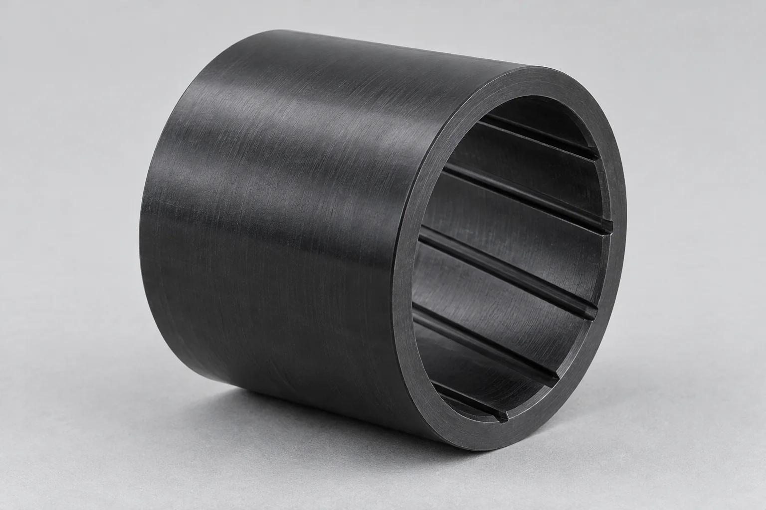
Sliding contact supports a rotating shaft. Review pressure, speed, shaft finish and running clearance.
Discuss this bearing →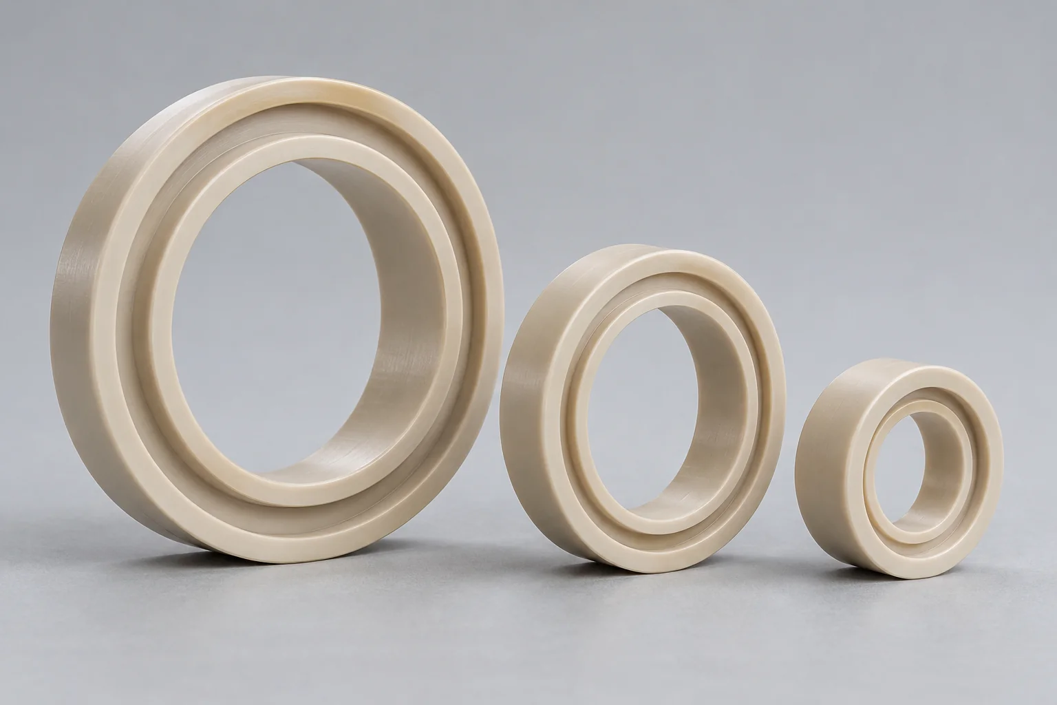
Custom inner or outer rings and wear interfaces machined to the mating geometry; assembly function remains drawing-specific.
Discuss this bearing →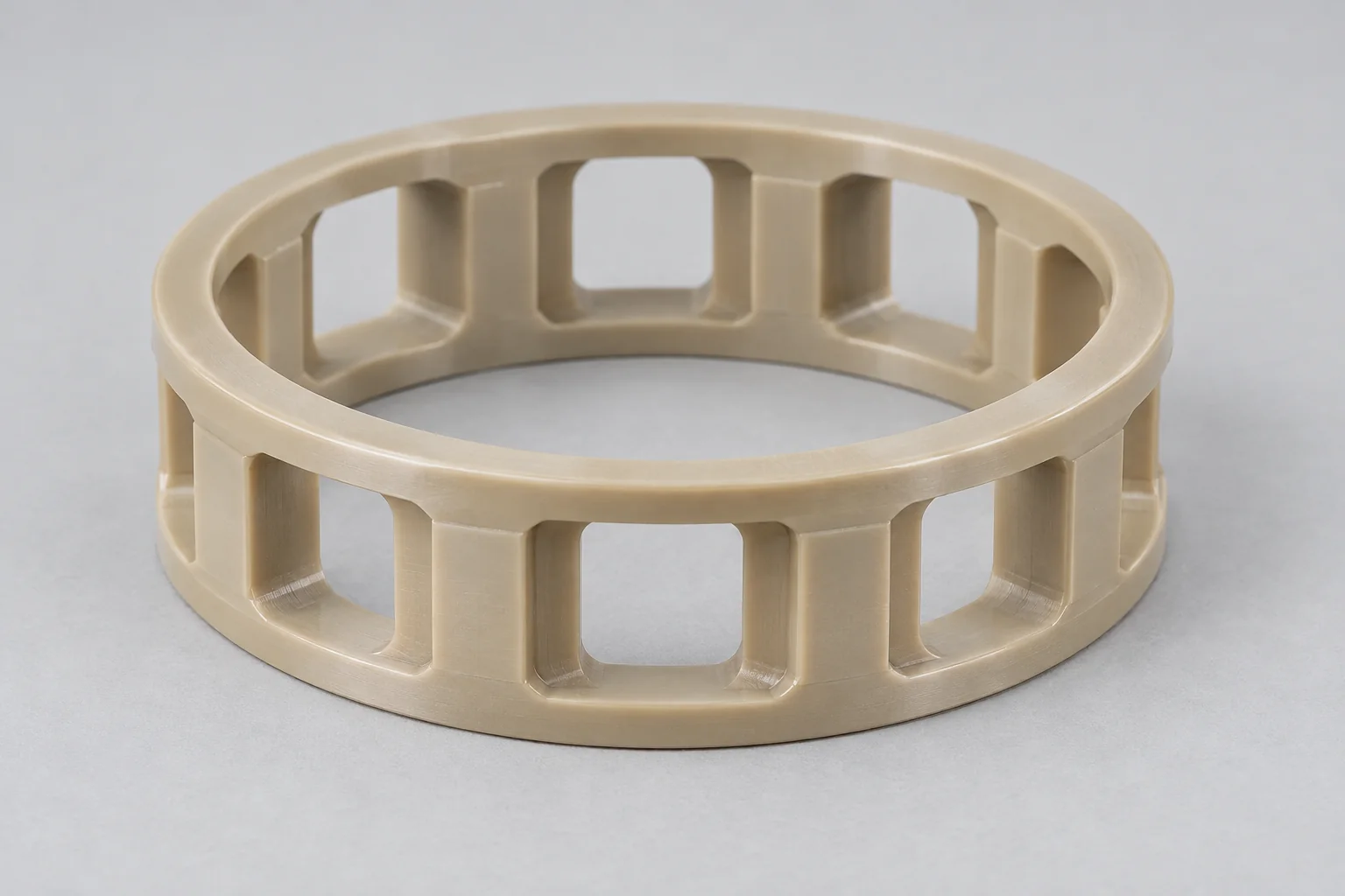
Polymer cages separate and guide rolling elements within a specified bearing assembly. Pocket geometry and assembly details are required.
Discuss this bearing →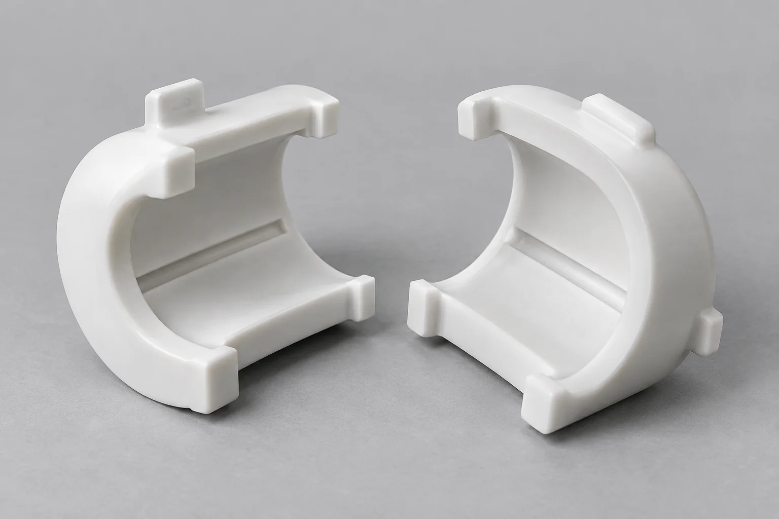
Shoulders, grooves, anti-rotation features, integrated flanges and nonstandard or split profiles made to the agreed drawing.
Discuss this bearing →Plastic bearings are polymer components that support, guide or separate moving machine elements while controlling friction and wear.
They may act as sliding sleeves, thrust surfaces, journal bearings or parts within a more complex bearing assembly. Many plastic plain bearings use sliding contact between the polymer and a mating shaft, rather than rolling elements.
This page focuses on custom machined sliding bearings and bearing components. A polymer cage or ring is one component of an assembly; it does not by itself constitute a complete rolling-element bearing. Self-aligning geometry can be reviewed from a defined drawing and mating assembly.
A plastic bushing is often a type of plain bearing. Plastic bearings describe a broader functional category that also includes thrust, journal and special configurations.
| Factor | Plastic bearings | Plastic bushings |
|---|---|---|
| Main concept | Functional bearing category. | Common cylindrical bearing geometry. |
| Geometry | Plain, sleeve, flanged, thrust, ring, cage and special components. | Usually cylindrical sleeve or flanged shapes. |
| Load | Radial, axial or combined, depending on design. | Often radial shaft support; a flange may also carry specified thrust. |
| Motion | Rotating, oscillating or sliding motion. | Often shaft guidance and pivot motion. |
| Design scope | Whole bearing function and its mating interfaces. | A narrower geometry and fit specification. |
| Relationship | Can include bushings and other bearing components. | A bushing can function as a plain bearing. |
For cylindrical sleeve and flanged bushing geometry, also see our Plastic Bushings page. Here, selection starts with bearing duty, friction, wear and the installed motion system.
Engineering polymers offer useful options when the complete operating conditions support them.
Selected polymers suit wet or chemically exposed service. Check the actual medium, concentration and temperature.
A polymer component can reduce assembly mass compared with an equivalent metal geometry.
Suitable sliding interfaces can reduce contact noise. Shaft finish, alignment and mounting still affect the result.
Bearing grades can provide favorable sliding behavior. Friction depends on grade, shaft, load, speed and lubrication.
Unfilled insulating grades can separate electrical paths. Conductive and carbon-filled grades require separate review.
CNC manufacture supports nonstandard geometry, prototypes and smaller recurring orders without dedicated molding tools.
POM is often considered for dimensional control, Nylon for tough wear service, PTFE for low friction and chemical exposure, and PEEK for demanding thermal or mechanical conditions.
| Material | Main strength | Main concern | Typical use |
|---|---|---|---|
| POM / Delrin | Low moisture uptake, machinability and dimensional stability. | Grade-specific temperature and chemical limits. | Precision plain bearings. |
| Nylon | Toughness and useful wear behavior. | Moisture uptake changes dimensions and clearance. | Industrial load-bearing parts. |
| PTFE | Very low friction and broad chemical resistance. | Creep and low stiffness, especially under sustained load. | Chemical-service and low-friction interfaces. |
| PEEK | Strength and heat capability in suitable grades. | Cost; grade and shaft compatibility still matter. | Demanding technical bearings. |
| UHMW | Abrasion resistance and impact toughness. | Low rigidity, creep and limited temperature capability. | Wear-heavy, lower-load applications. |
| PET-P | Dimensional stability and low moisture uptake. | Notch sensitivity and toughness need review. | Precision mechanical bearings. |
| PPS | Chemical and thermal stability. | Brittleness and filler effects. | Technical bearings in demanding environments. |
| Filled bearing grades | Application-specific friction, wear or creep behavior. | Filler effects on shaft wear, insulation and compliance. | Specialized motion systems. |
Self-lubricating and maintenance-free are grade- and application-specific descriptions. They are not universal properties of POM, Nylon, PTFE or other machined plastics. Select the exact supplier grade and validate the mating pair.
Load and speed must be reviewed together with temperature, the shaft surface and the lubrication regime. Dimensions alone do not predict service life.
F: radial load · d: shaft diameter · L: bearing length
p: projected pressure · v: sliding velocity
Simple radial sleeve screening relationships. Actual contact, alignment, heat and grade data must be reviewed.
Higher radial or axial load increases contact pressure. The projected-area estimate applies to a simple radial sleeve; thrust faces require their own effective contact-area review. Edge loading and misalignment can increase local stress.
Increasing relative sliding velocity can increase frictional heat. Give shaft speed, diameter, oscillation angle or linear speed and the duty cycle. Start-stop and peak conditions matter.
PV is a screening parameter for sliding duty. Permissible values depend on grade, temperature, shaft surface, lubrication, duty cycle and cooling; no universal polymer PV limit is offered.
The coefficient depends on the polymer and counterface pair as well as load, speed, temperature and lubrication. Static starting friction may differ from running friction.
Service life depends on the polymer, shaft condition, contamination, alignment and acceptable wear. A trial or application-specific test may be needed before fixing a replacement interval.
Use consistent units: F in N and d and L in mm give p in N/mm² (MPa). With v in m/s, PV is in MPa·m/s. These screening relationships are not a life calculation, a guaranteed rating or a substitute for the selected grade’s test data.
Specify the shaft, housing and installed bearing as one tolerance system. Retention and running clearance solve different problems.
Diametral clearance = installed bore − shaft diameter
The actual shaft diameter and its tolerance establish working clearance with the bearing bore. Provide shaft material, hardness and surface finish as well as size.
The bore controls bearing retention and installed geometry. Housing material, stiffness, wall thickness and temperature affect the fit.
Allow for thermal expansion, moisture uptake, elastic deformation, creep and shaft tolerances. Too little clearance can cause binding; excessive clearance affects guidance and vibration.
A press fit can change the bore, especially in a thin wall. Define whether acceptance applies before installation, in a reference housing or in the finished assembly.
Diametral running clearance is the installed bearing bore minus the actual shaft diameter at the stated condition. For a centered circular pair, nominal radial clearance is half the diametral clearance. Review the tolerance extremes and operating condition rather than assigning one clearance to every material.
Share both the bearing drawing and the mating geometry so that machined features have a clear function.
| Parameter | Customization and review |
|---|---|
| Inner diameter | Drawing-based bore, tolerance and installed inspection state. |
| Outer diameter | Housing retention or locating fit. |
| Bearing length | Contact length, alignment and load distribution. |
| Flange diameter | Housing seating and axial location. |
| Flange thickness | Axial stack-up and stiffness. |
| Thrust face | Axial contact area, finish and flatness requirements. |
| Lubrication grooves | Profile and position for the specified lubrication regime. |
| Retention grooves | Drawing-based groove and retaining component. |
| Chamfers | Assembly lead-ins and edge protection. |
| Shoulders | Axial seating and assembly location. |
| Anti-rotation features | Flats, keys, tabs or cross features where specified. |
| Split geometry | Where assembly access, support and material justify it. |
| Special profiles | Nonstandard or self-aligning profiles reviewed with mating parts. |
Specify the operating range and exposure history, including cleaning, storage and start-up conditions.
Stiffness and allowable loading change with temperature. Include continuous, peak and inspection temperatures, heat generation and the surrounding cooling conditions.
Nylon can change dimensions with humidity or immersion. Agree conditioning and account for the installed clearance across the intended environment.
Review the actual chemical, concentration, temperature, exposure time and stress. A generic resistance label does not establish application compatibility.
Some bearing systems tolerate dirty service, but abrasive particles can damage the shaft and polymer. Consider debris, wiping, sealing and maintenance access.
Installed bore, roundness, the ID-to-OD relationship and housing fit often matter more than tightening every external dimension.
| Feature | Why it matters |
|---|---|
| Inner diameter | Controls the running clearance in the specified installed or free state. |
| Outer diameter | Defines housing fit and retention. |
| Roundness | Affects contact uniformity and local pressure. |
| ID-to-OD coaxial relationship | Relates shaft support to housing location; specify the actual datum and GD&T requirement. |
| Flange thickness | Controls axial positioning and stack-up. |
| Face perpendicularity | Affects seating and thrust-face contact. |
| Bearing length | Influences load distribution and alignment sensitivity. |
| Thrust surface | Supports axial load; define flatness, finish and location. |
| Groove location | Controls lubrication distribution or retention. |
Specify concentricity, runout or another geometric control only where appropriate to the drawing standard and function; these are not interchangeable. Agree inspection temperature, conditioning, gauge contact force, datum setup and assembly state. No blanket tolerance is promised for all bearing grades and sizes.
The most useful drawing identifies the functional interfaces and the conditions in which they must work.
Identify radial or axial loading and whether the motion rotates, oscillates or slides. Include load direction and any shock.
Give material, hardness, diameter tolerance and surface finish. A surface that suits one grade may not suit another.
Account for thermal change, moisture, tolerances and installed deformation over the operating range.
Compression can reduce the working bore and overstress thin walls. Review retention without automatically copying a metal-bearing fit.
A longer bearing provides projected area but can be more sensitive to shaft misalignment and edge loading.
Sustained load and elevated temperature can change the geometry over time. Separate short-term fit from long-term retention.
Review material-grade test data, actual duty and shaft compatibility alongside cost and machinability.
State dry running, grease, oil or process-fluid exposure. Confirm lubricant compatibility and access for replenishment if required.
The machining sequence follows the functional bore, outer diameter, seating faces and secondary features.
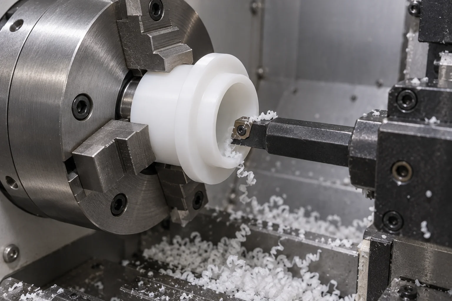
Produces OD, ID, flanges, shoulders and thrust surfaces from suitable stock with controlled support and cutting conditions.
Finishes critical shaft interfaces. Measurement and release conditions are planned with material response and installation in mind.
Adds grooves, flats, cross holes and anti-rotation features where tool access and wall stiffness permit.
Removes unwanted burrs and protects bearing edges and mating features. Sliding surfaces follow the specified finish requirement.
Checks bore, OD, roundness, coaxial relationship and flange geometry to the agreed drawing and method.
Choose by the motion system and bearing type. A sliding polymer component is not an automatic substitute for a metal rolling-element assembly.
| Factor | Plastic bearings | Metal bearings |
|---|---|---|
| Weight | Typically lower for comparable geometry. | Typically higher; alloy and geometry matter. |
| Corrosion | Strong options, depending on polymer and medium. | Depends on alloy, coating and exposure. |
| Electrical isolation | Available in suitable insulating grades; filled grades vary. | Usually conductive. |
| Noise | Sliding polymer contact can reduce contact noise. | Depends on bearing type, lubrication and mounting. |
| High load | Limited by stiffness, temperature and creep. | Often supports higher loads, depending on design. |
| Heat dissipation | Generally lower thermal conductivity. | Generally better heat conduction. |
| Dimensional stability | More sensitive to temperature, moisture and sustained load. | Often more dimensionally rigid. |
| Chemical exposure | Useful options with grade-specific checks. | Alloy and medium must be matched. |
Consider plastic where low weight, corrosion resistance, electrical isolation or quiet sliding contact matters. Consider metal where high load, stiffness or heat conduction dominates. Validate a substitution in the actual assembly.
Application examples guide the discussion; material suitability and any regulatory documentation must be confirmed for the specific project.
| Industry | Typical bearing application |
|---|---|
| Industrial Machinery | Shaft support, pivots and sliding mechanisms. |
| Automation & Robotics | Low-friction joints and guide interfaces. |
| Packaging | Conveyor pivots and recurring motion systems. |
| Food Equipment | Corrosion-resistant mechanisms with suitable, documented grades and cleaning compatibility. |
| Medical Equipment | Quiet mechanical movement with application-specific material review. |
| Electronics | Insulating motion components where the grade supports isolation. |
| Chemical Processing | Chemical-resistant shaft support matched to the medium. |
| Marine | Corrosion-resistant motion components with water exposure and load review. |
Inspection must state whether the bearing is free, installed in a reference housing or assembled in the final mechanism.
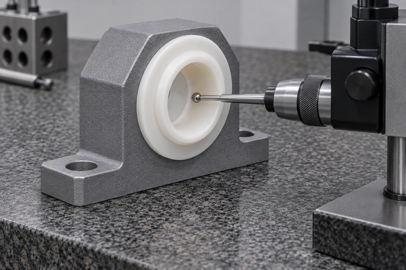
Confirm the specified polymer and any filler or supplier designation against the agreed order documentation.
Identify shaft and housing interfaces, datums, working clearance and the acceptance state.
Use suitable measurement methods and contact force for the material, wall thickness and required tolerance.
Check the drawing-defined form and positional requirements with the agreed setup; do not infer them from one diameter reading.
Verify seating geometry, width and the specified thrust-face features.
Document the reference housing size, assembly procedure and conditioning where installed bore is controlled.
Check sliding surfaces, grooves, lead-ins and edges for the specified finish and unwanted burrs.
Protect functional surfaces, identify revisions and keep inspection records as agreed.
Use the prototype to establish functional acceptance before repeating the machining specification.
Validate shaft fit, friction, grade and running clearance in the intended assembly. Confirm the test duty and acceptable wear.
CNC manufacture supports specialized OEM equipment and smaller orders with drawing-based geometry.
Control material grade, drawing revision, machining program and inspection method so recurring orders follow the approved specification.
A plastic bearing must be designed as part of the motion system. Material, shaft, housing, clearance, load, speed, temperature and environment determine performance—not the bearing dimensions alone.
Custom geometry reviewed against your CAD model and functional drawing.
Machining routes centered on the bore, OD and seating surfaces.
Engineering plastics considered against the environment and duty.
Both mating interfaces considered in the specification.
Free and installed dimensions distinguished before production.
Sleeves, flanges and thrust faces reviewed for their load direction.
A defined path from initial fit validation to recurring production.
Acceptance methods and measurement conditions agreed with the drawing.
Practical answers for specifying, selecting and sourcing custom polymer bearings.
Plastic bearings support or guide moving parts while controlling friction and wear. Common duties include shaft support, pivots, sliding guides and thrust interfaces in industrial equipment.
A plastic bushing is often a cylindrical plain bearing. Plastic bearings are the broader functional category and can include sleeve, flanged, thrust, journal and other bearing components.
There is no single best plastic for every bearing. POM, Nylon, PTFE and PEEK offer different combinations of stability, toughness, friction and thermal capability; select the exact grade against load, speed, shaft and environment.
Neither is universally better. POM is often considered for low moisture uptake and dimensional control, while Nylon offers toughness and useful wear behavior. Moisture, temperature, grade and the mating shaft decide suitability.
Some PTFE bearing systems can operate dry within their validated duty. Low friction alone does not guarantee adequate load capacity or life; review creep, grade, shaft finish, pressure, speed and temperature before specifying dry running.
Diametral clearance is the installed bore minus the shaft diameter at the specified condition. Review worst-case tolerances, press-fit bore change, thermal expansion, moisture and load deformation; there is no universal clearance allowance for all polymers.
PV is pressure multiplied by sliding velocity, used to screen sliding-bearing duty. Acceptable PV depends on the exact grade and test conditions, including shaft surface, lubrication, temperature, duty cycle and cooling. It does not independently predict service life.
Yes, where the grade and geometry support that assembly method. Specify the housing bore and material, wall thickness, retention and installed bore. Excessive interference can reduce clearance and distort the bearing.
Installed bore, housing fit, roundness, the ID-to-OD relationship and seating geometry are often the main functional controls. State the datums, GD&T, inspection temperature, conditioning and whether acceptance is free-state or installed.
Yes, we can review custom bearing drawings and CAD models for manufacture. Include the exact grade, mating shaft and housing, load, speed, lubrication, temperature and critical acceptance requirements with your request.
SHAFT. HOUSING. DUTY.
Upload your bearing drawing or CAD model and provide the material, bearing type, shaft diameter, housing bore, load, speed, running clearance and operating environment. TOPS Plastics can review the geometry, material selection and machining requirements before quotation.
Company, name, email and phone are required. Country, part number, quantity and drawing upload are optional. Include engineering details in your drawing package or email; the form stays short.
info@tops-precision.comSTEP / STP / IGES / X_T / DWG / DXF / PDF or ZIP, maximum 10 MB. Larger packages can be shared by email. Agree confidential-file handling before sending sensitive drawings.