01
Round Plastic Spacers
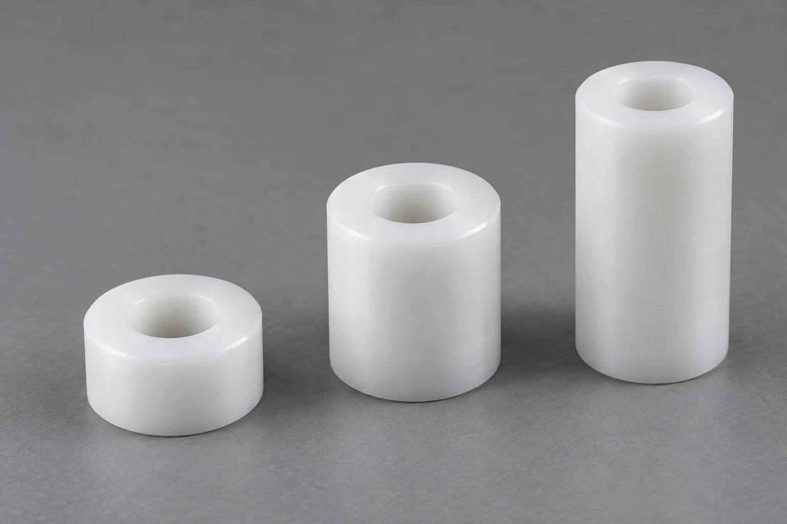
Short cylindrical distance pieces specified by OD, ID, length or thickness and chamfer.
Discuss this spacer →
THE DISTANCE THAT MAKES THE ASSEMBLY WORK
TOPS Plastics manufactures custom plastic spacers for industrial machinery, electronics, automation, semiconductor equipment, medical equipment and OEM assemblies. We produce round spacers, sleeve spacers, shoulder spacers, flanged spacers, threaded spacers and special-profile components from engineering plastics according to customer drawings and CAD models.
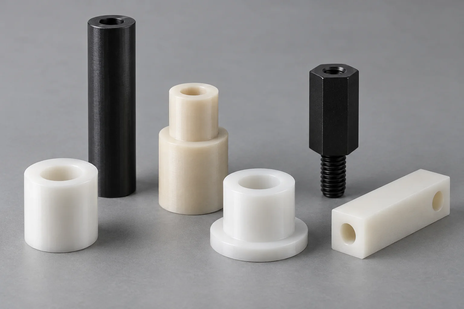
Custom-to-print spacing components are reviewed against their mating faces, fastener stack, environment and functional dimensions.
| Capability | TOPS Plastics |
|---|---|
| Spacer types | Round, sleeve, shoulder, flanged, washer, threaded, block and special profiles. |
| Materials | POM / Delrin, Nylon, PTFE, PEEK, PVC, Polycarbonate and specified engineering grades. |
| Geometry | Custom OD, ID, length, flange, shoulder and thread geometry. |
| Features | Chamfers, counterbores, countersinks, slots, flats, cross holes and offset holes. |
| Processes | CNC turning, boring, milling, drilling and tapping. |
| Production | Prototype, low-volume and repeat OEM production. |
| Input | CAD models, 2D drawings and reference samples; worn samples require dimensional agreement. |
| Inspection | Length, thickness, ID, OD, flatness and drawing-defined seating geometry. |
Explore the spacer geometry that matches your machine. Each component is reviewed against its seating faces, fastener, stack height and duty.
Short cylindrical distance pieces specified by OD, ID, length or thickness and chamfer.
Discuss this spacer →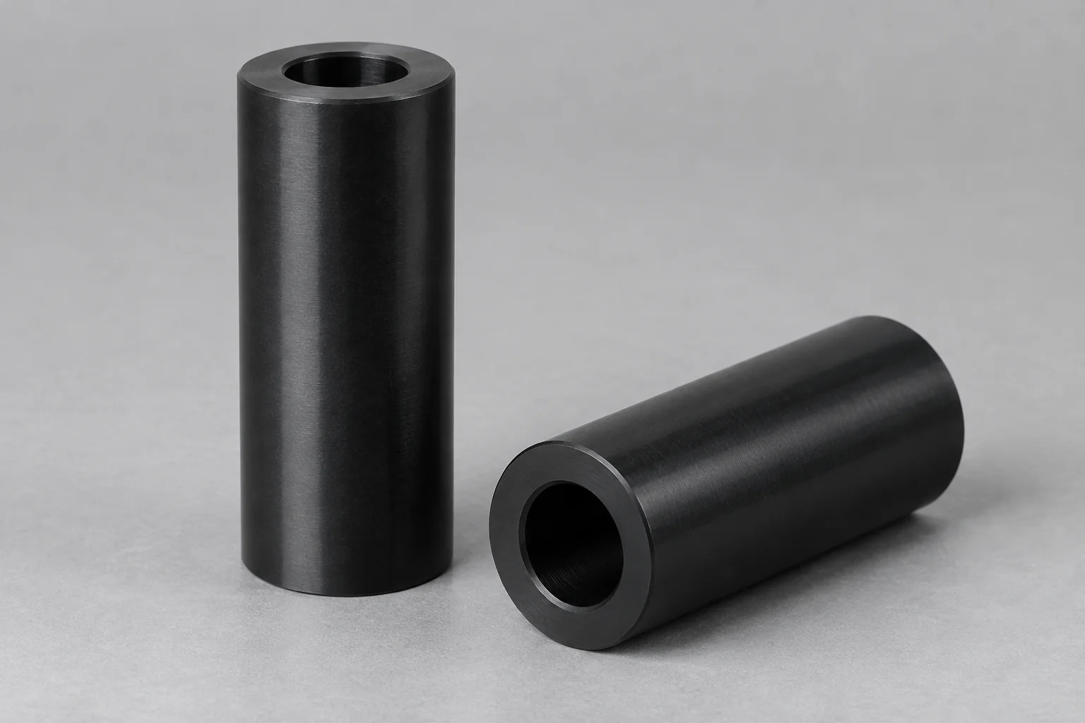
Longer cylindrical spacers that fit over a fastener, pin or shaft to maintain the required distance.
Discuss this spacer →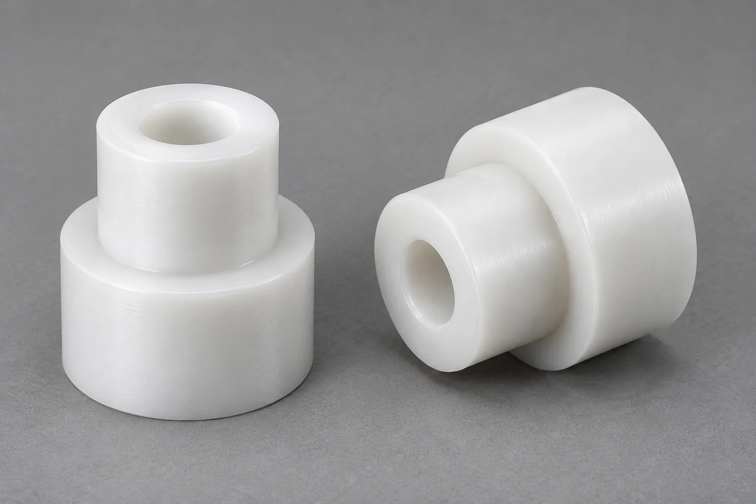
Stepped, multi-diameter geometry for location, isolation and controlled seating.
Discuss this spacer →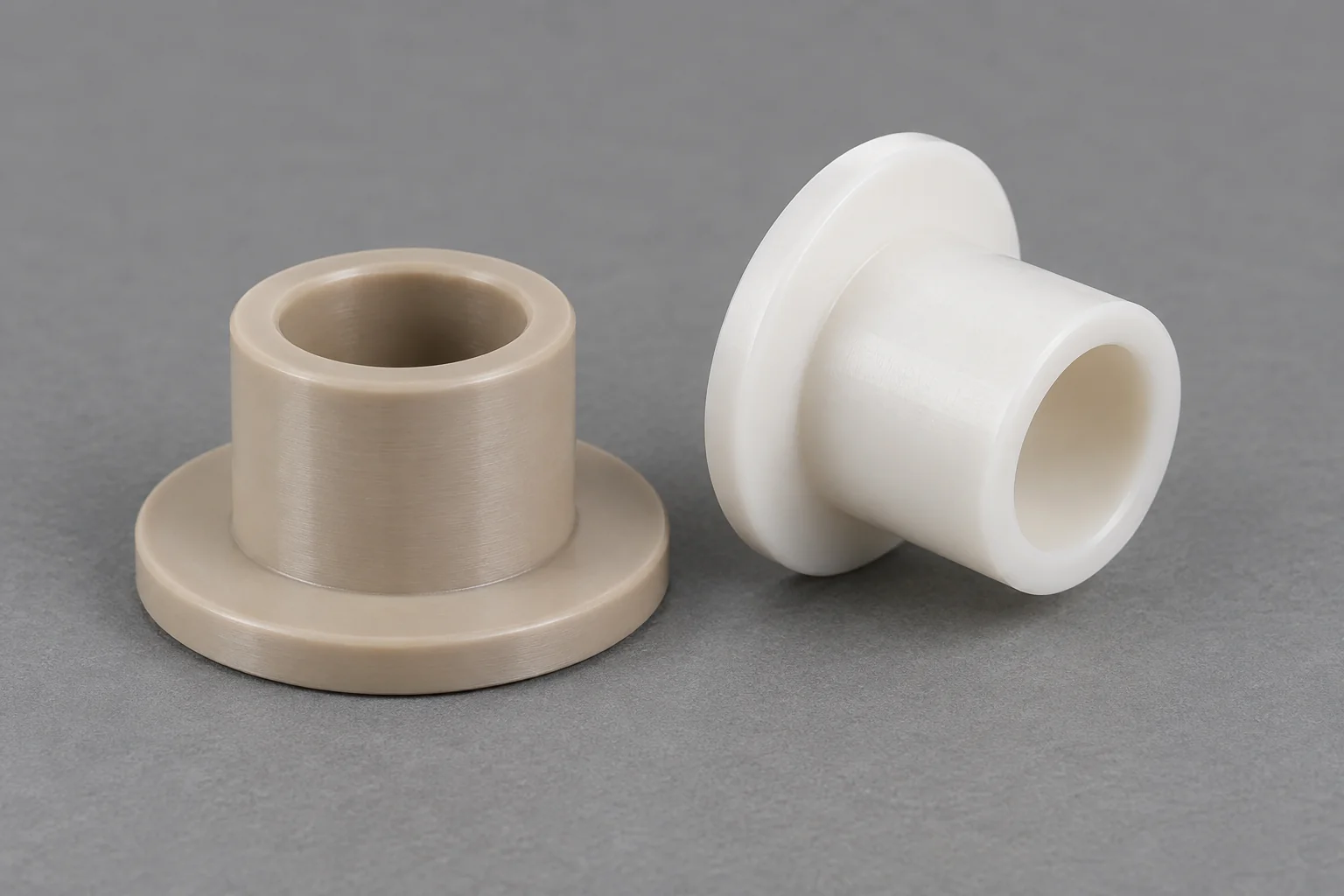
An integral flange provides axial location or a larger supported contact area.
Discuss this spacer →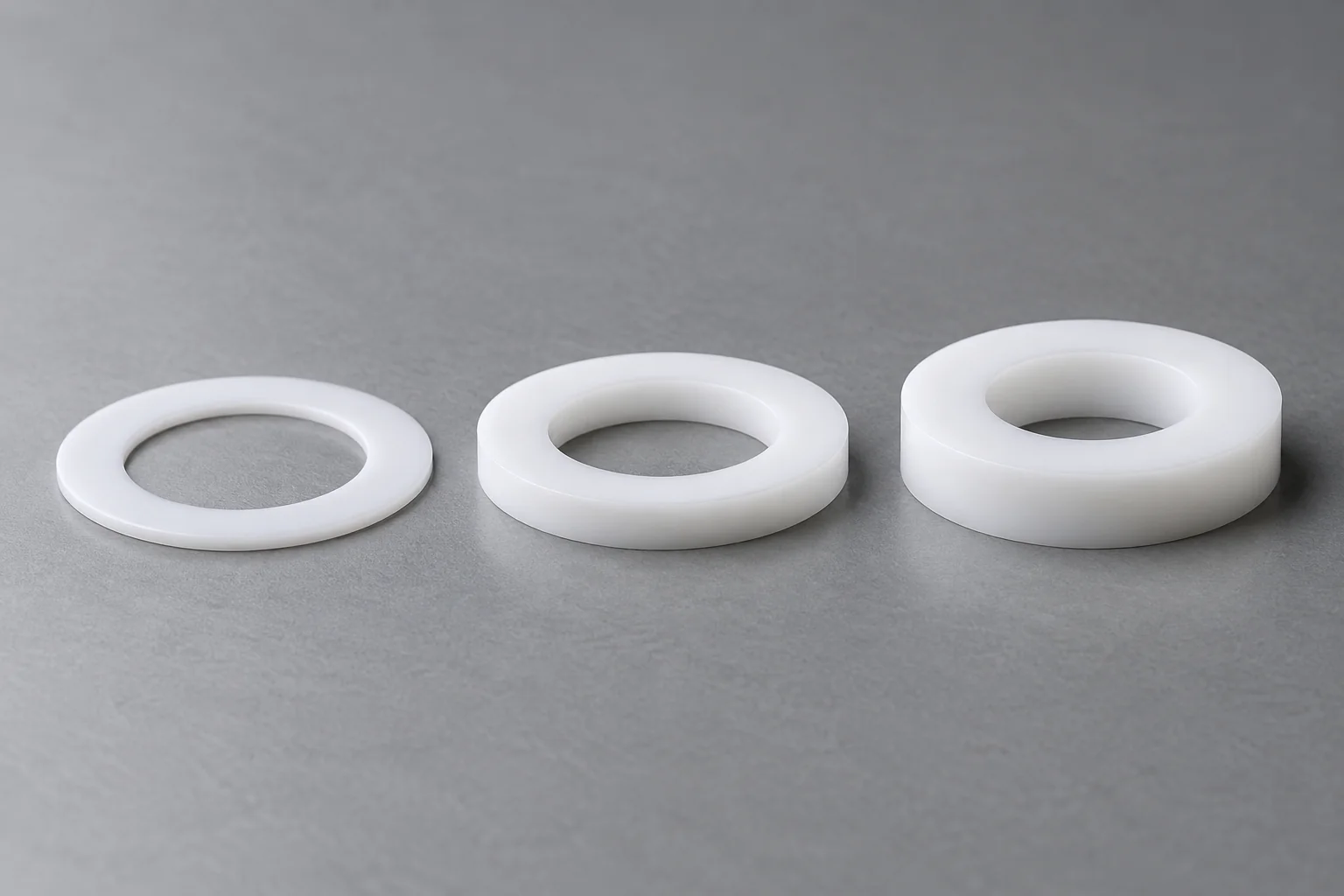
Thin precision spacing rings where controlled thickness and seating condition dominate.
Discuss this spacer →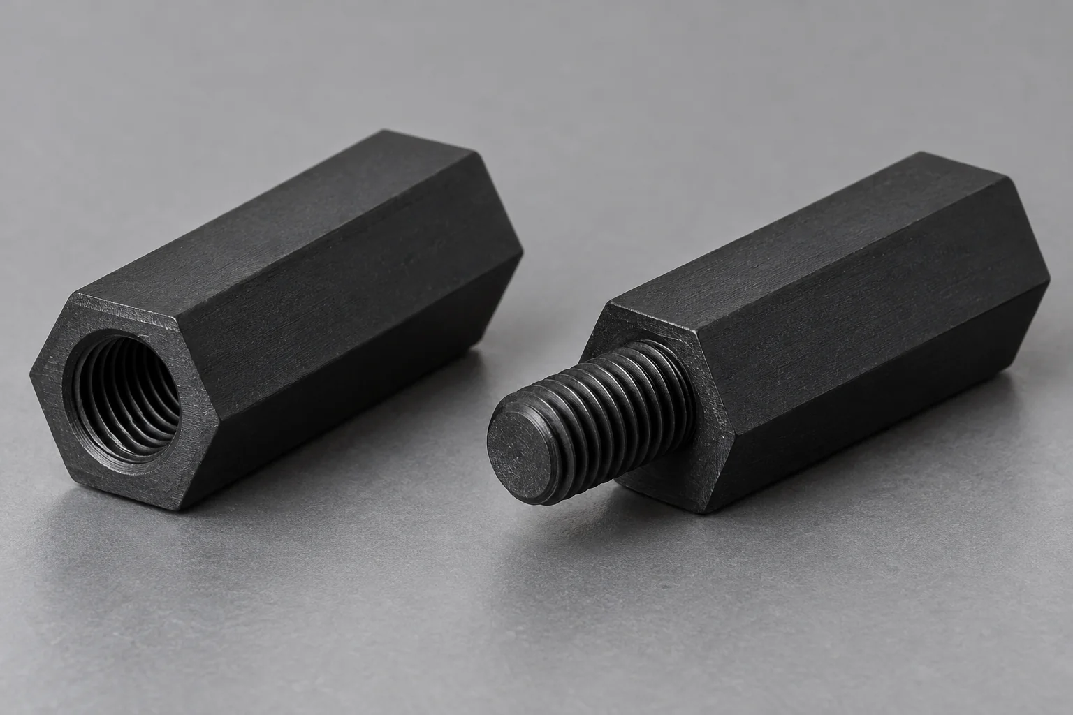
Internal or external threads combine spacing with a drawing-defined mounting function.
Discuss this spacer →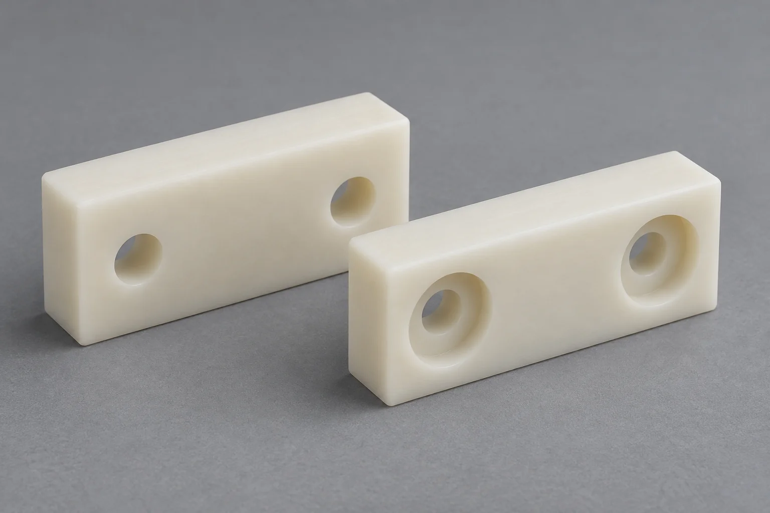
Rectangular or special-shaped spacing components for alignment and support where a cylinder is unsuitable.
Discuss this spacer →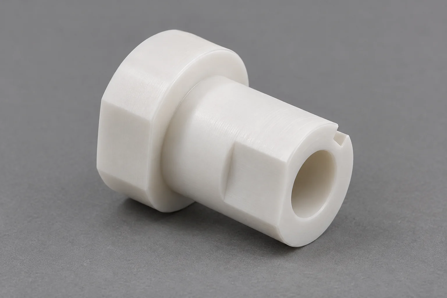
Flats, offset bores, keyways, grooves, eccentric forms and anti-rotation features made to your drawing.
Discuss this spacer →Plastic spacers maintain a controlled distance between two parts, position components, isolate surfaces, distribute fastener loads or provide electrical separation within an assembly.
Most spacers are not primarily designed to support continuous sliding motion. Their main role is geometric spacing, alignment, isolation or load transfer. A sleeve shape alone does not make a component a bearing: the function and its acceptance criteria determine the specification.
A spacer primarily controls distance, a bushing supports or guides motion, and a standoff typically combines spacing with a fastening function.
| Component | Main function | Typical geometry |
|---|---|---|
| Plastic Spacer | Maintains distance or isolates parts. | Sleeve, ring or block. |
| Plastic Bushing | Supports or guides a shaft or pivot. | Precision ID / OD sleeve, often flanged. |
| Plastic Standoff | Separates and often fastens two components. | Threaded or through-bore body. |
| Plastic Washer | Distributes local load or provides thin spacing. | Flat annular ring. |
Some geometries overlap. Specify the actual duty: static spacing, alignment, fastening, electrical separation or sliding motion. This page covers drawing-based OEM spacers rather than standard consumer hardware.
The benefit depends on the exact polymer, geometry and installed conditions.
Suitable insulating grades can separate conductive components in electronics and test fixtures. Voltage, environment and geometry require review.
A polymer spacer does not rust like ferrous metal. Chemical compatibility and stress cracking still need checking.
Lower component mass can be useful in moving equipment and weight-sensitive assemblies.
Unfilled engineering polymers can suit selected instrumentation duties; verify any fillers and assembled hardware.
Specific polymers suit particular media. Specify concentration, temperature, exposure time and cleaning agents.
CNC manufacture supports unusual dimensions, small quantities and drawing-specific features without dedicated molding tools.
POM is often considered for precision dimensions, Nylon for tough mechanical service, PTFE for chemical or electrical isolation, and PEEK or PEI for higher-temperature assemblies.
| Material | Main strength | Typical spacer use / review |
|---|---|---|
| POM / Delrin | Low moisture uptake and dimensional stability. | Precision mechanical spacers; confirm temperature and long-term compression. |
| Nylon | Toughness and useful mechanical performance. | General industrial spacers; moisture and conditioning affect dimensions. |
| PTFE | Chemical resistance and electrical insulation in suitable grades. | Chemical or electrical isolation; creep and low stiffness can limit clamp loading. |
| PEEK | Strength and thermal capability in suitable grades. | High-performance spacers; select grade against stress, time and temperature. |
| PVC | Useful electrical and chemical properties. | Electrical and process equipment; operating temperature and medium remain grade-specific. |
| Polycarbonate | Toughness and transparency. | Special equipment spacers; check chemical exposure and stress cracking. |
| PEI / Ultem | Heat capability and useful electrical performance. | Higher-temperature electrical spacers; confirm rating and moisture conditions. |
| PPS | Thermal, chemical and dimensional stability. | Technical precision spacers; filler, brittleness and insulation must be reviewed. |
Polymer names do not establish dielectric strength, flame classification or a load rating. Conductive, carbon-filled and ESD grades may not provide the electrical isolation of an unfilled insulating grade.
A functional drawing should identify the seating faces and the features that locate, clear or retain the mating components.
| Parameter | Customization and functional review |
|---|---|
| Outer diameter | Envelope or locating diameter. |
| Inner diameter | Fastener, pin or shaft clearance. |
| Length / thickness | Distance between the specified seating faces. |
| Flange diameter | Support area and axial seating. |
| Shoulder diameter | Location, isolation and mating-hole engagement. |
| Counterbore | Diameter and depth for the specified fastener head. |
| Countersink | Angle, diameter and remaining wall thickness. |
| Internal thread | Designation, engagement, depth and pull-out requirements. |
| External thread | Designation, engagement and root strength. |
| Chamfers | Assembly lead-in without removing the functional seat. |
| Flats | Tool access or anti-rotation. |
| Cross holes | Position and wall strength. |
| Offset holes | Datum-defined alignment and available edge distance. |
| Block geometry | Nonround spacing faces, pockets, slots or special profiles. |
The product images show common round, sleeve, stepped, flanged and block forms. Final geometry, minimum walls and achievable tolerances are reviewed against your drawing, grade and quantity.
Review the entire fastener stack. Bolt diameter, head area, preload, mating surfaces and plastic creep all affect assembly stability.
Spacing accuracy and clamp-load retention belong to the whole joint.
Allow adequate fastener clearance across the bore and bolt tolerances, alignment and temperature range. A clearance bore is not automatically a precision locating fit.
A small screw head can concentrate compression at the seating face. Include the head geometry and preload rather than only the nominal bolt size.
A larger effective contact area can reduce local stress. Check washer stiffness, flange thickness and the supported mating surface.
Shoulders and counterbores can locate mating components. Specify the controlling datums, engagement depth and intended clearance.
Engagement must account for polymer strength, thread root geometry, creep and repeated assembly. Inserts or alternate retention may be reviewed where appropriate.
Length or thickness is often the spacer’s most important functional dimension. Multiple component tolerances accumulate and can change the final assembly distance.
| Spacer A | 10.00 ±0.05 mm |
|---|---|
| Spacer B | 8.00 ±0.05 mm |
| Plate | 5.00 ±0.05 mm |
Illustrative arithmetic only; not a manufacturing tolerance promise.
The example shows a simplified worst-case linear stack. It assumes independent dimensional limits simply add; it is not a statistical tolerance analysis and does not include thermal expansion, seating deformation or compression.
Start with the required assembly height, identify the faces that control it and allocate each component’s tolerance. Avoid specifying unnecessary precision on nonfunctional surfaces while leaving the stack requirement undefined.
Sustained fastener preload can compress a spacer or cause time-dependent deformation. The result depends on polymer grade, temperature, geometry and clamping stress.
Increasing preload can increase deformation. Review effective annular contact area, local head pressure and the stiffness of the full joint.
Time-dependent deformation may relax the clamp load or change the spacing. A short-term compressive strength value does not establish long-term joint stability.
Elevated temperature often reduces stiffness and increases creep. Include continuous and peak temperatures, thermal cycling and dwell time.
Larger supported seating faces can reduce local stress. Actual load distribution also depends on face parallelism, washers and mating-part stiffness.
PTFE is especially sensitive to creep under sustained compression. Suitable PEEK or PAI grades can offer better load retention in demanding service, but still require time- and temperature-specific review. POM is useful for general dimensional performance; Nylon behavior also depends on moisture and conditioning.
Do not apply a generic metal-joint tightening torque to a polymer spacer assembly. Bolt preload, torque method, friction, contact area and allowable long-term deformation need a defined assembly specification.
Insulating spacers can separate components mechanically and electrically. Material properties and the complete assembly geometry must be reviewed together.
Control board height and fastener isolation while accounting for seating areas and component clearance.
Separate conductive hardware and locate test components to the drawing.
Maintain the sensor gap and isolate mounting interfaces where required.
Specify working voltage, dielectric requirements, creepage, clearance and the applicable design conditions.
Review insulation with temperature, moisture, contamination and adjacent conductive parts.
Mount internal components with the required spacing, flame classification and grade documentation.
Confirm dielectric requirements, continuous temperature, moisture exposure, material certification and any required flame classification for the exact grade and thickness. Creepage is a surface path and electrical clearance is an air path; an insulating polymer alone does not establish either distance.
No generic dielectric strength or UL rating is claimed for all plastic spacers. Conductive fillers, contamination, humidity and assembled fasteners can alter the isolation path.
Length / thickness, face parallelism and bore position often matter more than tightly tolerancing every external surface.
| Feature | Why it matters |
|---|---|
| Length / thickness | Controls the assembly distance between functional seating faces. |
| Bore diameter | Provides fastener clearance or a specified locating interface. |
| OD | Sets envelope or mating-hole location. |
| Face parallelism | Supports stable seating and uniform contact. |
| Face perpendicularity | Controls alignment to the specified bore or datum. |
| Shoulder height | Locates a component within the stack. |
| Counterbore depth | Determines fastener seating and remaining material. |
| Thread geometry | Affects engagement and fastening reliability. |
Define inspection temperature, conditioning, measurement force and whether the dimension is specified free-state or under an agreed load. Very thin rings and soft grades can deform during measurement. There is no blanket tolerance for every material, size and geometry.
Define how the spacer must perform in the assembly before choosing its material and individual dimensions.
Start with the final required separation and allocate tolerances across the whole assembly.
Review clamp stress and long-term deformation, especially for softer polymers.
Thin walls around holes or thread roots can split, distort or lose seating support.
Provide suitable supported area where compression is significant.
Review temperature, chemical exposure, moisture and electrical requirements together.
Differential expansion matters in plastic-to-metal assemblies and tight stack requirements.
Permanent clamp loads require time-dependent material and joint review.
Identify the seating datums that control the distance and any local contact requirements.
Machining follows the seating dimensions, fastener interface and special locating features.
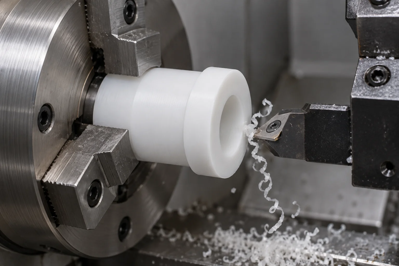
Produces OD, ID, length, shoulders, flanges and counterbores for round and sleeve spacers.
Creates spacer blocks, flats, offset holes and nonround profiles.
Produces clearance holes and drawing-defined internal or external threaded features with suitable engagement.
Removes unwanted burrs while protecting seating faces and the specified stack dimension.
Checks thickness, bore, face parallelism and shoulder dimensions to the agreed drawing and method.
Examples show common OEM uses; suitability and required documentation are agreed for the exact component.
PCB and enclosure spacing with grade-specific electrical review.
Precision fixture and insulating spacers with specified cleanliness and material requirements.
Structural spacing, bracket separation and sensor alignment.
Instrument and equipment assemblies with application-specific material requirements.
Brackets, guards and mechanical spacing components.
Insulating mounting parts matched to voltage, geometry and grade documentation.
Chemical-resistant spacing components reviewed against the process medium.
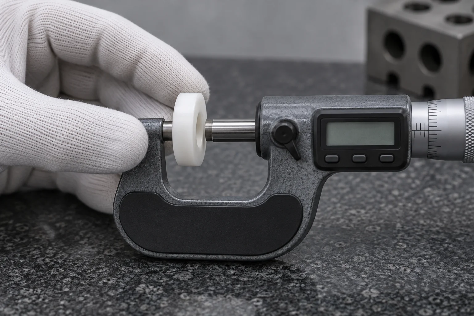
The inspection plan centers on seating faces and the dimension that controls the assembly stack.
Confirm polymer designation, filler and agreed material documentation.
Identify functional height, seating faces, datums and tolerance allocation.
Use appropriate contact force and support; avoid compressing thin or soft parts.
Check the fastener bore, locating diameter and specified size requirements.
Verify seating geometry and shoulder height against the required datums.
Check designated threads, depth, diameter and the fastener seating interface.
Inspect edges, bores and seating faces for the specified finish and unwanted burrs.
Protect critical surfaces, identify revisions and provide agreed inspection records.
Establish the functional assembly specification before repeating the production order.
Validate assembly height, fastener clearance, material and loaded seating behavior.
CNC manufacture supports specialized equipment without dedicated molding tools.
Use approved dimensions, material grade, revision and inspection criteria for recurring OEM orders.
A spacer may look simple, but its material, thickness, bore, compressive load, thermal expansion and creep can directly affect the alignment and clamp load of the complete assembly.
Geometry reviewed against your CAD model and functional drawing.
Round components and nonround blocks machined by the appropriate route.
Grade review considers dimensional, environmental and electrical requirements.
Functional seating faces and assembly distance guide the tolerance plan.
Shoulders, flanges, counterbores and threads follow the agreed drawing.
Initial assembly validation leads to a controlled recurring specification.
Measurement conditions and acceptance criteria agreed with the drawing.
Associated hardware and assembly requirements can be reviewed where specified.
Practical answers for specifying, selecting and sourcing custom polymer spacers.
Plastic spacers maintain distance, position components, isolate surfaces or transfer fastener loads. Common uses include equipment brackets, PCB mounting, sensor assemblies and insulating interfaces.
A spacer mainly controls distance, a bushing mainly supports or guides motion, and a standoff usually combines separation with fastening. Similar sleeve shapes can serve different functions.
No one material suits every spacer. POM is often considered for dimensional control, Nylon for toughness, PTFE for chemical or electrical isolation, and PEEK or PEI for higher-temperature service. Clamp stress, creep and environment decide the grade.
Yes, suitable insulating grades can provide electrical separation. Confirm the exact grade, voltage, thickness, creepage, clearance, moisture and required documentation; conductive or ESD grades are not interchangeable with insulating grades.
Yes, internal and external threads can be reviewed for machining. Provide the thread designation, engagement length, loading and assembly frequency; polymer strength and creep limit the fastening design.
Preload compresses the spacer and can concentrate stress beneath the screw head or washer. Geometry, supported area, temperature and material response influence deformation and clamp-load retention.
Yes, polymers can deform over time under sustained compression. The amount depends on grade, stress, temperature and duration, so short-term strength data alone does not establish long-term stack stability.
Functional thickness or length, face parallelism, bore position and shoulder height often control assembly performance. State the datums, inspection condition and any loaded-state requirement.
Thin spacing rings can be reviewed from the drawing. Grade, diameter, wall width, handling, flatness and measurement force affect feasibility; agree the minimum thickness and inspection method for the actual part.
Yes, we can review CAD models and drawings for custom spacer manufacture. Include the grade, OD, ID, thickness, fastener size, stack height, preload, temperature and any insulation requirement.
YOUR STACK. YOUR FASTENER. YOUR GRADE.
Upload your spacer drawing or CAD model and specify the material, quantity, outer diameter, inner diameter, length or thickness, fastener size, stack requirement and operating environment. TOPS Plastics can review the geometry, material and machining requirements before quotation.
Company, name, email and phone are required. Country, part number, quantity and drawing upload are optional. Include technical details in your drawing package or email to keep the form short.
info@tops-precision.comSTEP / STP / IGES / X_T / DWG / DXF / PDF or ZIP, maximum 10 MB. Larger packages can be shared by email. Agree confidential-file handling before sending sensitive drawings.