CNC Plastic Machining
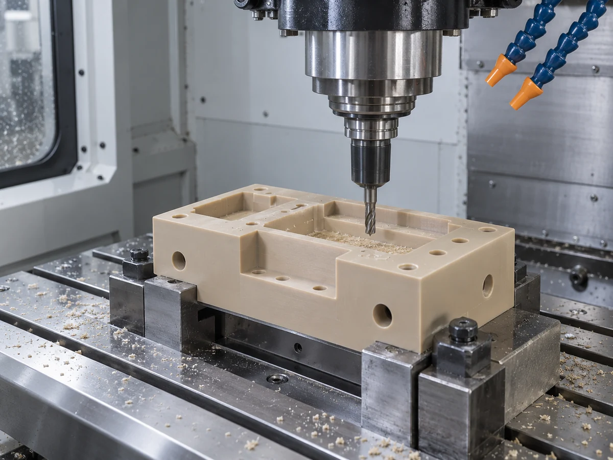
Machine pockets, holes, bores, threads and contours from suitable stock. Review datum relationships, workholding, cutting heat and the final released condition before assigning critical tolerances.
Learn more →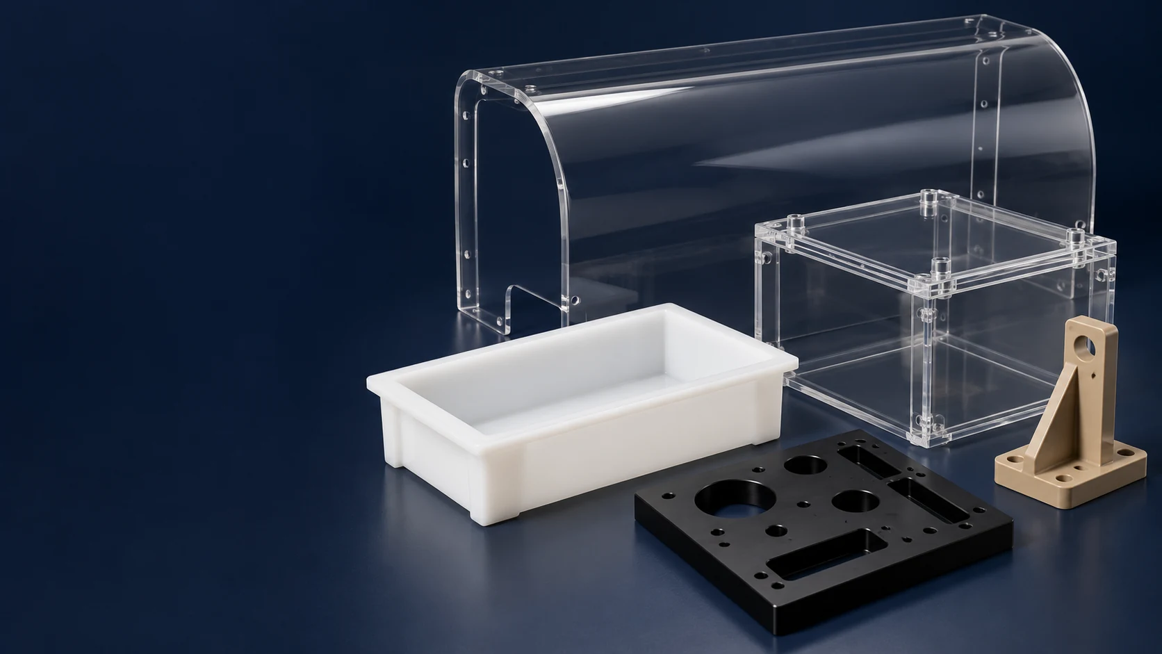
CUSTOM PARTS · MULTI-PROCESS FABRICATION
TOPS Plastics provides custom plastic fabrication for industrial components, prototypes and production parts. From simple cut and drilled panels to complex machined and assembled components, we plan a drawing-based route combining machining, cutting, drilling, bending, bonding, finishing and assembly as appropriate to the material and design.
Discuss PEEK, Delrin / POM, PTFE, Nylon, UHMW, Polycarbonate, Acrylic, PVC, PP, PVDF and other engineering plastics. Forming, joining and specialist finishing methods are reviewed for the exact grade, geometry and acceptance requirements before quotation.
A fabricated part may need several operations. We review the complete component or assembly rather than treating cutting, machining and joining as unrelated purchases.
| Capability | Project scope and review |
|---|---|
| CNC Machining | Milling, turning, drilling and tapping for drawing-defined features. |
| Cutting | CNC routing, sawing and profile cutting; acrylic laser cutting only where the grade, edge condition and confirmed route are suitable. |
| Forming | Bending and forming where material thickness, radius and appearance permit; thermoforming or vacuum forming requires separate feasibility and tooling confirmation. |
| Joining | Compatible bonding, mechanical fastening and welding routes reviewed for the material pair, joint design and service environment. |
| Finishing | Deburring, edge finishing and suitable polishing; engraving and cosmetic requirements reviewed against an agreed sample. |
| Assembly | Inserts, hardware and multi-part assemblies with defined fit, sequence and inspection. |
| Materials | Sheet, rod, tube and block in engineering and high-performance plastics, subject to grade and stock availability. |
| Production | Prototype, low-volume and repeat-production plans based on quantity, fixtures and revision control. |
| Files | STEP / STP, IGES / IGS, X_T, DWG, DXF, PDF or a ZIP package. |
| Inspection | Drawing-defined dimensions, appearance and assembly acceptance; functional testing scope agreed per project. |
The quotation confirms the actual manufacturing scope, any specialist operations and required documentation. A process listed here is not a universal capability for every polymer, size or geometry. Send your requirements if you need a particular joining, forming or finishing method.
Plastic fabrication converts plastic sheet, rod, tube or block into finished components or assemblies using machining, cutting, bending, forming, bonding, welding and finishing.
Unlike injection molding, fabrication commonly starts with existing stock material and does not necessarily require a dedicated mold. It can suit customized industrial equipment, large sheet components, prototypes and low-volume orders. Fixtures, bend tools or forming tools may still be needed; “no injection mold” does not mean that all preparation is free.
CNC machining is part of plastic fabrication. A guard may mainly need routing and bending, while a manifold may require precise milling, drilling and tapping. An enclosure can combine cut panels, machined interfaces, joints and hardware. The best route follows the material, geometry, demand and acceptance criteria.
Select the process for the functional result: a positioned hole, a sealing face, a transparent edge, a reliable joint or an assembled interface. Eight capability families cover different aspects of a fabrication project.
Machine pockets, holes, bores, threads and contours from suitable stock. Review datum relationships, workholding, cutting heat and the final released condition before assigning critical tolerances.
Learn more →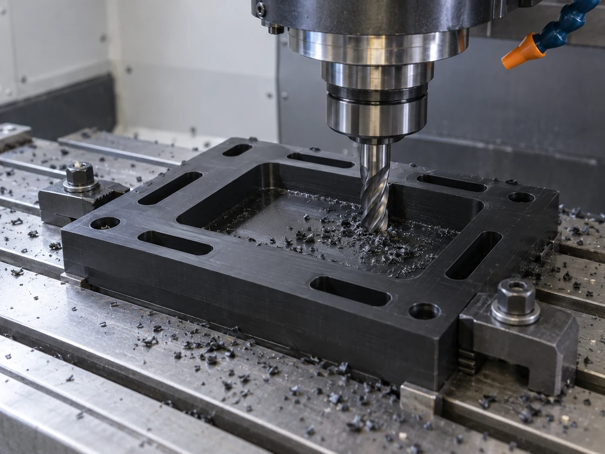
Mill prismatic housings, plates, manifold blocks and fixtures. Multi-face or contoured geometry may benefit from a different setup or five-axis route, subject to tool and fixture clearance.
Learn more →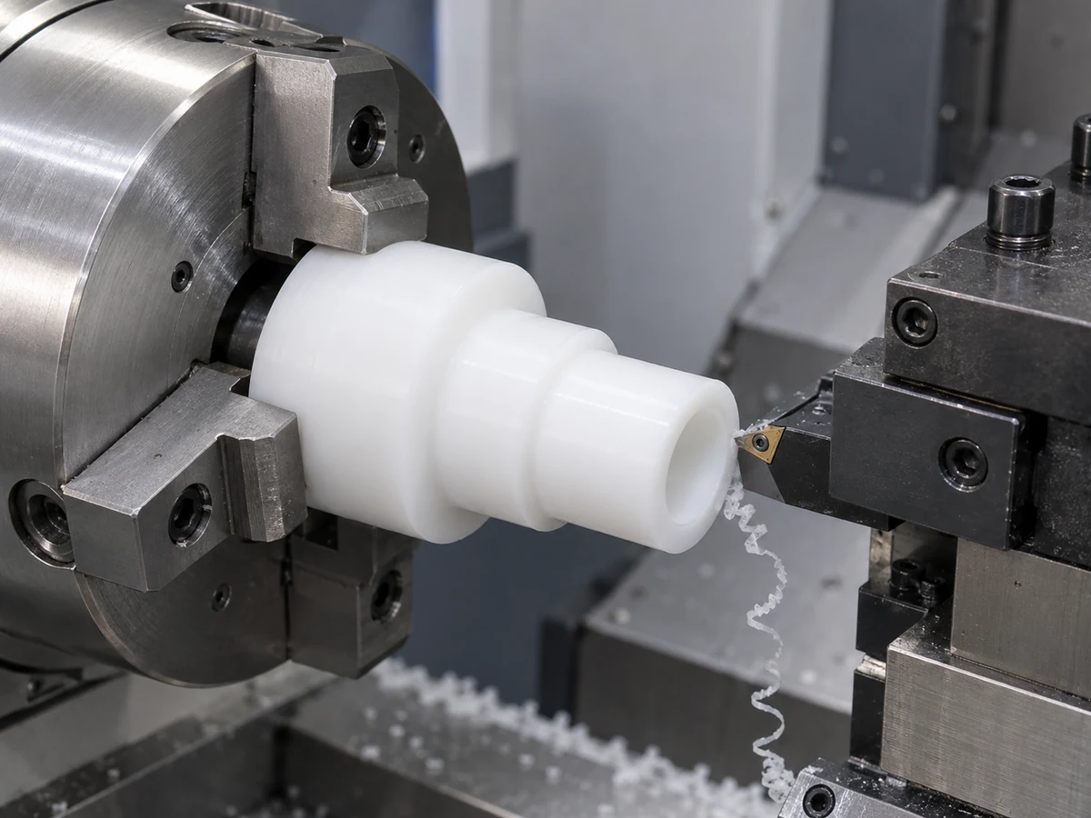
Turn bushings, sleeves, rollers, rings, spacers and threaded cylindrical components. Define the datum axis, bore and outside diameter, working fit, and any secondary off-axis features.
Learn more →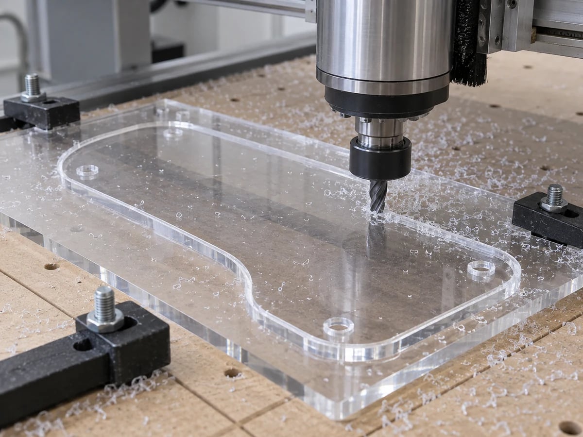
Use routing, sawing or profile cutting for sheet shapes and stock preparation. Acrylic may suit an appropriate laser route; polycarbonate is generally routed or machined. Evaluate heat, fumes, edge stress and material-specific handling before choosing a cutting method.
Learn more →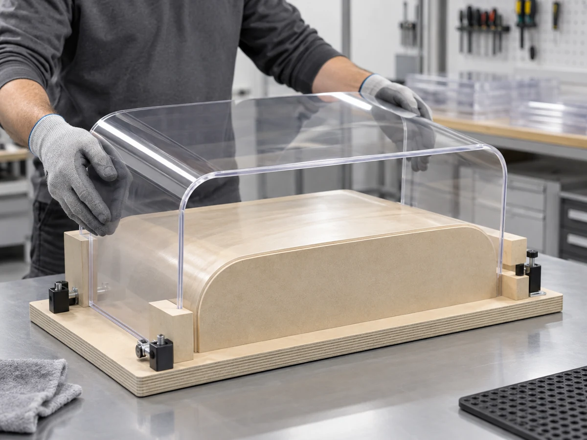
Produce suitable guards, covers, housings, trays, panels and enclosures by bending or forming. Review bend radius, thickness, springback and stress. Vacuum forming and thermoforming are project-specific routes requiring confirmed tooling and feasibility.
Learn more →
Join suitable panels or parts using a compatible solvent or adhesive system, or use mechanical fastening when serviceability is important. Joint preparation, bond gap, curing, chemical exposure and appearance requirements determine the plan.
Learn more →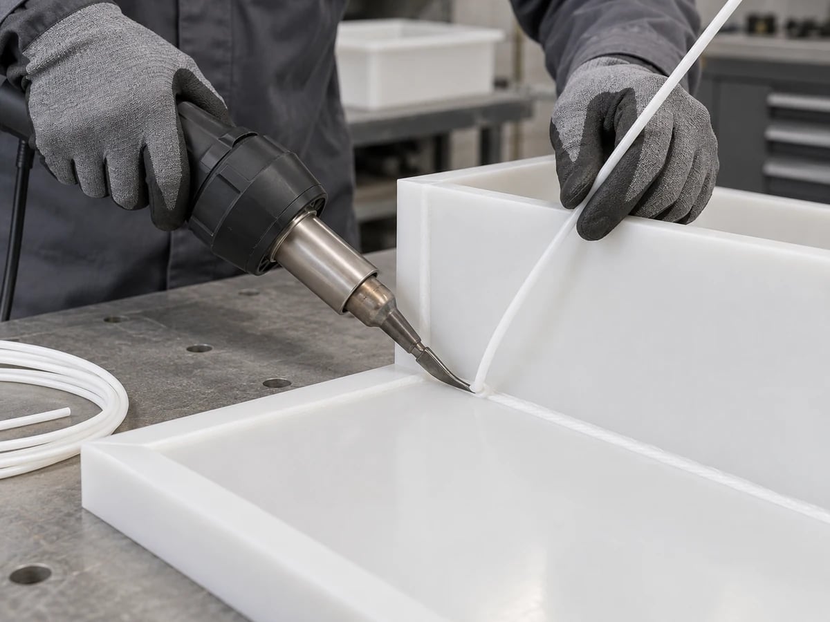
Review welding for compatible thermoplastic grades such as PP, PE, PVC and PVDF. Select the joining method and matching filler for the actual material; heat input, joint access and inspection affect suitability. Confirm the welding scope before ordering.
Learn more →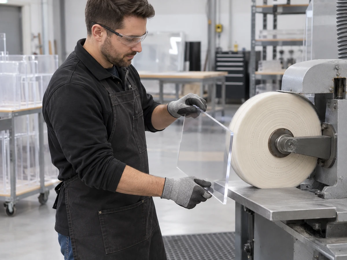
Deburr cut edges, finish or polish suitable surfaces and install agreed inserts or hardware. Engraving, appearance samples, protective film and assembly sequence should be specified. A polished edge does not by itself establish optical performance.
Learn more →Technical references: ACRYLITE acrylic fabrication manuals · SIMONA welding guidance
Discuss a multi-process fabrication project →Start with the required function and exact material, then compare feasible routes. Process selection must include the finished assembly—not just the easiest way to cut an individual part.
| Requirement | Candidate process | What to confirm |
|---|---|---|
| Tight tolerance features | CNC machining | Datums, measurement conditions, critical fits and released-part stability. |
| Complex 3D geometry | CNC milling / 5-axis machining | Tool access, internal corner radii, fixture clearance and reachable faces. |
| Cylindrical components | CNC turning | OD / ID relationships, part length, thin-wall support and runout. |
| Flat profiles | CNC routing / cutting | Sheet thickness, edge condition, support and hole locations. |
| Transparent polished components | Acrylic machining + suitable polishing | Grade, residual stress, appearance standard and required clarity. |
| Bent covers or guards | Bending / forming | Bend radius, temperature route, springback and mounting alignment. |
| Multi-part assemblies | Bonding / welding / fastening | Material compatibility, joint loads, access and future disassembly. |
| Prototype parts | CNC machining / fabrication | Test objective, representative material and critical acceptance features. |
| Large sheet components | Cutting + forming + assembly | Stock size, stiffness, handling, packaging and cumulative dimensions. |
For example, a viewing enclosure can use routed mounting holes, formed walls and a removable fastened cover. A machined chemical manifold follows a different route because port location, sealing surfaces and medium compatibility control the decision. These are illustrative design examples, not claims about completed customer projects.
Review five-axis options for complex geometry →Material determines whether a part can be machined, cut, formed, bonded or welded. Specify the supplier grade, fillers, stock form and documentation rather than relying only on a polymer family name.
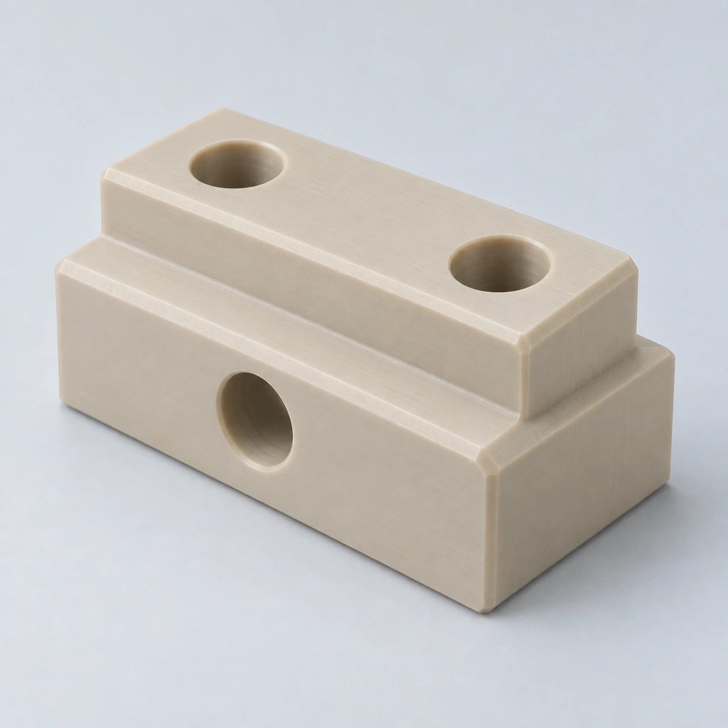
A high-performance candidate for demanding machined parts. Review exact grade, temperature, load and chemical environment; filled grades require separate machining and directional-property consideration.
Learn more →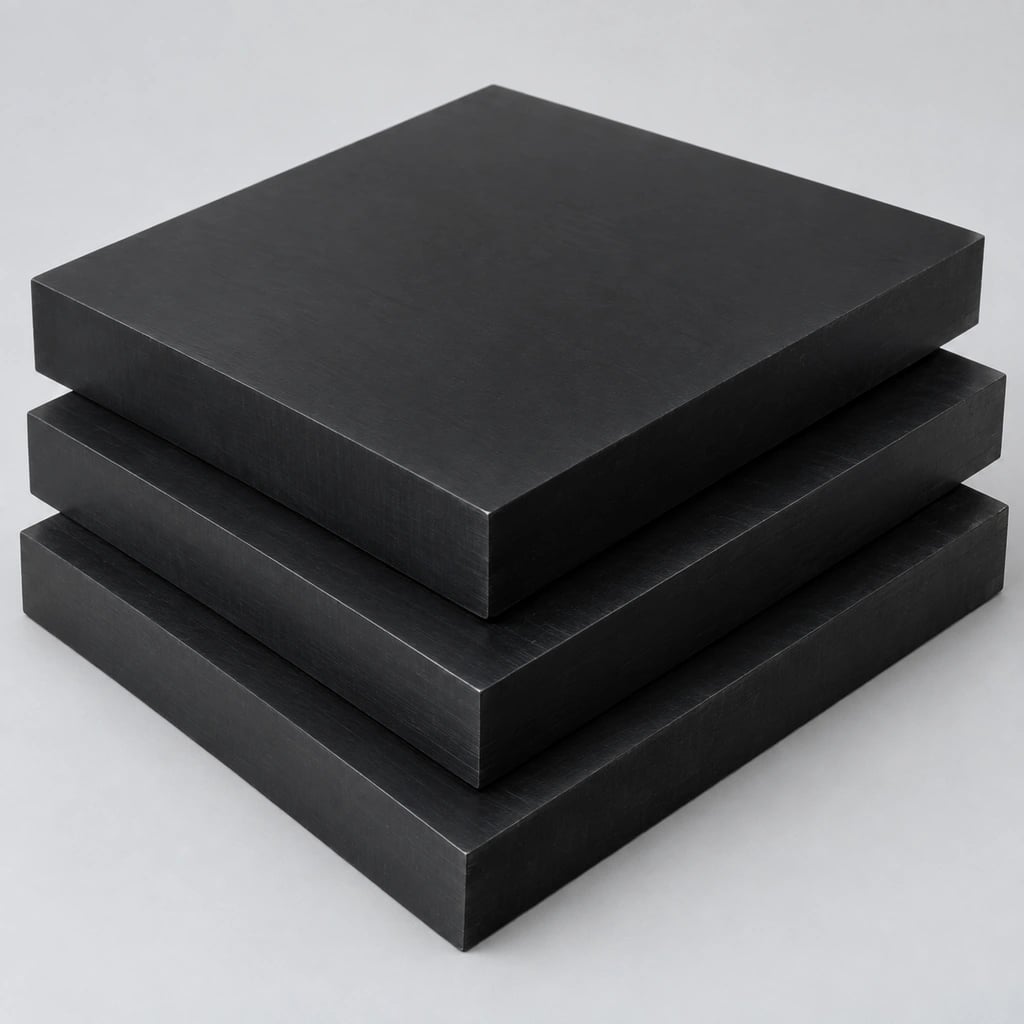
Often considered for dimensionally controlled mechanical parts and sliding interfaces. Distinguish homopolymer from copolymer; specify Delrin-branded material only when that brand is required.
Learn more →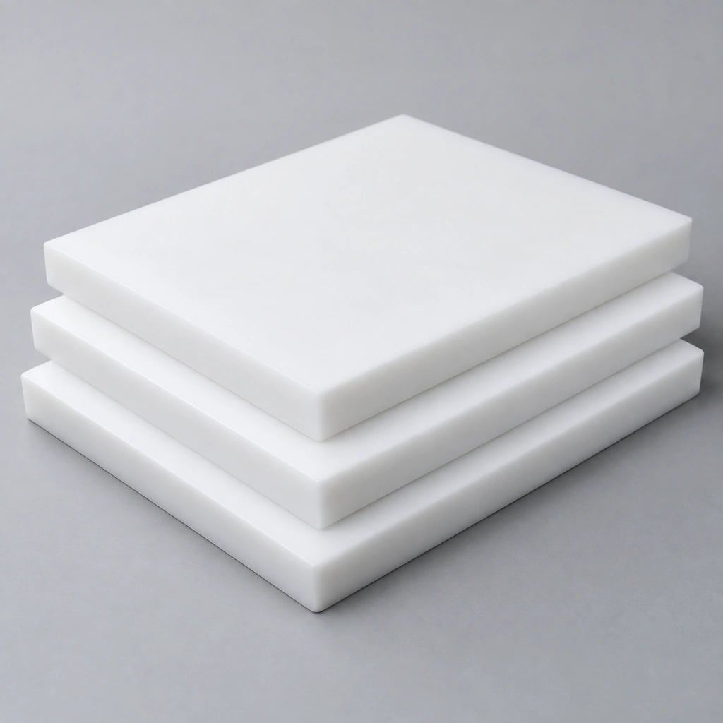
Used for chemical resistance and low friction. Creep, softness and measurement force can affect critical fits. Do not assume conventional solvent bonding will work without a qualified surface-treatment and joining system.
Learn more →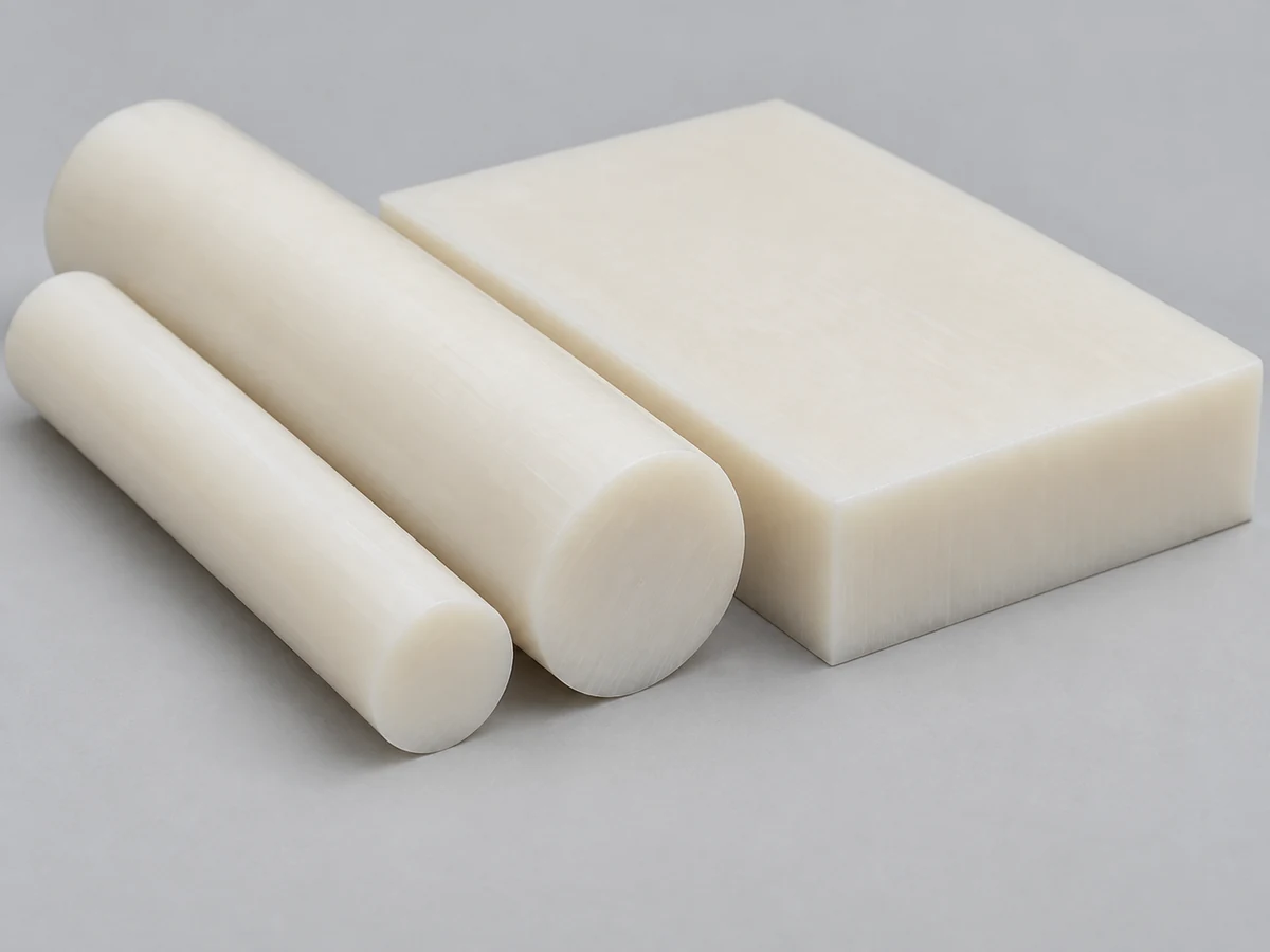
A practical wear-resistant option for mechanical components. Moisture conditioning can change dimensions; define the inspection condition and service environment when fit matters.
Learn more →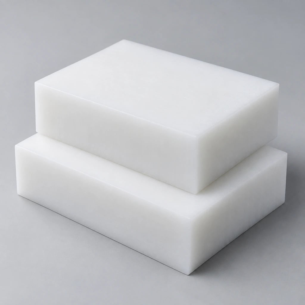
Often used for guides, wear strips and material-handling parts. Consider thermal expansion, flexibility, fastening support and the behavior of long sections.
Learn more →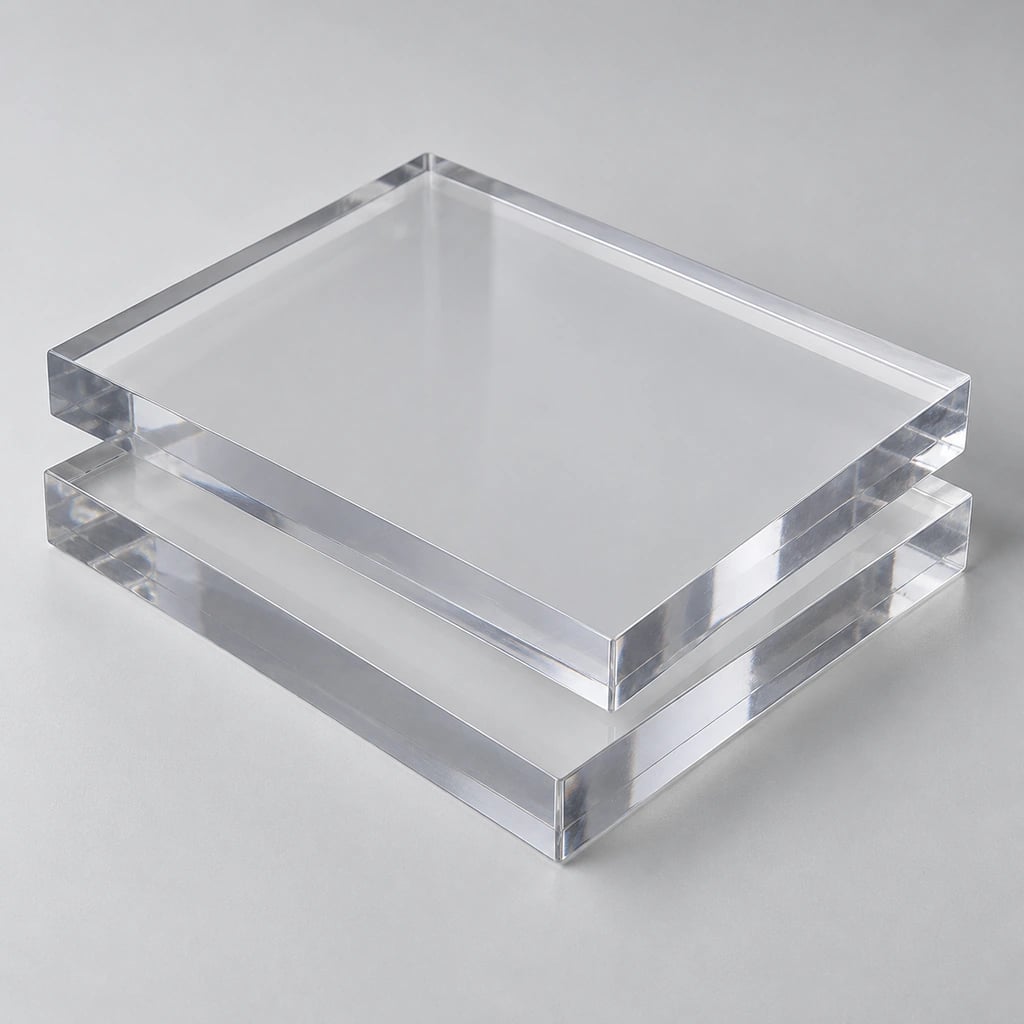
An impact-resistant transparent candidate for guards and covers. Specify thickness, grade and mounting details; routing and machining are generally preferable to a generic laser-cutting assumption.
Learn more →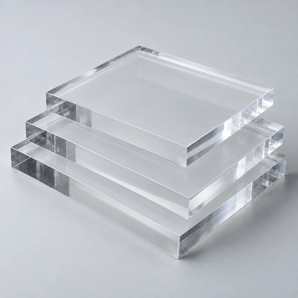
Suited to transparent fabricated components where appearance matters. Review machining stress, bonding, polishing and notch-sensitive features; clarity and structural strength are separate requirements.
Learn more →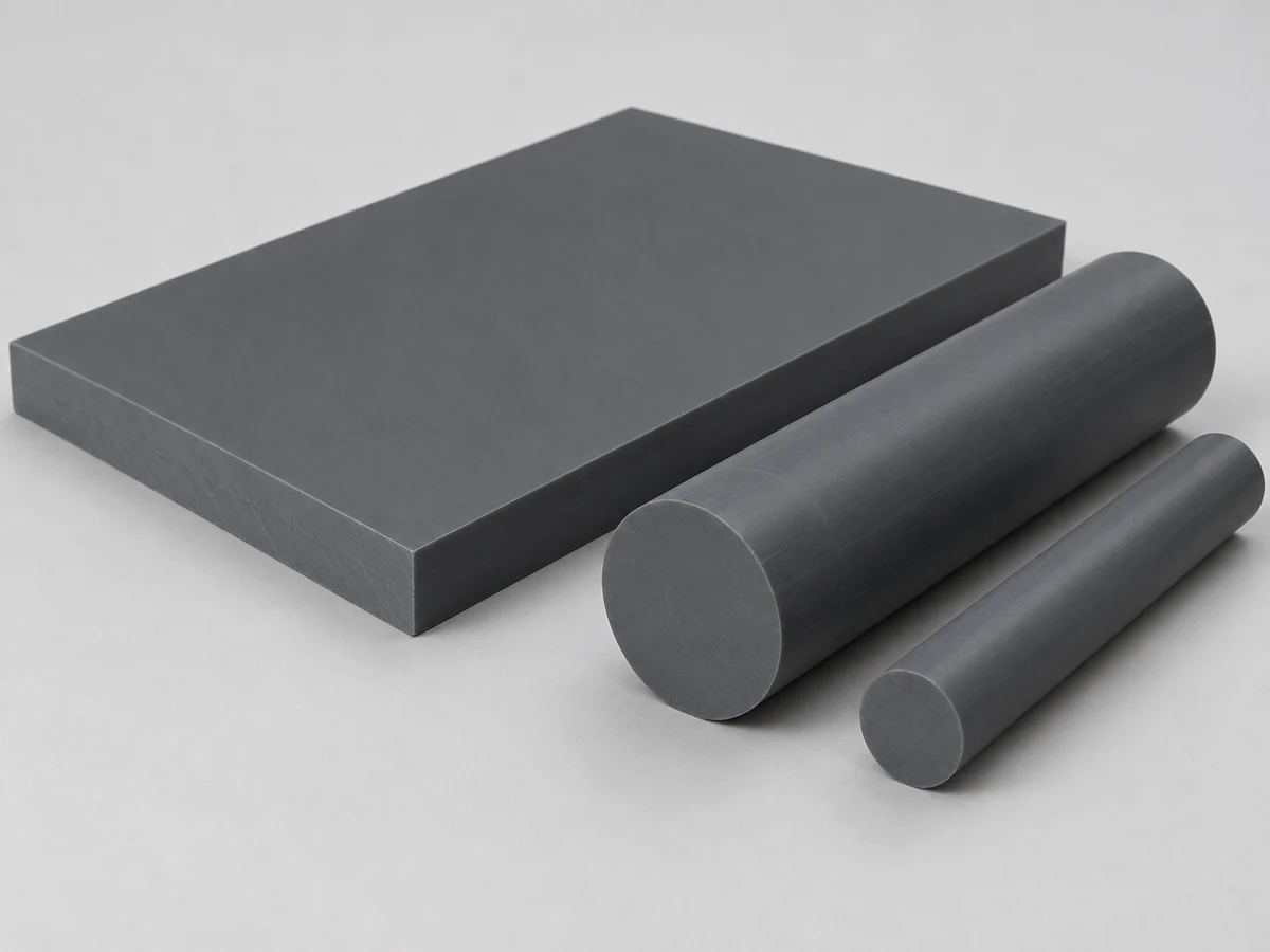
A candidate for chemical-service and industrial fabricated parts. Identify rigid or other specified grade and review joining compatibility, temperature and ventilation requirements. No blanket chemical-resistance guarantee applies.
Learn more →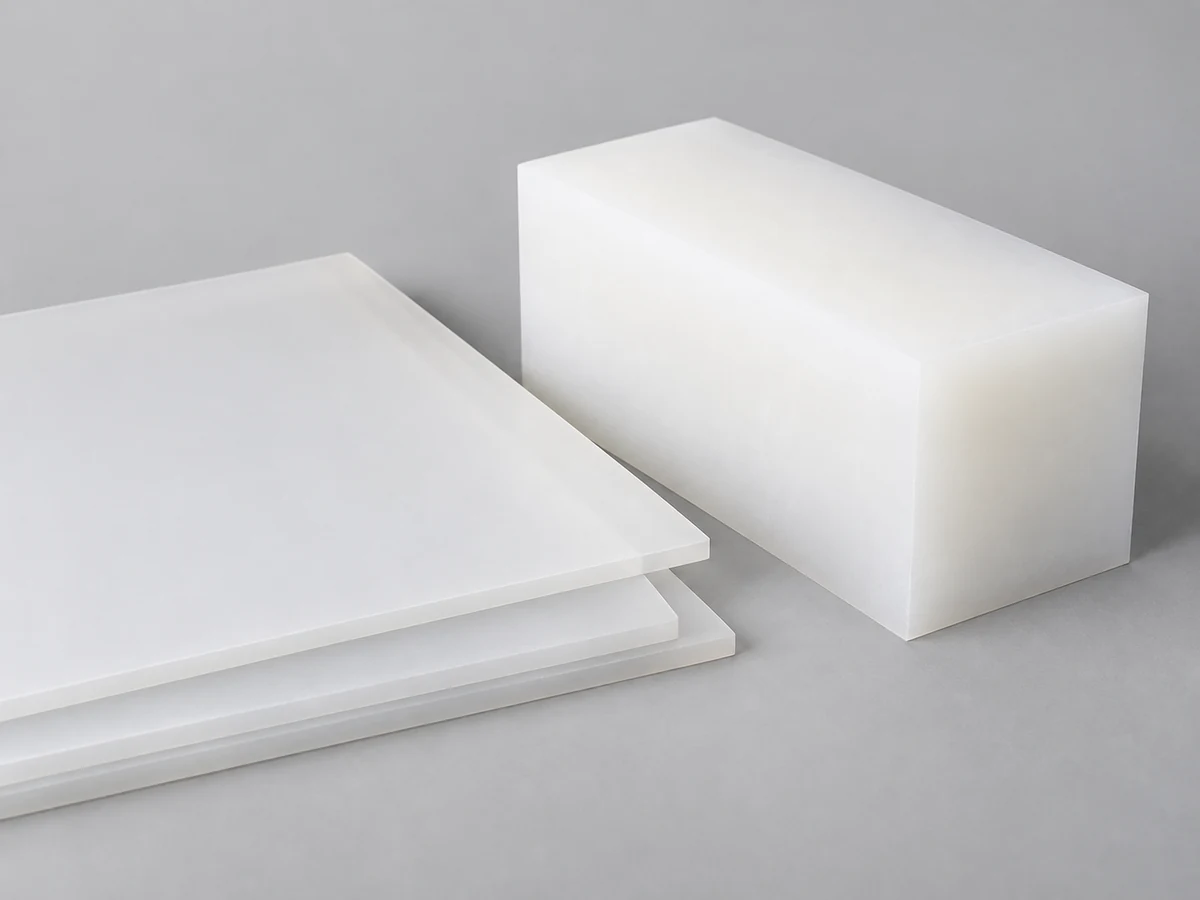
Often considered for chemical-resistant sheets, trays and compatible welded assemblies. Review stiffness, thermal movement, support and material-specific joining rather than treating it like acrylic.
Learn more →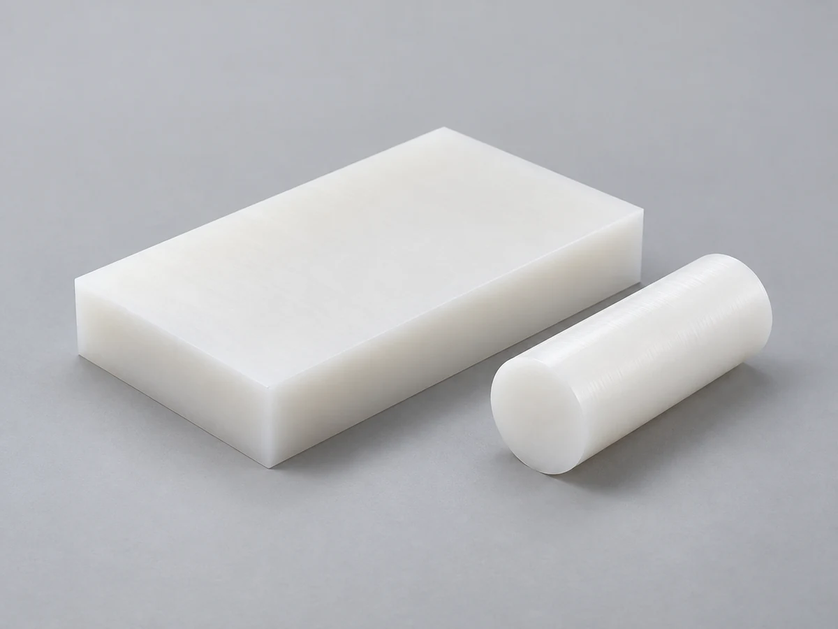
A candidate for selected chemical, fluid-handling and semiconductor-related components. Specify purity, grade and required records; the polymer name does not establish cleanroom or industry approval.
Learn more →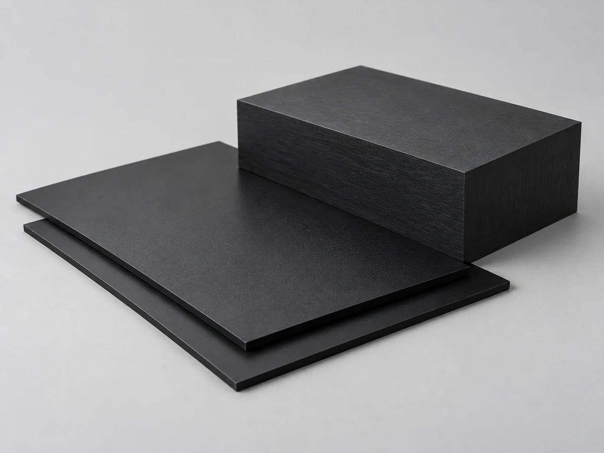
Useful for selected housings and equipment parts. Grade, impact behavior, solvent exposure and appearance requirements influence whether machining, forming or joining is appropriate.
Learn more →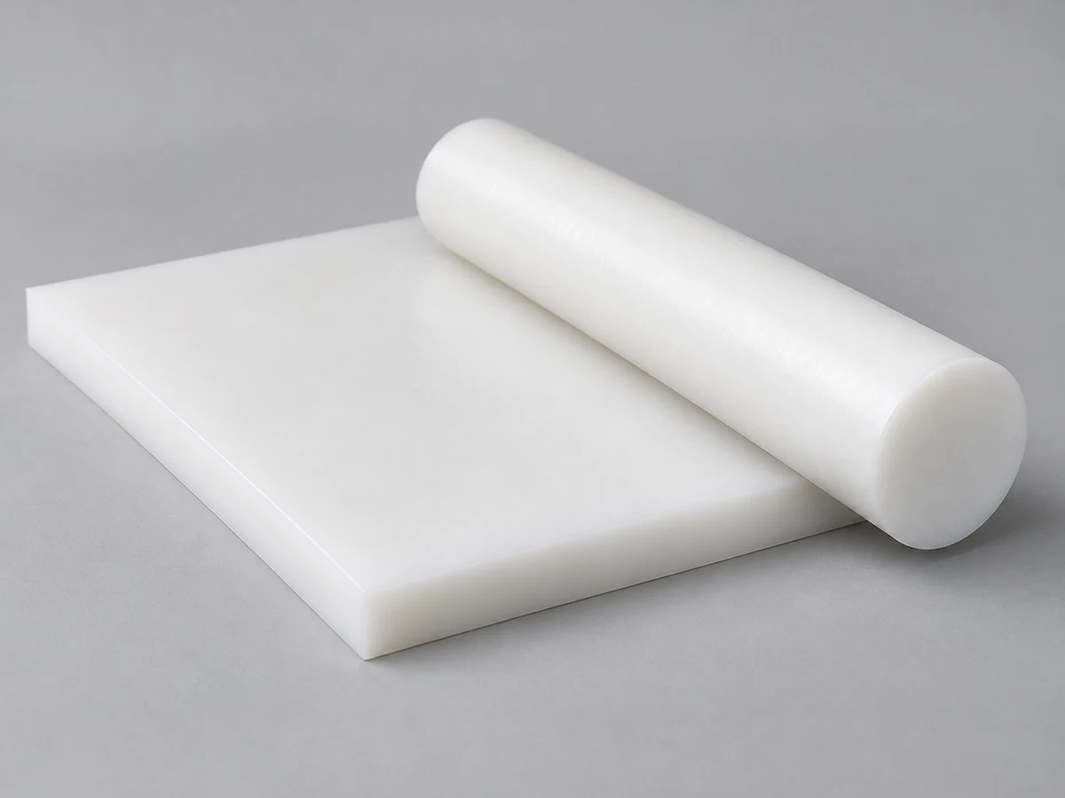
Consider for chemical-service or general fabricated parts where the grade is suitable. Support, creep and expansion affect assemblies; assess compatible welding or mechanical joining.
Learn more →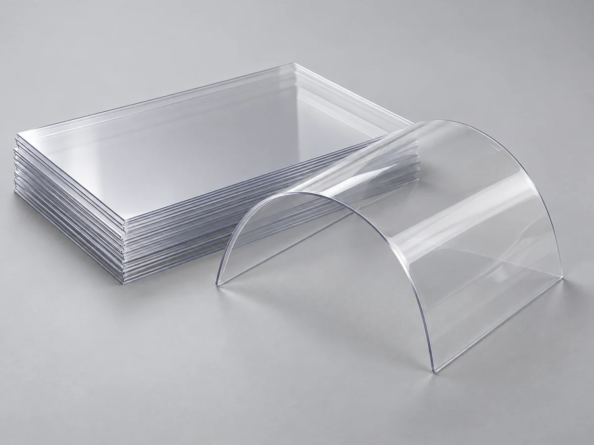
A transparent sheet option for selected covers and formed parts. Define grade, scratch sensitivity, cleaning agents and forming route before accepting it as a substitute for PC or PMMA.
Learn more →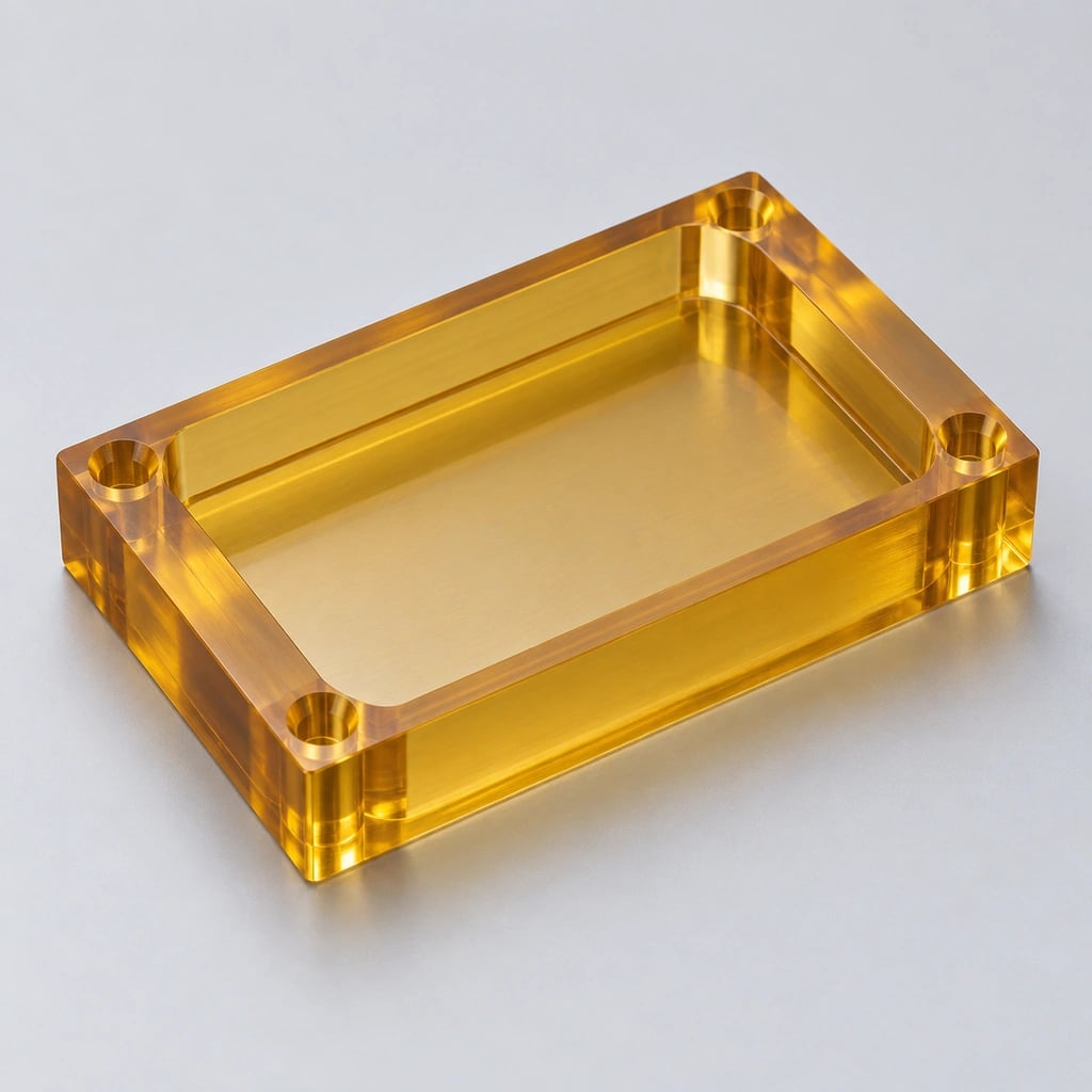
A high-performance material candidate for selected thermal and electrical applications. Confirm exact grade, stock availability, stress sensitivity and compliance documentation.
Learn more →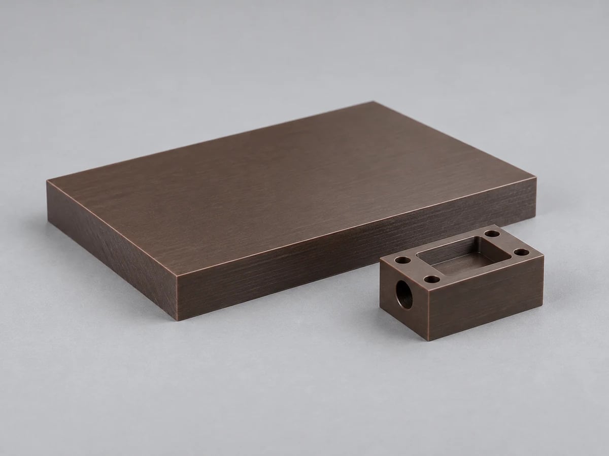
Often reviewed for elevated-temperature or chemical-service components. Reinforcement, stock orientation and the actual supplier grade can change machining and functional performance.
Learn more →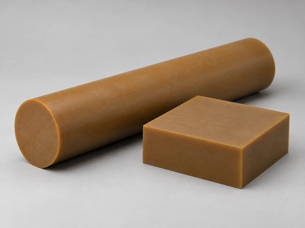
A high-performance polyamide-imide option requiring grade and stock review. Consider processing history, conditioning and inspection requirements; do not substitute grades without approval.
Learn more →Medical, food-contact, aerospace, flame-rating and semiconductor requirements must be established for the supplied grade and finished component. Stock availability, traceability and required declarations are confirmed during quotation.
We review custom components and assemblies against drawings, not fixed catalog dimensions. These distinct images illustrate product families and are not verified customer parts.
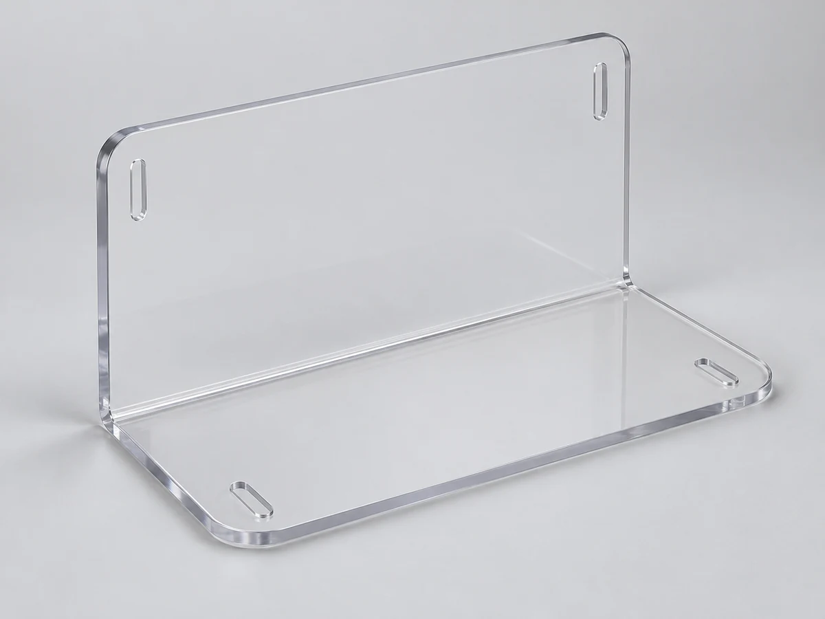
Cut and formed protective panels with accessible mounts. Safety performance, coverage and installation clearances must be specified and validated for the machine.
Learn more →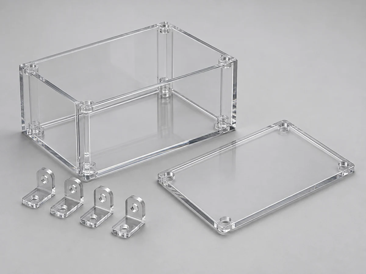
Bonded or fastened sheet assemblies with defined cover interfaces, access openings and joint appearance. Confirm environmental and service requirements.
Learn more →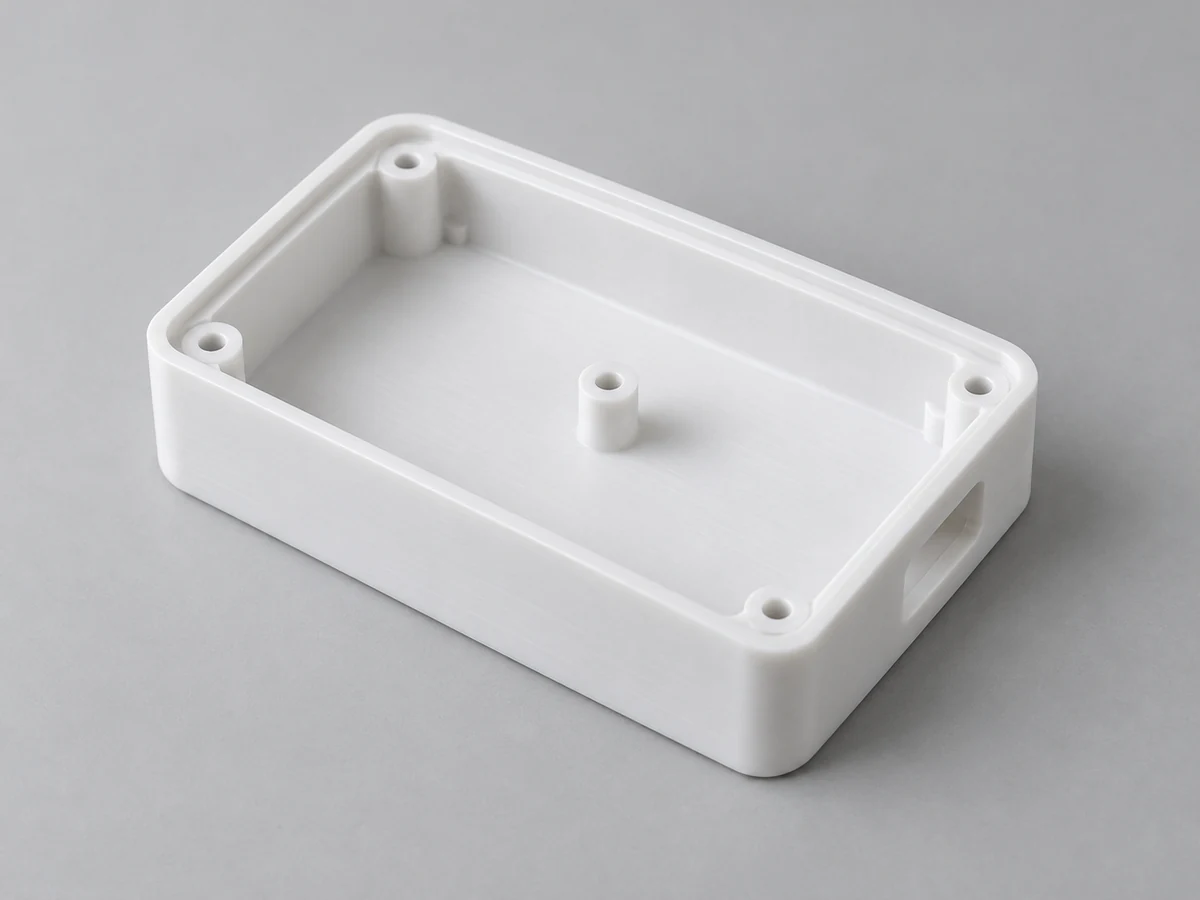
Machined equipment housings with bosses, cable openings and cover datums. Review wall support, threaded details and assembly loads.
Learn more →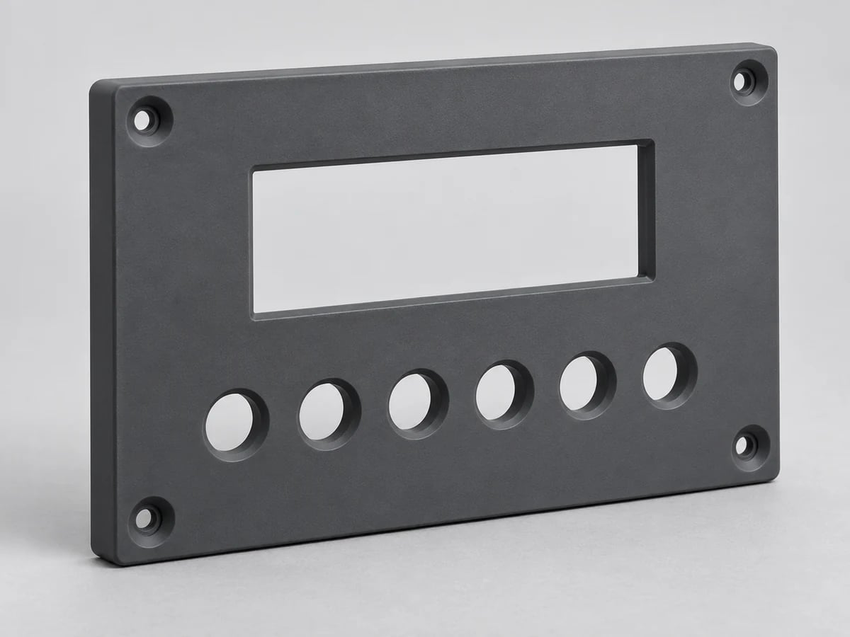
Profile-cut panels with display cutouts, holes and mounting patterns. Define flatness, edge finish and mounting reference features.
Learn more →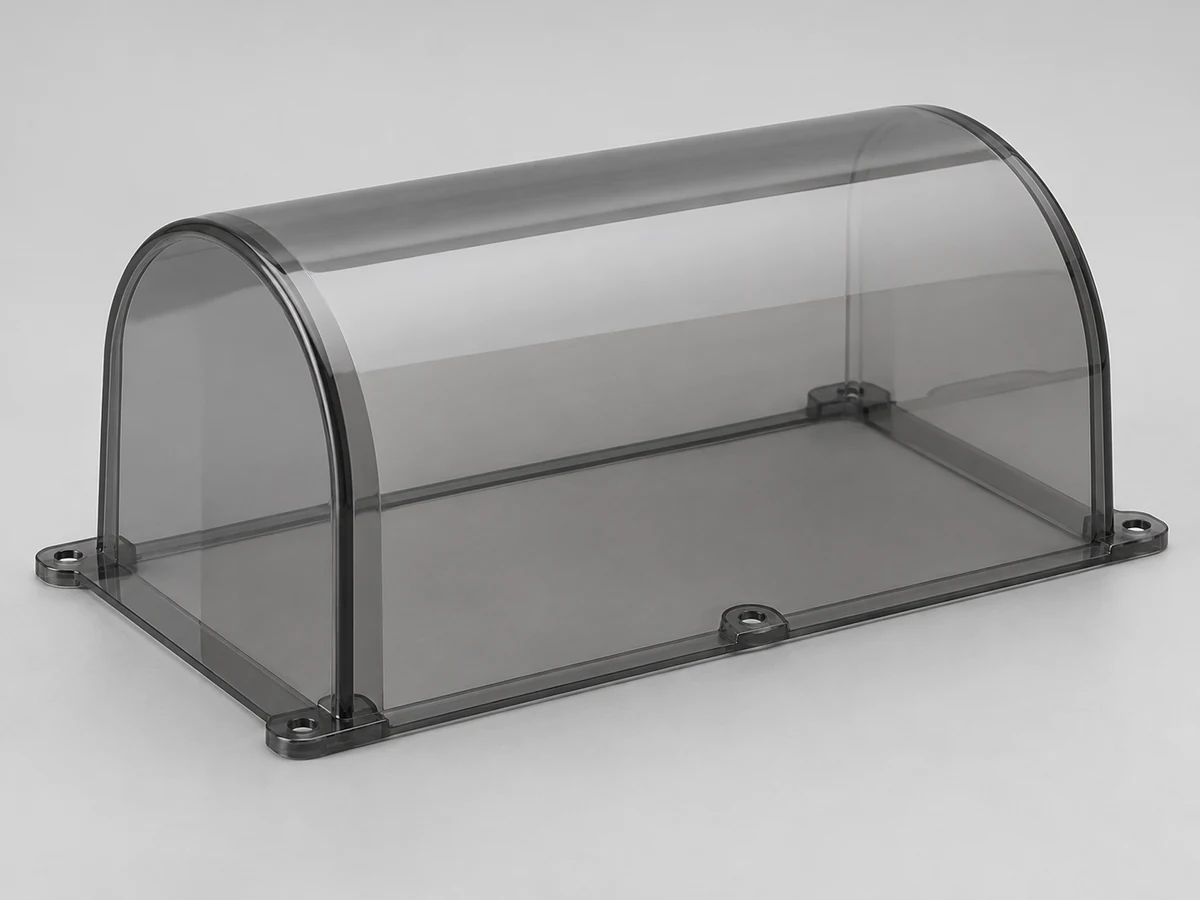
Bent or shaped covers with defined radii, screw positions and clearance. Consider springback, scratches and installation access.
Learn more →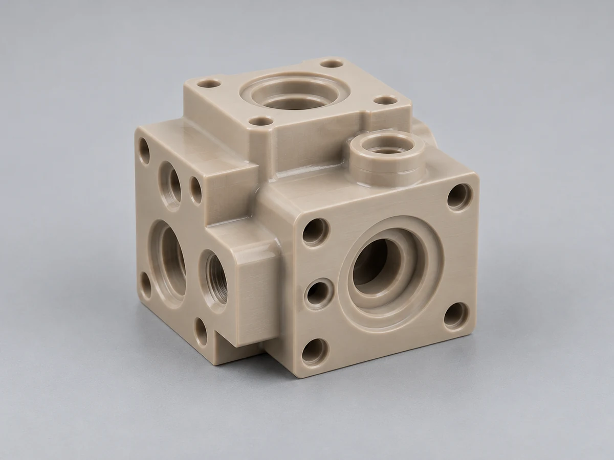
Machined flow components with intersecting ports and controlled sealing lands. Specify medium, pressure, temperature and required tests.
Learn more →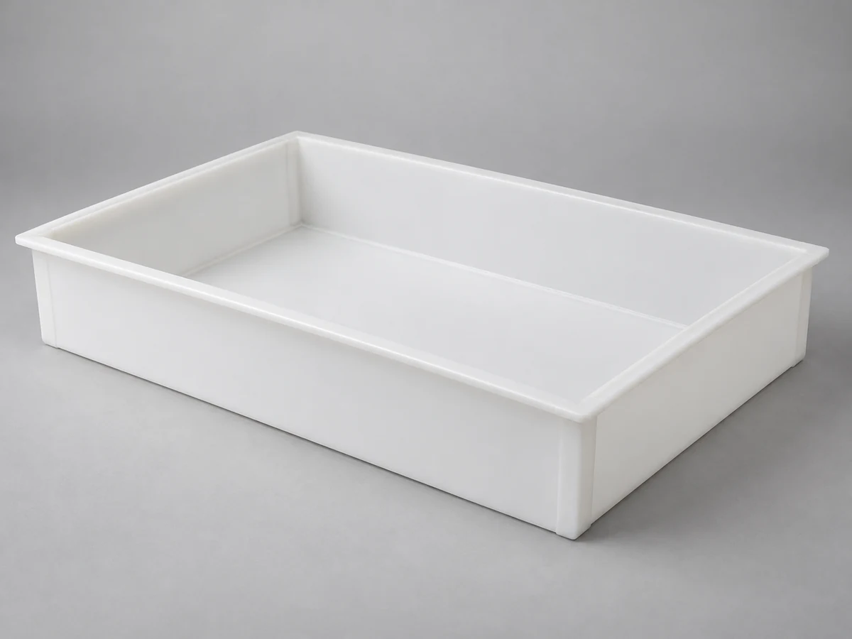
Fabricated containment or handling trays with compatible corner joints. Agree leakage, cleaning, load and appearance requirements where applicable.
Learn more →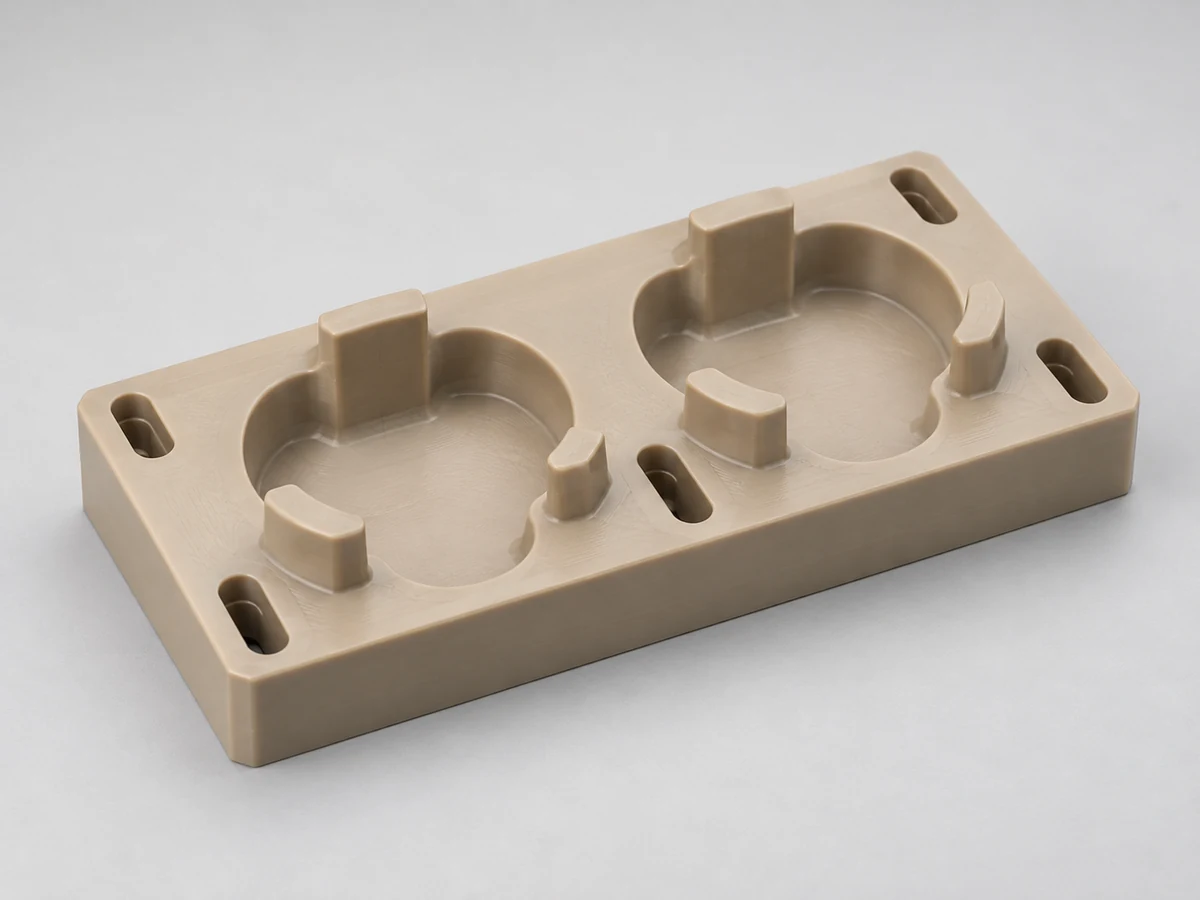
Drawing-based locating supports for assembly, inspection or production. Critical contact surfaces and datum relationships control acceptance.
Learn more →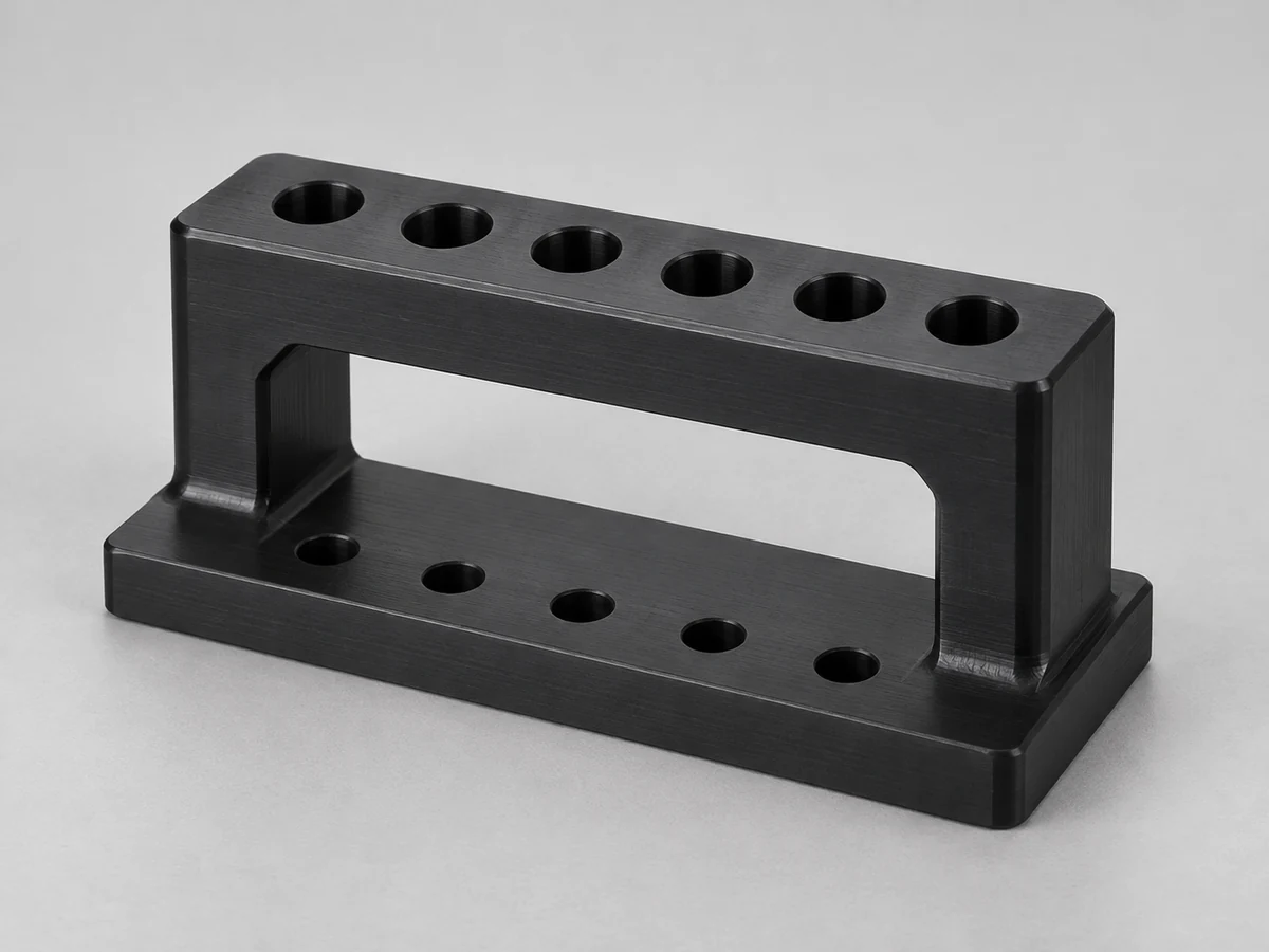
Hole patterns and guides for a defined operation. Include the mating equipment, support scheme and replaceable wear features.
Learn more →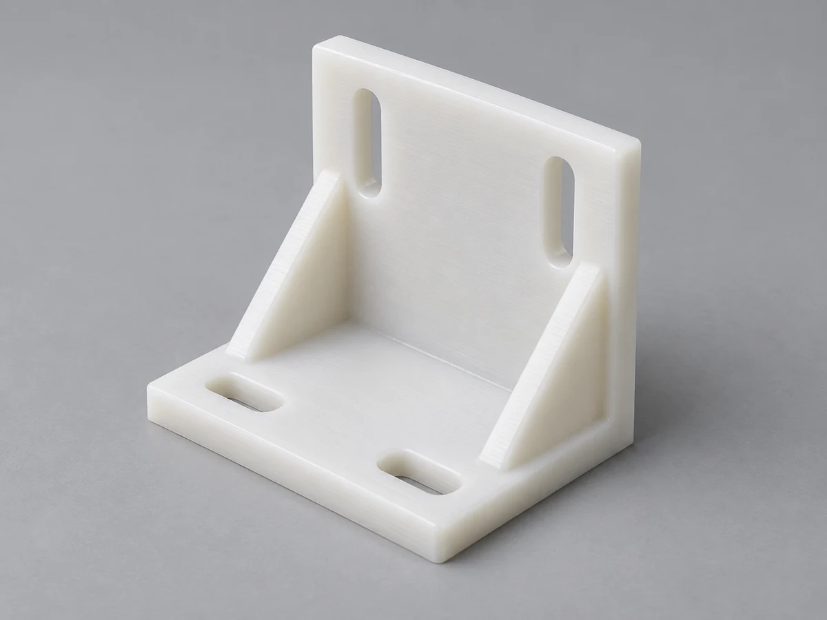
Machined or formed mounts with load-bearing faces and controlled hole positions. Specify fastener torque, orientation and deflection limits.
Learn more →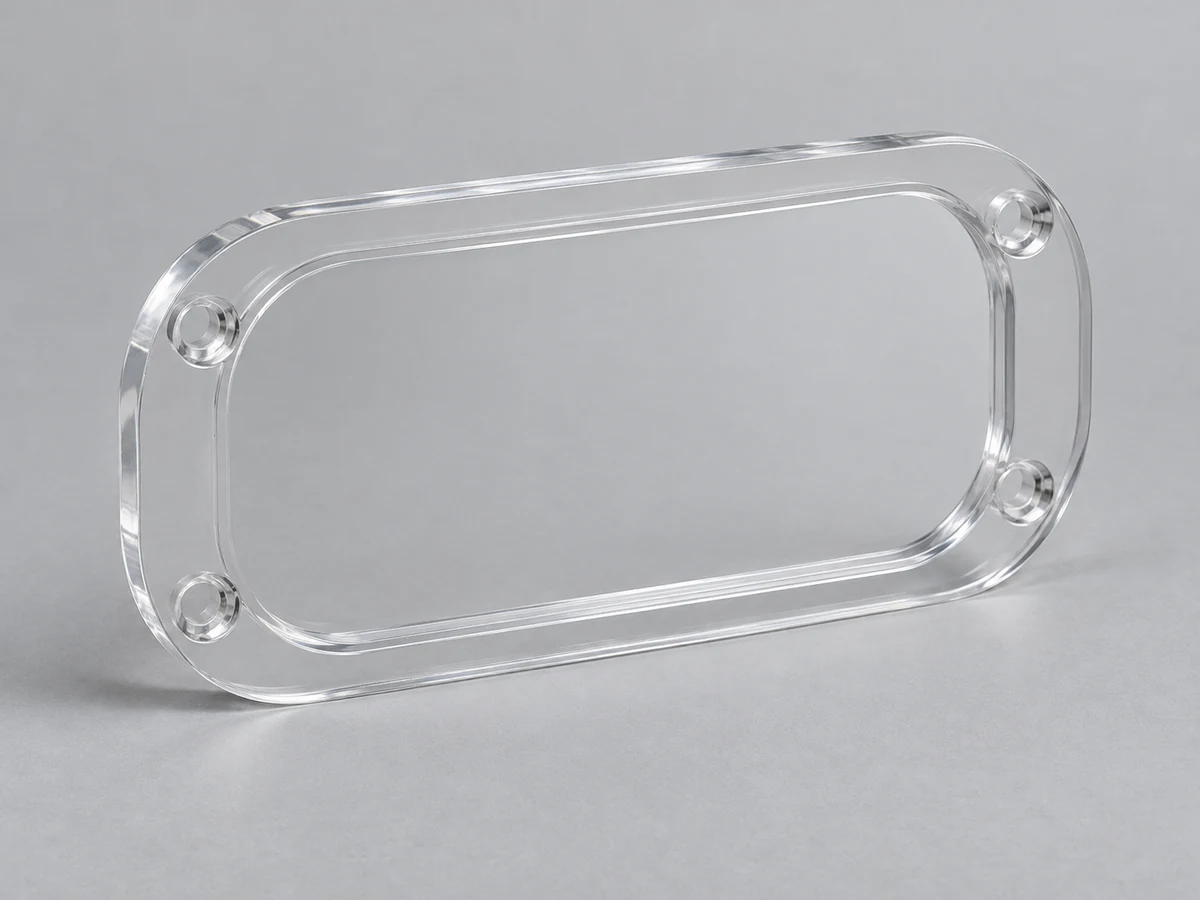
Transparent viewing parts with polished edges and located mounting holes. Define visibility, coating, cleaning and fit requirements.
Learn more →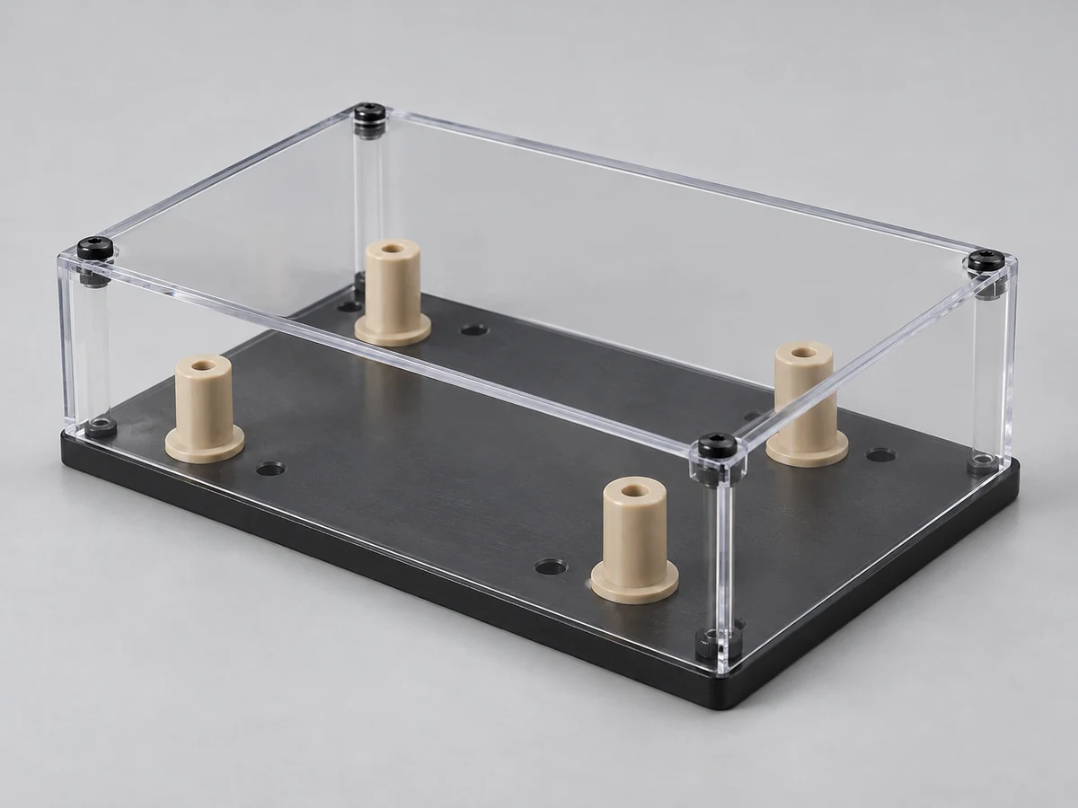
Multiple fabricated parts combined using a confirmed joint and hardware plan. Check cumulative dimensions, sequence and service access.
Learn more →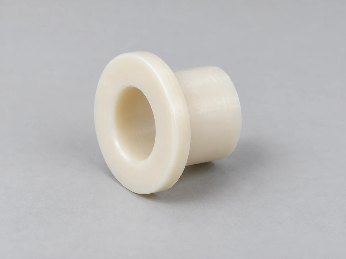
Turned bore and outside-diameter interfaces for shaft or housing fits. Review load, speed, lubrication and operating temperature.
Learn more →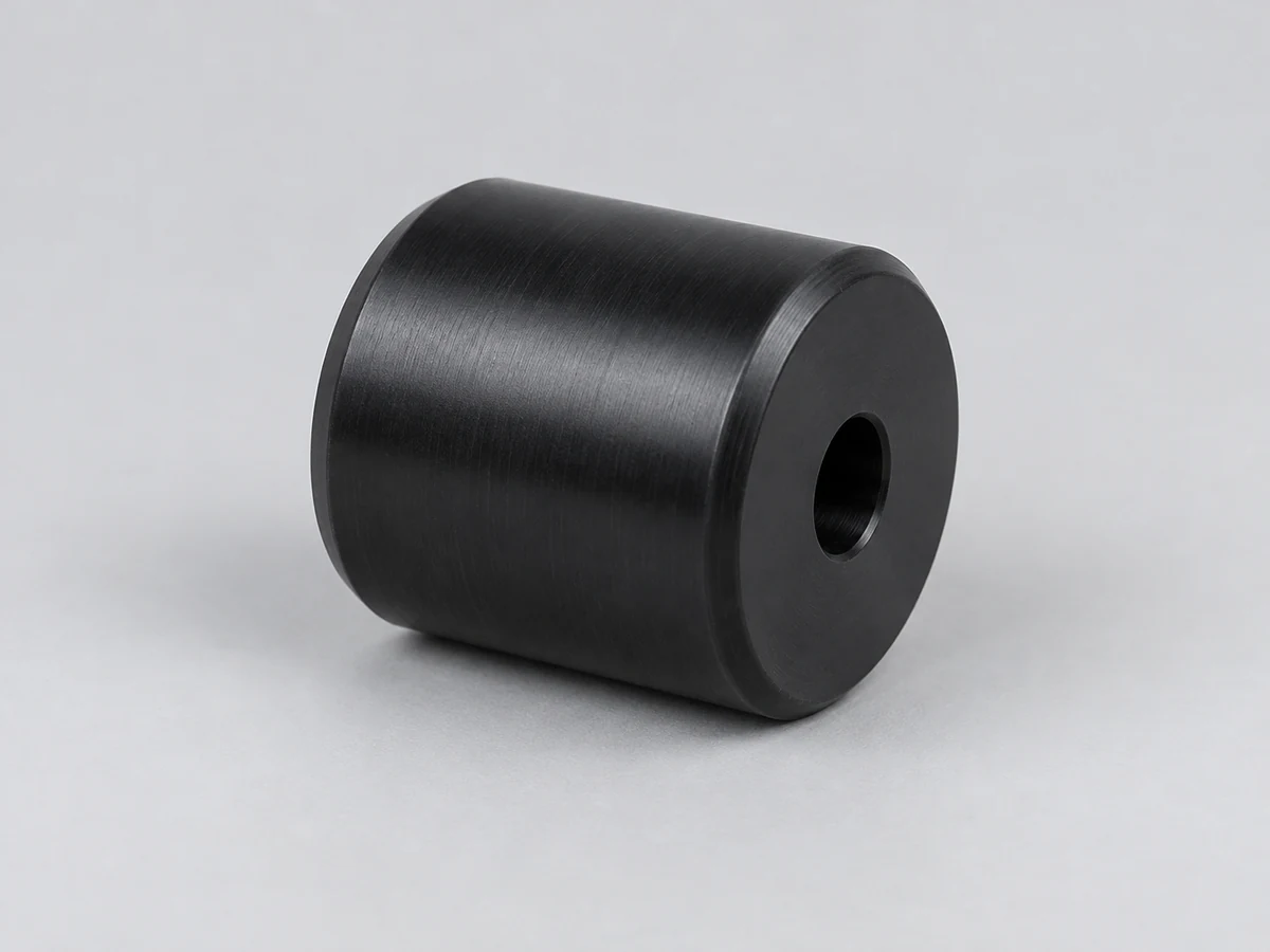
Turned working diameters and mounting journals for transport or handling. Specify runout, load and mating bearing interfaces.
Learn more →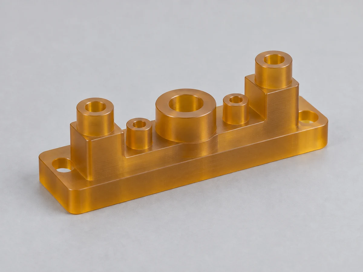
Machined electrical separation and mounting components. Exact grade, creepage or clearance design and required documentation govern suitability.
Learn more →Not all fabrication operations have the same tolerance capability. Define the functional dimensions and the method by which each will be measured; do not apply one blanket tolerance to the entire fabricated assembly.
| Process | Dimensional consideration | Drawing / acceptance requirement |
|---|---|---|
| CNC machining | Usually the strongest route for local precision features; grade, size and stress still matter. | Identify datum features, critical fits and inspection after release. |
| CNC routing | Suited to profiles and sheet features; support and edge condition influence results. | Specify profile, hole position, sheet thickness and reference edges. |
| Saw cutting | Useful for stock preparation and general dimensions. | Distinguish a rough blank from a finished acceptance dimension. |
| Bending | Bend angle, radius, springback and wall relationship vary with route and material. | Define final angle, radius, flange lengths and measurement condition. |
| Thermoforming | Can introduce wall thinning and greater dimensional variation than local machining. | Review tooling and feasibility; identify trim and machined secondary features. |
| Bonding | Joint fit, bond gap, cure and assembly fixtures affect final dimensions. | Specify joint geometry, cured inspection condition and acceptance evidence. |
| Welding | Heat input and restraint can affect seam shape and distortion. | Define joint and final dimensions; agree tests appropriate to service. |
| Assembly | Tolerance accumulation controls mating alignment and cover fit. | Give assembled datums, functional clearances and installation checks. |
Numerical tolerances are confirmed after reviewing material grade, feature size, geometry, process and inspection conditions. Temperature, moisture, creep and clamping force can influence the measurement. A drawing should state units and critical conditions when these affect acceptance.
For sealing or sliding interfaces, give the mating component and operating conditions. For guards or covers, mounting alignment and clearance may matter more than a very tight tolerance on every external edge. Finish samples and assembled fit checks often complement dimensional inspection.
Read the tolerance and RFQ checklist →Resolve material, joints, datum relationships and assembly access before freezing the design. A practical fabrication drawing communicates both geometry and what the part must do.
The actual polymer grade and stock form influence cutting, forming, joining and finishing. Specify chemical exposure, load, temperature and documentation; confirm substitutions before building samples.
Identify dimensions controlling fit, motion, sealing or alignment. Show datums and mating parts, and distinguish a reference dimension from a feature that determines acceptance.
Plastic dimensions can change substantially with temperature. Review differential movement against metal frames, slot or clearance needs, and the agreed temperature for critical measurements.
Concentrate precision on functional features. An unnecessary tight tolerance can add fixtures, secondary machining or inspection without improving performance.
Adhesive, solvent, welded and mechanically fastened joints need different geometry. Consider bond area, filler compatibility, restraint, cure or cooling, and the expected load path.
Choose a feasible radius for the material and thickness. Allow for springback and stress; avoid placing mounting holes so close to a bend that the forming process distorts them.
Leave space for cutters, clamps and joining equipment. Deep enclosed features or inaccessible inside corners may require an assembly or geometry change.
Define order of operations, hardware access and replaceable parts. Check the final assembly against functional datums rather than inspecting every part in isolation.
Many custom plastic parts require more than one process. A fabricated enclosure may combine cut sheet profiles, machined mounting features, formed walls, bonded joints, finished edges and installed hardware.
An illustrative enclosure route is shown below. Steps are selected where applicable; not every plastic can be bent, solvent bonded or welded. A fastened removable cover may be preferable to a permanently bonded seam when future servicing matters.
Review sequencing before production. Finishing can affect later joining, and heat introduced during forming or welding can affect previously machined dimensions. Where necessary, leave machining allowance or inspect critical interfaces after joining. Agree the order and acceptance points in the process plan.
The production route should match the stage of the project, quantity and design maturity. Define what a prototype must demonstrate before comparing it with repeat-production pricing.
Validate geometry, fit, appearance and the intended assembly sequence. Use representative material and joints where functional testing is planned. Document any substitutes or incomplete production features.
Build specialized equipment parts and small industrial batches using a confirmed route. Balance setup effort, stock sizes, finishing and inspection against the order quantity.
Maintain revision control, material identity, fixtures, process routing and acceptance criteria. A first article or reference sample can help align subsequent batches, with any changes reviewed before release.
Share initial quantity and expected repeat demand separately. Tooling, stock availability, joining fixtures and inspection effort can influence cost and lead time. Prototype approval does not automatically qualify every future material lot or production change.
Discuss prototype and repeat quantities →Application examples help define requirements; they do not establish certification or suitability without grade, drawing and acceptance review.
Positioning fixtures, trays, guards and fluid-related parts may need specified purity, cleaning and material traceability. Confirm chemical media, particle expectations and documentation.
Learn more →Equipment covers, housings and locating fixtures require drawing-defined function and cleaning compatibility. Biocompatibility, sterilization and device approval are separate, explicitly specified requirements.
Guards, wear guides, panels and mounted enclosures should be reviewed for vibration, load, access, fastening and maintenance conditions.
Lightweight brackets, jigs, covers and locating supports must suit repeat motion, wear, alignment and replacement needs. Provide installation and mating equipment details.
Panels, housings and insulating components depend on exact grade, thermal environment and electrical design. Required flame rating or declarations must be confirmed for the supplied material.
Manifolds, welded trays and compatible assemblies need medium, concentration, pressure and temperature information. Agree leakage or pressure-test scope where relevant.
Guides, covers and handling components need cleanability, wear review and any specified food-contact documentation. Polymer family alone does not establish regulatory acceptance.
Drawing-based brackets, housings and insulators require explicit material and quality records. Manufacturing a polymer component does not itself establish aerospace approval.
Fixtures, prototype covers and equipment components can require heat, vibration, chemical and assembly checks. Specify whether the part is for production tooling or a vehicle application.
Fabrication quality includes dimensions, material identity, joints, assembled fit, appearance and protection during delivery. The inspection plan should identify which checks and records are needed for your specific project.
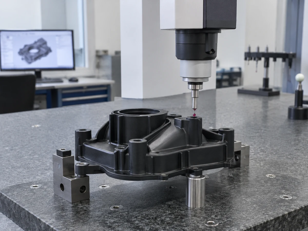
Confirm exact grade, stock identification and agreed traceability records. Review any supplier declarations required for the application rather than inferring them from color or appearance.
Check drawing revision, units, material, datums, tolerances and notes. Resolve contradictions between CAD and drawing before quotation or production.
Review critical features and assembled relationships on an initial part where agreed. Record the relevant measurement conditions and resolve deviations before repeating the route.
Monitor selected features at useful stages. Check parts after release or after joining when temporary clamping or heat could mask final variation.
Check mating holes, cover alignment, joint access and functional clearance against the agreed fixtures, mating parts or acceptance criteria.
Review joint continuity, alignment and visual condition. Agree leakage, strength or other functional testing where service demands it; a visual check alone does not prove performance.
Compare clarity, edge finish, scratches, burrs and joint appearance with an agreed sample or written criteria. Define cosmetic surfaces separately from hidden faces.
Verify required finished dimensions and assembled datums in the agreed state. Confirm reporting scope and sampling rather than assuming every feature receives a full report.
Protect transparent surfaces, thin edges and joints; separate parts and identify revisions where agreed. Shipment inspection and packaging records are included only when specified.
The images on this page are AI-generated process and component illustrations. They are not records of a TOPS factory inspection or customer shipment. Project-specific QC photos, inspection reports and manufacturing documentation should be requested and agreed in the quotation.
CNC machining is one form of plastic fabrication. Fabrication can include machining plus cutting, forming, joining, finishing and assembly; the terms describe different levels of manufacturing scope.
| Factor | Plastic Fabrication | CNC Machining |
|---|---|---|
| Meaning | Broad group of stock-to-part and assembly processes. | A specific subtractive manufacturing process family. |
| Processes | Cutting, machining, bending, bonding, compatible welding, forming and finishing. | Milling, turning, drilling, tapping and related cutting operations. |
| Typical starting material | Sheet, rod, tube or block, sometimes several materials in an assembly. | Rod, plate or block stock suitable for the specified geometry. |
| Best for | Guards, enclosures, panels, assemblies and customized structures. | Precision bores, pockets, threads, contours and component interfaces. |
| Multi-process parts | Coordinates several operations and assembled acceptance. | Can provide machined features within a larger fabrication route. |
| Tight tolerances | Depend on operation, joining and final assembly. | Generally strongest option for local precision features, subject to review. |
| Prototypes | Useful for complete part and assembly evaluation. | Useful for representative machined features without an injection mold. |
Request a fabrication quote when the deliverable is an assembled enclosure or a part requiring several operations. Request a machining review when controlled geometry is the main requirement. Either way, include final use and acceptance criteria so the proposed route delivers the required result.
Explore CNC plastic machining capabilities →Use a drawing-based discussion to align manufacturing scope, material, inspection and assembly before ordering. These are the practical areas we review with customers.
Coordinate the required operations in a single process plan. Confirm included steps, dependencies and any specialist scope so responsibilities are clear.
Review prismatic, rotational and multi-axis features through dedicated machining capabilities. Choose tooling and setups for geometry rather than for a marketing label.
Compare grades against the real thermal, chemical and mechanical environment. Discuss stock and substitutions before committing to a manufacturing method.
Work from a controlled CAD model and annotated drawing. Clarify revision, units and critical requirements so the finished part has defined acceptance criteria.
Discuss access, joints, support, radii and practical tolerances. Proposed changes require customer approval when they affect fit, function or drawing requirements.
Separate prototype objectives from repeat demand. Review how fixture and inspection requirements change as the design and order quantities mature.
Agree dimensions, joints, appearance and test scope before production. Identify required records and the conditions used to accept the finished assembly.
Use one coordinated quotation and communication route for the agreed deliverable. Confirm the actual included manufacturing and documentation scope rather than assuming every operation is automatic.
A typical nine-step workflow connects your drawings to the finished assembly. Operations, approval points and delivery terms are confirmed for the actual project.
Send the current 3D model and annotated drawing. Include material, quantity, units and any existing assembly or acceptance information.
Review functional interfaces, manufacturability, tool access and incomplete specifications. Resolve assumptions before the manufacturing scope is finalized.
Confirm grade, stock form, fillers, service conditions and required records. Customer approval controls substitutions.
Choose the cutting, machining, forming, joining and finishing sequence. Define fixtures and where critical dimensions will be verified.
Prepare stock and create drawing-defined profiles, pockets, holes and interfaces with suitable support and material-specific controls.
Perform the agreed applicable operations, or use mechanical fastening where selected. Control alignment and inspect after curing or cooling as needed.
Deburr and finish designated surfaces, install agreed hardware and assemble parts in the planned sequence.
Check dimensions, appearance, fit and specified functional requirements. Review and document results according to the agreed inspection plan.
Protect parts for handling and shipment. Confirm identification, packaging, delivery destination and required documents before dispatch.
Direct answers to common fabrication, material, assembly and quotation questions.
Plastic fabrication converts plastic stock into parts or assemblies using cutting, machining, forming, joining and finishing. The selected operations depend on material, geometry, quantity and the required finished result.
TOPS reviews custom projects involving CNC machining, cutting, drilling, suitable bending, bonding, finishing and assembly. Welding, specialist forming, laser cutting and other material-dependent operations are confirmed as part of the project scope rather than assumed for every plastic.
Many engineering plastics can be fabricated, including PEEK, POM, PTFE, Nylon, UHMW, PC, PMMA, PVC, PP and PVDF. The exact grade determines which operations are appropriate; additional materials such as ABS, HDPE, PETG, PEI, PPS and PAI require stock and process review.
CNC machining is one process family within plastic fabrication. Fabrication can also include profile cutting, bending, joining, polishing and assembly, while machining concentrates on subtractive creation of precise features.
Yes, many stock-based machined or fabricated parts do not need an injection mold. Dedicated fixtures or forming tools may still be required, and some forming routes have their own tooling costs.
Drawing-based candidates include guards, enclosures, housings, panels, covers, manifolds, trays, fixtures, jigs, brackets, windows, assemblies, bushings, rollers and insulators. Material suitability and acceptance requirements are reviewed before confirming manufacture.
Yes, prototypes and low-volume projects can be reviewed alongside repeat-production demand. Define whether the sample must validate fit, appearance, joining or functional performance so the chosen material and process are representative.
You can send STEP / STP, IGES / IGS, X_T, DWG, DXF, PDF or ZIP files. A CAD model defines geometry; an annotated 2D drawing should identify critical dimensions, material and acceptance notes. Combined uploads are limited to 10 MB.
We compare the required geometry, exact grade, joint loads, finish and final tolerance requirements. Machining suits controlled features, bending suits suitable sheet geometry, and bonding or welding requires compatible materials and a defined joint plan.
Yes, a part or assembly can combine cutting, machining, forming, joining, finishing and assembly. Sequencing and inspection must account for thermal distortion, joint alignment and cumulative dimensions.
YOUR DRAWING. YOUR FABRICATION PLAN.
Upload your CAD model or engineering drawing and include the plastic material, quantity, dimensions, tolerances, finish requirements and application information. Our team will review the project and recommend an appropriate fabrication process or process combination.
For assemblies, include joint details, mating parts, hardware, installation preparation and appearance requirements. Identify mandatory processes or tests, and explain which options may be discussed during DFM review. Company, name, email and phone are required; all project details and both uploads are optional.
info@tops-precision.comSTEP / STP / IGES / X_T / DWG / DXF / PDF or ZIP, maximum 10 MB. Larger files can be shared by email. Please agree confidential-file handling before sending sensitive drawings.