PVC / Vinyl
PVC and PVC-containing blends or films are excluded. Heating chlorine-containing plastic can release hazardous, corrosive fumes and damage equipment. Mechanical routing or machining is the alternative to review.

COMPATIBLE MATERIALS. CLEAN PROFILES.
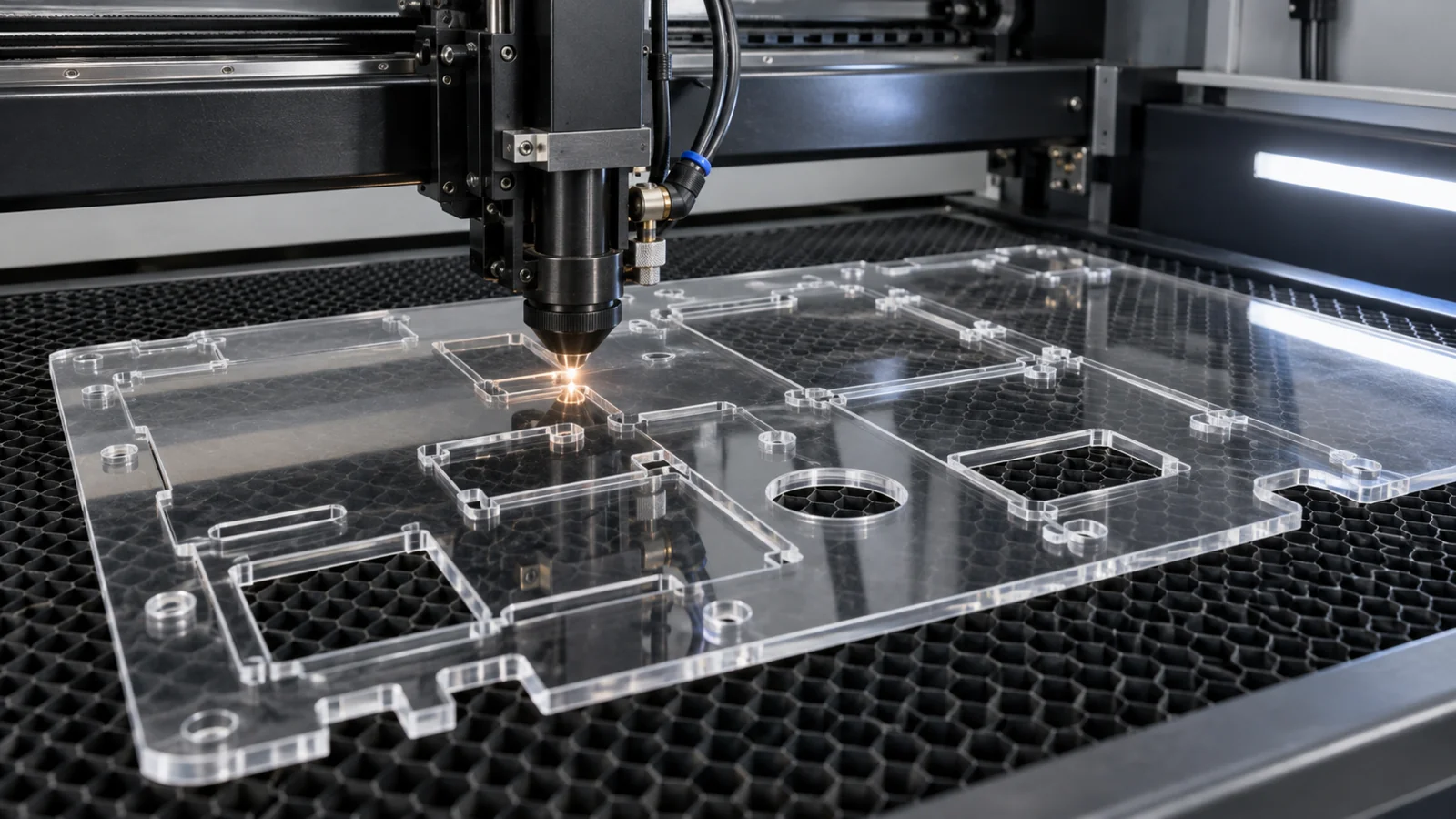
TOPS Plastics provides precision laser cutting for compatible plastic sheet materials, with particular expertise in Acrylic / PMMA. We manufacture custom panels, covers, windows, profiles, inserts and other flat plastic components from vector files and engineering drawings. Material, thickness, edge quality and fit requirements determine the process.
From a flat sheet to a finished component.
01
A drawing-based service for compatible sheet plastics. We confirm the material and process window before quotation; thickness range, sheet capacity and tolerance are reviewed for each project.
| Capability | TOPS Plastics |
|---|---|
| Process | CO₂ laser cutting where the material and application are suitable. |
| Best material | Acrylic / PMMA; cast or extruded stock selected against finish and thickness requirements. |
| Geometry | Flat 2D profiles, through holes, slots, mounting patterns and internal cutouts. |
| Additional operations | Engraving, marking, polishing and secondary machining where applicable. |
| Input files | DXF, DWG, AI and vector PDF, supported by a dimensioned engineering drawing. |
| Production | Prototypes, low-volume batches and repeat production. |
| Inspection | Dimensional and visual checks to agreed acceptance criteria. |
| Alternative process | CNC routing or milling when laser cutting is unsuitable. |
02
Plastic laser cutting uses a focused laser beam to cut two-dimensional profiles from compatible plastic sheet without physical contact between a cutter and the part.
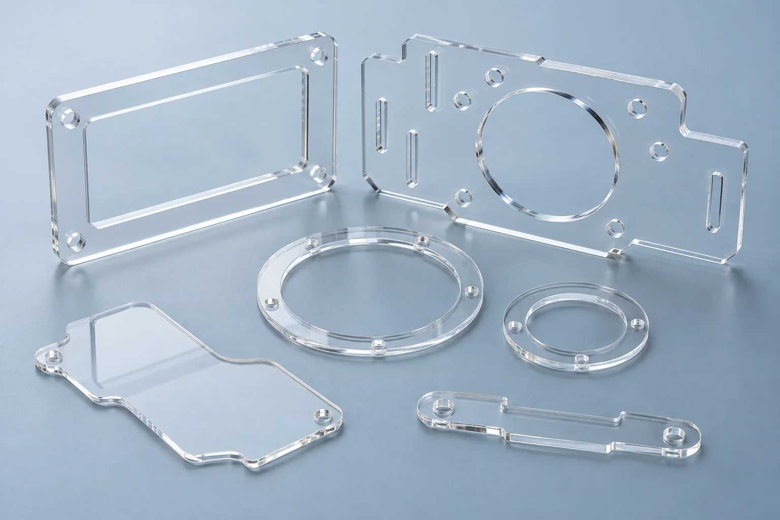
The beam follows a vector path and removes material along a narrow cut. For acrylic / PMMA, a suitable CO₂ process can leave a smooth, glossy edge, reducing the finishing needed on many windows, covers and panels. There is no dedicated profile tooling, making revisions practical during prototype development.
The process still introduces heat. Material grade, sheet thickness, focus, nesting and small-feature spacing affect the result. A glossy edge does not establish an optical specification or a precision fit. We assess the drawing and choose laser cutting, CNC routing or a combination according to the functional and cosmetic requirements.
03
A polymer name alone is insufficient. Grade, additives, protective film, thickness, extraction requirements and acceptance criteria must be checked before a material is approved.
| Material | Laser suitability | Recommended approach |
|---|---|---|
| Acrylic / PMMA | Preferred candidate | Review cast or extruded grade, thickness, engraving and edge finish. |
| POM / Acetal | Possible only after process review | Evaluate decomposition products, extraction, edge quality and dimensional needs; CNC remains an alternative. |
| PET / PETG | Process dependent | Identify the exact sheet material; test melting, edge condition and dimensional response. |
| Polypropylene | Limited for many sheet parts | Heat can cause melting or distortion; CNC routing is often preferable. |
| HDPE / PE | Limited for many sheet parts | Review melting and edge quality; routing or machining usually provides a better industrial route. |
| Polycarbonate | Generally poor for thicker industrial sheet | Prefer CNC routing or milling for functional panels and guards; thin films are a different application. |
| ABS | Not preferred for this service | CNC machining is usually better for dimensional features and industrial edges. |
| PTFE / Teflon | Excluded from conventional laser processing | Use CNC machining; do not treat fluoropolymers as generic laser-cut plastics. |
| PVC / Vinyl | Excluded from conventional laser processing | Use an appropriate mechanical cutting process; verify blends and surface films. |
Material approval includes the complete stock construction: coatings, adhesives and masking can change processing suitability. We do not accept unidentified sheet as acrylic based on appearance.
Explore Acrylic / PMMA →04
Confirm the material before selecting the machine. A test cut does not replace material identification or a suitable process and extraction assessment.
PVC and PVC-containing blends or films are excluded. Heating chlorine-containing plastic can release hazardous, corrosive fumes and damage equipment. Mechanical routing or machining is the alternative to review.
Do not laser cut until the polymer, grade, additives and coatings are positively identified. Provide supplier documentation or a material designation with your drawing.
CNC routing or milling is normally preferred for industrial sheet components. Laser heat can discolor or damage the edge, especially in thicker stock; thin-film applications need a separate assessment.
Excluded from conventional laser cutting because thermal decomposition can create hazardous fluorinated products. Specify the PTFE grade for a CNC machining review.
Other filled, flame-retardant or multilayer materials also require assessment. Compatibility with laser marking does not automatically mean compatibility with through cutting.
05
Choose the operation around the drawing. Flat profile cutting, shallow engraving and secondary CNC features have different acceptance requirements.
Clear panels, covers, windows, brackets, profiles, display components and light-guide shapes from suitable sheet. State load, transparency and edge expectations before manufacture.
Outer contours, internal cutouts, slots, mounting patterns and irregular shapes produced from released vector geometry. Review small features and kerf-sensitive fits.
Part numbers, logos, scales, identification and panel markings on approved material. Agree position, depth, contrast and artwork before production.
Direct-from-CAD flat parts without dedicated mold or profile tooling. Check shape, assembly clearance and cosmetic appearance before releasing a batch.
Controlled vector files, nesting and inspection criteria for recurring orders. Sheet utilization is balanced against part spacing, heat accumulation and handling.
06
Acrylic is the leading material choice for this service because it combines transparent sheet availability with useful CO₂ cutting and engraving behavior.
Suitable acrylic stock and settings can produce smooth, glossy edges. Surface appearance is agreed separately from dimensional acceptance.
Contactless cutting avoids cutter pressure on delicate profiles, although support and thermal distortion still need attention.
Vector paths support intricate contours and internal openings without selecting a physical cutter for every profile.
Compatible parts can share a sheet layout. Spacing and cutting order must prevent excessive local heating.
Shallow identification and graphics can be combined with the cut profile. Cast acrylic often gives a frosted engraved appearance.
A released CAD path supports prototypes and small batches without a dedicated die or mold.
Cast and extruded acrylic are not interchangeable by default. Cast sheet is often selected for engraving appearance; extruded sheet can offer useful thickness consistency. We review the actual supplier grade, dimensional requirement and intended finish. Laser-cut edges can retain residual stress: bonding, solvent exposure or later polishing should be evaluated before the manufacturing route is released.
Review acrylic fabrication options →07
Laser-cut tolerance depends on material, sheet thickness, geometry, feature size, beam kerf, heat input and the dimensional requirement of the drawing.
| Feature | Main consideration |
|---|---|
| Outer profile | Kerf compensation and thermal behavior determine the finished boundary. |
| Small holes | Review hole diameter relative to thickness, circularity and local heat. |
| Narrow slots | Heat accumulation can affect width and nearby thin sections. |
| Long straight profiles | Sheet flatness, support and temperature affect consistency. |
| Acrylic windows | Check dimensions together with edge appearance and surface protection. |
| Fit-critical holes | CNC drilling, boring or finishing may be preferable. |
| Thick sheet | Review cut taper, heat effects and edge condition. |
| Cosmetic parts | Define scratches, discoloration, masking and handling acceptance. |
We do not apply a single tolerance to every profile, hole and thickness. Identify the critical features and datums on a drawing. Where a fit cannot be reliably achieved by laser alone, agree a secondary machining operation and inspection method.
Send your drawing for a laser cutting feasibility review →08
Kerf is the narrow width of material removed by the beam. Its width and the heat input influence profile size, hole dimensions and edge condition, particularly on small features and thicker sheet.
Offset the production path to suit the measured process. Provide nominal finished geometry rather than silently adding your own kerf allowance to the design.
Excessive local heat can melt, discolor or distort plastic. Material selection, cut sequence and feature spacing must be considered together.
Very small holes, pointed corners and narrow bridges may not reproduce cleanly. Review minimum features for the actual thickness and grade.
Warped stock changes focus and the relationship to the support bed. Assess sheet condition before cutting and inspect in the agreed state.
A sample coupon or first article can establish whether the proposed edge, fit and small features are acceptable. It does not justify a universal minimum hole size or kerf value across different plastics.
09
Use laser for compatible flat profiles when the cut edge and tolerance meet the application. Choose CNC for pockets, controlled depths, threads, precision bores or materials that do not suit laser processing.
| Factor | Laser cutting | CNC routing / milling |
|---|---|---|
| Best geometry | Flat 2D through profiles | 2D profiles plus controlled-depth and 3D features |
| Tool contact | Contactless beam | Physical cutting tool; support and clamping required |
| Acrylic edge | Often glossy with suitable material and settings | Machined edge; polishing can be added |
| Pockets | Not a precision pocket-machining process | Controlled-depth pockets |
| Counterbores | Not produced by ordinary through cutting | Controlled diameter and depth |
| Threads | Not produced by ordinary profile cutting | Tapping or thread milling where suitable |
| Tight-fit holes | Process-dependent; heat and kerf matter | Usually the better route for controlled bores |
| Thick material | Limited by material and qualified process | Often more suitable; tool access and support still matter |
| Acrylic sheet profiles | Strong candidate | Strong candidate with a different edge finish |
| Polycarbonate sheet | Normally not preferred for this service | Preferred industrial route |
| PVC | Excluded from conventional laser processing | Mechanical process selected with suitable controls |
| Complex machined parts | Limited to flat profile contribution | Preferred for multi-feature components |
10
Drawing-based sheet components for equipment and assemblies. Material compatibility, loads and regulatory requirements are reviewed for the intended use.
Flat equipment panels with mounting holes, slots and cutouts.
Viewing windows with defined dimensions, edge finish and protected cosmetic faces.
Flat protective covers sized to an assembly drawing.
Viewing panels where the selected material meets the risk assessment; impact-critical guards may require CNC-cut polycarbonate.
Apertures and identification for switches, displays and instruments.
Industrial display windows, overlays and transparent support shapes.
Custom flat light-guide shapes; optical performance and surface finish require separate validation.
Compatible sheet plates with specified markings and mounting patterns.
Flat shaped inserts and interface pieces.
Irregular contours produced from controlled vector geometry.
Only in an approved laser-compatible material that also meets sealing, load and environment requirements.
Early parts for layout, assembly and appearance review.
11
Send a dimensioned drawing together with clean vector geometry. The drawing should define finished dimensions and which surfaces matter in the assembly.
DXF, DWG, AI or vector PDF are preferred. State units and scale; remove duplicate or open cut paths and separate engraving artwork from through-cut geometry.
Small holes are sensitive to kerf, taper and local heat. Mark critical hole sizes so CNC finishing can be assessed.
Allow space between openings and neighboring parts. Dense details can concentrate heat and change edge quality.
Thin webs can soften, distort or break during handling. Review the bridge width against material and thickness.
Identify viewing faces, masking requirements, allowable scratches and optical acceptance. Appearance on one face may differ from the other.
State as-cut, glossy, matte, mechanically polished or CNC-finished edges. Identify edges that will be bonded or exposed to solvents.
Mark pockets, counterbores, threads and critical bores clearly, including datums and controlled depths. The vector profile alone cannot define these features.
Include the nominal sheet thickness and grade in the drawing or file package. Overall size, tolerances, revision and quantity help us review nesting and process feasibility. Raster artwork can support a marking discussion but does not replace an accurate vector cut path.
12
Add part numbers, serial information, measurement scales, logos, warning text, panel graphics and identification on approved sheet material.
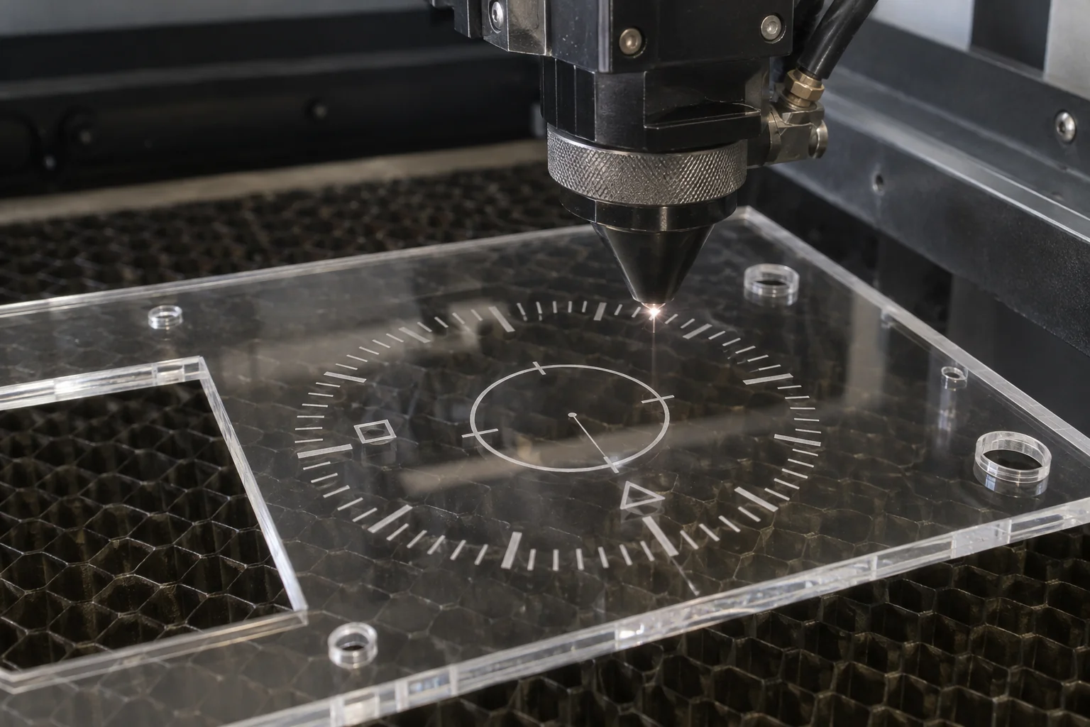
Provide artwork, location, orientation and revision. Agree contrast and depth on the actual material.
Locate markings away from critical fits or optical regions unless the drawing specifies otherwise.
Review a sample where readability, cosmetic contrast or repeat identification matters.
Engraving is shallow surface marking rather than deep precision machining. A deep pocket, controlled bearing seat or sealing groove belongs in the CNC machining review. Engraving compatibility and through-cut compatibility are assessed separately.
13
The appropriate finish depends on whether the edge is cosmetic, functional, bonded or exposed to a chemical environment.
| Edge / finish | Best use and review point |
|---|---|
| Laser-Cut Acrylic Edge | Glossy profile edges where the as-cut result meets the agreed appearance. |
| As-Cut Functional Edge | Internal components where dimensional and handling acceptance are sufficient. |
| Mechanical Polish | Enhanced cosmetic appearance; account for material removal and edge rounding. |
| Flame Polish | Selected acrylic cosmetic edges only after review of residual stress, bonding and service environment. |
| CNC Finish | Mating faces and fit-critical edges that need a controlled machined feature. |
Polishing is not an automatic solution for every transparent part. Define acceptable edge rounding, dimensional change and visual appearance before choosing a finish. Stress-sensitive bonding and solvent service may call for a different sequence or material treatment.
14
A flat outer profile can be laser cut while CNC machining produces precision secondary features. The combined route is reviewed against setup cost, heat effects, datums and the final inspection requirement.
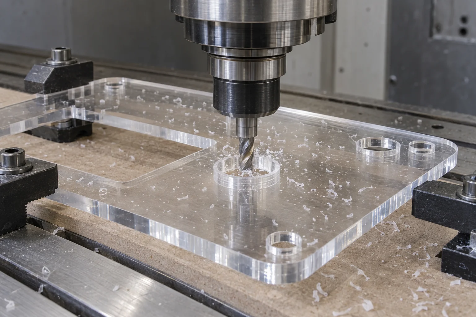
Confirm acrylic sheet and thickness
Laser cut the outer profile
CNC mill pockets and counterbores
Drill or tap specified holes
Polish or engrave where required
Inspect finished features and appearance
Control panels, machine covers, inspection windows, housings and equipment panels can benefit from this approach. Allowance, workholding and feature location must be planned so the second operation relates correctly to the finished profile.
A combined route is not automatically cheaper. For a small quantity of tightly toleranced parts, machining the whole component may be more efficient. We compare the complete drawing rather than judging the outer contour alone.
Explore plastic fabrication →15
Develop the first part around fit and appearance, then release a stable file set and acceptance criteria for production.
Validate the profile, assembly fit, appearance and hole positions. Use an approved sample to resolve edge or engraving questions.
Equipment panels and customized components in small batches. Balance nesting, setup, handling and secondary operations.
Control vector revision, grade, thickness, nesting strategy and inspection standards. Review changes before the next order.
16
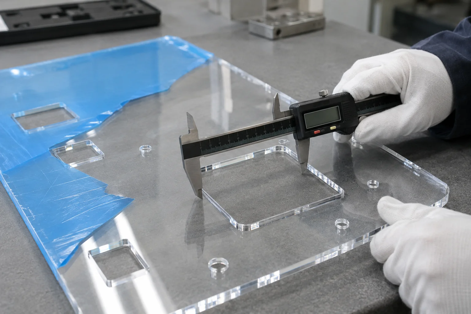
Dimensional checks and visual acceptance work together. A part can match its profile dimensions and still fail on scratches, edge condition or discoloration.
Verify material and sheet construction
Review vector files and drawing revision
Test cut if required
Inspect the first article
Cut the production batch
Check profiles, holes and slots
Inspect edges and cosmetic faces
Complete secondary machining if required
Perform final inspection
Protect and package the parts
The inspection plan can include outer profile, hole size, feature position, slot width, taper and critical mating dimensions. Agree how flexible sheet is supported during measurement and whether protective masking remains in place.
Visual inspection includes edge quality, burn marks or discoloration, scratches and protective-film condition. Final acceptance follows all secondary operations; inspection before machining or polishing alone does not establish finished-part conformity.
17
Select the polymer for its working environment first. Laser suitability alone does not establish impact protection, electrical compliance, optical performance or medical acceptance.
Viewing windows, covers and control panels with defined mounting features.
Protective covers and viewing panels; assess impact and guard requirements separately.
Instrument panels and compatible insulating flat parts to the specified material and electrical requirements.
Instrument windows and transparent components; grade, cleaning and applicable approvals require project review.
Diffusers, light-guide profiles and transparent components with validated optical requirements.
Panels, covers and identification plates supplied to a released drawing.
Flat parts for rapid layout, fit and appearance verification.
18
We evaluate material, thickness, geometry, tolerance and edge requirements first, then choose laser cutting, CNC routing or a combined process based on the drawing.
Review how the polymer responds to heat and mechanical cutting.
Consider grade, thickness, transparency, engraving and edge acceptance together.
Plan the profile and secondary features as one finished component.
Check identified stock, coatings and films before the cutting route is accepted.
Carry approved geometry and acceptance criteria into recurring batches.
Use controlled revisions, dimensions and vector files.
Inspect functional features and transparent cosmetic faces.
Review machining, polishing, marking and assembly needs in the quotation.
19
A controlled sequence connects your vector file to the finished component. Optional operations are confirmed for the project rather than assumed for every part.
Upload drawing and vector file
Confirm material and grade
Review laser compatibility
Confirm thickness and edge requirements
Review design and kerf strategy
Test cut or first article if required
Laser cut and engrave
Add CNC secondary operations if required
Complete edge and cosmetic finishing
Inspect the finished part
Apply protective packaging
20
Acrylic / PMMA is the preferred material for this service. Other identified plastics, such as selected POM or PET sheet, require a grade-specific process review. PVC, PTFE and unidentified plastics are excluded from conventional laser cutting.
Acrylic / PMMA is usually the strongest choice for transparent flat parts with a glossy cut edge. Cast versus extruded stock is selected around engraving, thickness consistency and the drawing requirements.
Yes. Compatible cast and extruded acrylic can be CO₂ laser cut into panels, windows and profiles. Sheet thickness, small features, edge appearance and residual stress must still be reviewed.
Some thin films can be processed with suitable laser systems, but that does not make industrial sheet a preferred candidate. For thicker functional panels and guards, CNC routing or milling is normally the better route because of thermal edge damage and discoloration.
PVC should not be processed as a conventional laser-cut plastic. Heating chlorine-containing material can create hazardous, corrosive fumes. PVC blends, coatings and films are also subject to material verification; consider mechanical machining instead.
Neither process is universally more accurate. Kerf, heat, thickness and geometry affect laser profiles. CNC machining is usually preferred for tight-fit bores, pockets, threads and features tied to functional datums. Confirm the requirement on the drawing.
A suitable acrylic and CO₂ process can leave a smooth, glossy edge. It is not automatically an optical-quality or stress-free finish. Agree the appearance, dimensions and any bonding or solvent-service requirements.
Send DXF, DWG, AI or vector PDF with a dimensioned drawing, units, thickness, grade and revision. Use the supported upload formats or put AI and related files in a ZIP package. A raster picture alone does not define a precise cut path.
Yes, where the combined route is suitable. The profile may be laser cut before CNC pockets, counterbores, drilling or tapping. Allowances, datums, workholding and final inspection must be planned together.
Yes, for compatible sheet parts. Direct vector processing avoids dedicated profile tooling and supports revisions. Prototype approval should cover fit, holes, appearance and secondary operations before production.
YOUR DRAWING. THE RIGHT PROCESS.
Upload your DXF, DWG, AI, vector PDF or engineering drawing and identify the material, sheet thickness, quantity, critical dimensions, edge requirements and secondary machining needs. Our team can review whether laser cutting, CNC routing or a combined process fits your component.
Keep the form simple: company, name, email and phone are required. Country, part number, quantity and drawing upload are optional. Put material, thickness, cosmetic-face, engraving and machining details in the drawing or ZIP package. AI files can be included in ZIP; larger packages can be shared by email.
info@tops-precision.comDXF / DWG / PDF / STEP / STP / IGES / X_T or ZIP, maximum 10 MB. Include AI files in ZIP. Larger packages can be shared by email. Agree confidential-file handling before sending sensitive drawings.