Solvent Bonding
For compatible Acrylic / PMMA, PVC and selected ABS assemblies. Close fit, clean edges, controlled capillary gaps, accurate fixtures and sufficient stabilization time govern the result.

ENGINEERED JOINTS. COMPLETE ASSEMBLIES.
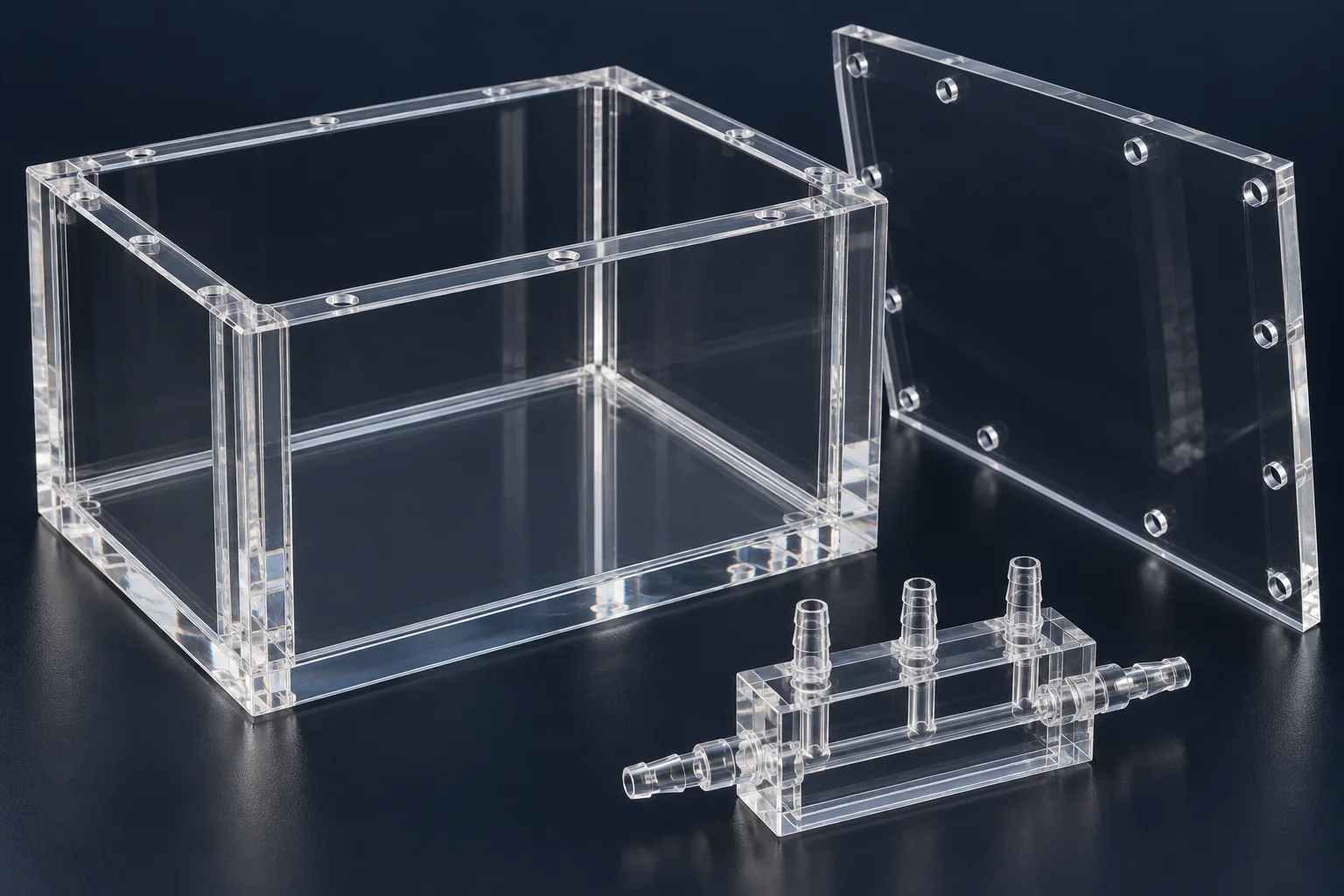
TOPS Plastics provides custom plastic bonding and assembly for fabricated components, housings, enclosures, manifolds, covers and transparent assemblies. We select the joining method around your plastic materials, joint geometry, strength, appearance, chemical exposure and production volume.
Separate components. One considered assembly.
01
A bonded assembly starts with the material pair, the joint and the conditions in which it must work. We review these together before choosing a joining route.
| Capability | Project scope |
|---|---|
| Joining methods | Solvent bonding, structural adhesives, UV-curing adhesives and mechanical or hybrid joining, subject to substrate and application review. |
| Materials | Acrylic / PMMA, Polycarbonate, PVC, ABS, PETG and other selected compatible plastics. Exact grades and additives matter. |
| Applications | Custom housings, enclosures, manifolds, machine guards, equipment covers and transparent chambers. |
| Joint requirements | Structural load transfer, sealing, cosmetic appearance or optical clarity, with agreed acceptance criteria. |
| Production | Prototype assemblies, low-volume builds and repeat production with a defined assembly sequence. |
| Project inputs | Assembly drawings, CAD files, individual part drawings, samples and service conditions. |
| Secondary operations | CNC machining, routing, cutting, selected polishing and component assembly as the design requires. |
| Inspection | Visual and dimensional checks; fit, leak or functional checks when specified and agreed. |
02
Plastic bonding joins separate components into a finished assembly using a compatible solvent or adhesive system. The best method depends on the polymer, joint design and required performance.
Solvent bonding softens compatible thermoplastic surfaces so that the joint can fuse as the solvent leaves. It depends on material compatibility, intimate fit and a controlled application process; it is not a universal method for all plastics.
Adhesive bonding creates a separate cured layer between substrates. This can support gap filling or dissimilar-material joining when the adhesive chemistry, surface preparation and cure are appropriate.
Plastic welding is a related but different process: it joins compatible thermoplastics through heat or other energy. Mechanical fasteners can also form part of an assembly when a removable joint or an alternative load path is needed.
03
Material compatibility comes first. We then assess loading, sealing, appearance, access, assembly time and the operating environment.
| Your requirement | Route to evaluate | What must be checked |
|---|---|---|
| Clear acrylic assembly | Controlled solvent bonding or a compatible UV-curing adhesive | Edge condition, fit, bubbles, haze and residual stress. |
| Structural opaque assembly | Selected structural adhesive | Actual substrate grades, joint area, peel loads and cure conditions. |
| PVC chemical-service component | Compatible solvent cement or a qualified welding process | PVC grade, chemical exposure, joint geometry and service rating. |
| Serviceable assembly | Mechanical fasteners or hybrid joining | Removal access, plastic creep, inserts and sealing strategy. |
| PP or HDPE component | Specialty adhesive with qualified preparation, welding or fastening | Low surface energy, treatment durability and service testing. |
| Dissimilar materials | Compatibility-tested adhesive | Thermal expansion mismatch, stiffness and chemical resistance. |
| Leak-tight assembly | Engineered solvent, welded or adhesive joint | Joint continuity and an agreed leak test; appearance alone is insufficient. |
| Cosmetic transparent joint | UV adhesive or controlled solvent bonding | Light transmission, visible bond line and cosmetic acceptance. |
04
We select a joining system for the assembly rather than choosing one adhesive for every plastic.
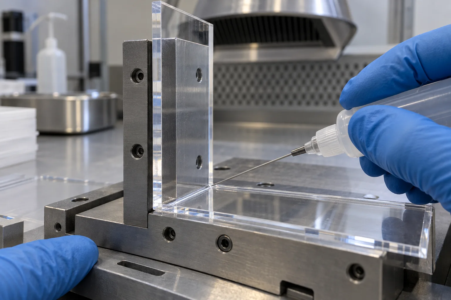
For compatible Acrylic / PMMA, PVC and selected ABS assemblies. Close fit, clean edges, controlled capillary gaps, accurate fixtures and sufficient stabilization time govern the result.
For selected structural, gap-filling or dissimilar-material joints. Epoxy, polyurethane, acrylic and specialty systems offer different stiffness, impact and chemical behavior; each needs substrate-specific review.
For compatible transparent and cosmetic assemblies where curing light can reach the adhesive. Wavelength, substrate transmission, bond depth and shadowed areas determine the cure strategy.
For removable assemblies, difficult-to-bond substrates or load paths that benefit from fasteners. A hybrid joint can combine fastening with adhesive or a separate sealing system.
The proposed adhesive, solvent, preparation method and cure schedule are confirmed for your particular materials. Process availability and any special treatment or test requirements are agreed before production.
05
The following is a general selection guide, not a bond-strength guarantee. Grade, fillers, coatings, contamination and service conditions can change the result.
| Plastic | General bonding difficulty | Methods and considerations |
|---|---|---|
| Acrylic / PMMA | Often comparatively easy | Compatible solvent or UV adhesive; protect optical surfaces and manage machining stress. |
| ABS | Often comparatively easy | Selected solvent or adhesive systems; check formulation and appearance. |
| PVC | Often comparatively easy | Compatible solvent cement or welding; confirm rigid/flexible grade and chemical service. |
| PETG | Often manageable | Selected solvent or adhesive systems; confirm stress-cracking and cosmetic compatibility. |
| Polycarbonate | Requires care | Selected adhesives or qualified solvent systems; environmental stress cracking is a key concern. |
| Nylon | Requires care | Grade, moisture conditioning, preparation and adhesive compatibility affect adhesion. |
| Delrin / POM | Difficult | Chemically resistant surface; specialty preparation and adhesive qualification may be necessary. |
| HDPE | Difficult | Low surface energy; evaluate specialty adhesives, qualified treatment, welding or fastening. |
| Polypropylene / PP | Difficult | Low surface energy; standard general-purpose adhesives may not wet or adhere reliably. |
| PTFE / Teflon | Very difficult | Extremely low surface energy; specialized treatment and qualification, or a different joining design. |
06
These materials can be useful precisely because they resist adhesion or chemicals. That same behavior makes a dependable bonded joint more demanding.
Low surface energy limits wetting by many ordinary adhesives. A specialty system or qualified activation process may be needed.
Its low-energy surface and flexibility require careful adhesive selection and a joint that accommodates movement.
Chemical resistance and its surface chemistry make general-purpose adhesive bonding difficult. Do not assume an adhesive that works on ABS will work on POM.
Very low surface energy makes it particularly hard to bond. Specialized surface treatment may be necessary and must be validated for the application.
Plasma, corona, flame treatment, chemical treatment and primers are possible preparation routes for selected substrates. They are not interchangeable, and their availability, process control and durability must be confirmed. We do not treat them as automatic solutions or assume a treatment capability without project review.
For some PP and HDPE assemblies, compatible thermoplastic welding or mechanical retention is the more practical route. Specialty adhesives can bond some grades without special activation, but supplier data and tests on the actual parts remain essential.
07
A clean-looking surface can still carry release agent, machining coolant, oil or fingerprints. A strong adhesive cannot compensate for an unsuitable interface.
Identify both polymer grades, fillers, coatings and any protective film.
Inspect the mating surfaces for damage, contamination and residual stress.
Clean using a method compatible with the plastic and adhesive system.
Prepare the joint surfaces only as the selected process requires.
Apply a specified primer or qualified treatment where needed.
Dispense the solvent or adhesive with controlled quantity and coverage.
Fixture the assembly and maintain the agreed cure or stabilization conditions.
Inspect the completed joint and keep the required process records.
Dust, grease and release agents can prevent wetting. Coolant residue, fingerprints, inconsistent roughness and retained cleaning fluid can also compromise adhesion or appearance. Handling after preparation must keep the bonding surfaces clean.
Abrasion and solvent wiping are not universal instructions. Abrading a transparent surface can spoil appearance, while an incompatible solvent can craze or crack Polycarbonate and other stressed plastics. Use substrate-specific supplier guidance and qualified trials.
08
Joint geometry should spread load through a useful bonding area and reduce peel, cleavage and locked-in stress. Review the joint before machining the individual parts.
Lap joints and supported overlaps often distribute load better than a small butt joint. More area helps only when the adhesive wets and cures throughout the joint.
Design the load path to favor distributed shear or compression. Unsupported edges can concentrate stress and start a joint opening.
Use the gap required by the selected system. A solvent capillary joint and a gap-filling structural adhesive need different fits.
Shoulders, rebates, tabs and locating features can control position and reduce dependence on clamp force. Keep them compatible with the assembly sequence.
Do not pull distorted parts together and trap stress in the joint. Allow for tolerances, thermal movement and cure shrinkage.
Give trapped air and excess material a controlled escape path. Plan dispensing, inspection and curing access, especially in enclosed channels.
Use suitable transitions and support near joints. Sharp corners, abrupt section changes and local loads can weaken an otherwise sound assembly.
Small bonding area; opening loads can concentrate at the interface.
Overlap spreads the load; design the gap and manage edge peel.
The diagrams show load-path concepts rather than approved dimensions. Bond overlap, gap, wall thickness and fixtures must be engineered for the actual materials and loads.
09
There is no single strongest glue for every assembly. Define what the joint has to do and how success will be measured.
Identify static, cyclic, impact and peel loads, load direction, stiffness and safety-related requirements. State whether a test specimen or assembled-part test is needed.
Specify the medium, pressure or vacuum, exposure time, temperature and permitted leakage. A visually continuous seam does not establish a pressure rating.
Define visible faces, acceptable bubbles, haze, squeeze-out and bond-line appearance. Agree a sample or visual acceptance standard when needed.
List chemicals, concentration, cleaning agents, exposure duration and continuous or peak temperatures. Assess both substrates and the cured joining system.
10
Transparent joints have two jobs: hold the assembly together and preserve the appearance that the application requires.
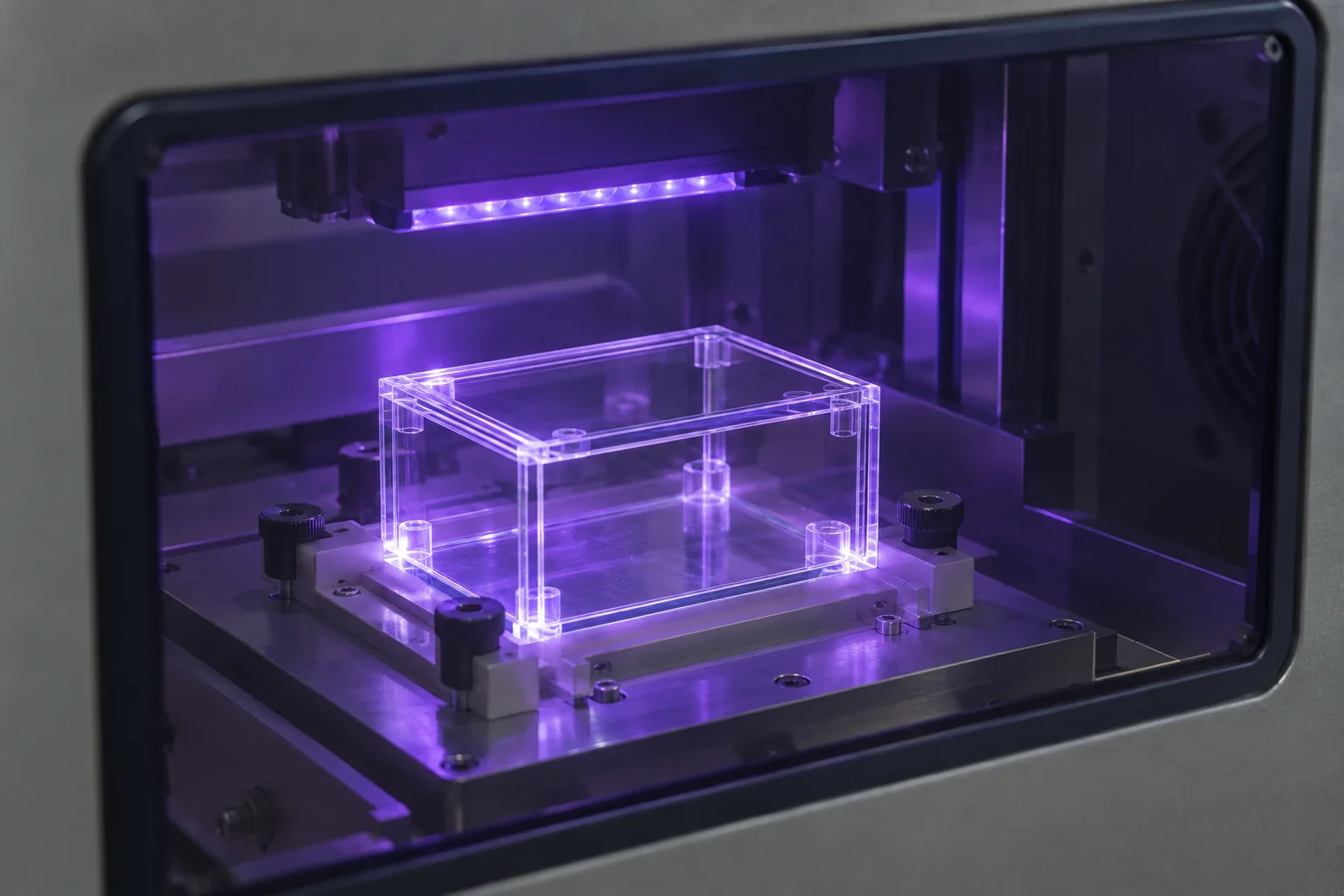
For compatible acrylic assemblies, edge preparation, fit, capillary flow and fixtures help form a clean seam. Excess solvent, poor fit or residual stress can cause bubbles, whitening or crazing.
For selected transparent assemblies, a controlled adhesive layer can provide a neat visible joint. Verify the actual material transmission at the curing wavelength and confirm cure in all joint regions.
Clear chambers, housings, equipment covers, instrument windows, display enclosures and selected clear manifolds need a defined cosmetic and functional specification.
Plan machining, laser cutting and polishing before bonding. These operations can leave stress or alter edge fit; use compatible handling, cleaning and packing.
Clear Polycarbonate is not interchangeable with Acrylic / PMMA. An acrylic solvent process can damage a Polycarbonate component. Dissimilar clear polymers require a compatible system and tests for crazing, haze and movement.
UV-blocking grades, coatings, thick sections and shadowed corners can prevent complete light cure. A secondary cure is possible only where the specific adhesive system supports it; visible transparency alone does not prove UV transmission.
Acrylic / PMMA material guide →11
We review multi-part assemblies from the individual component geometry through to the finished joint and handling requirements.
Clear equipment enclosures with controlled corner alignment and visible seam requirements.
Fabricated clear chambers with access, sealing and agreed service conditions.
Multi-piece housings combining machined features and joined panels.
Custom covers and protective panels with bonded brackets or locating features.
Selected multi-part flow components with defined channel geometry and leak criteria.
Transparent guards and protective assemblies with mounting and service-access requirements.
Custom holders, chambers and equipment components made to the specified materials.
Selected assemblies reviewed against media, pressure, temperature and cleaning conditions.
Transparent windows and frames with agreed optical and cosmetic acceptance.
Precision components assembled with defined datum and fit relationships.
Fabricated containers with engineered corner joints and handling requirements.
Machined plates, brackets and housings joined into a finished component.
12
Compare the full assembly requirement, including material compatibility, repair access, appearance and the operating environment.
| Joining method | Where it can fit | Main limitations |
|---|---|---|
| Solvent bonding | Close-fitting compatible thermoplastics, including selected acrylic or PVC assemblies. | Material-specific; fit, solvent compatibility, residual stress and stabilization matter. |
| Structural adhesive | Selected load-bearing, gap-filling and dissimilar-material joints. | Preparation, bond gap, adhesive properties and complete cure must be controlled. |
| UV adhesive | Compatible transparent assemblies with light access and cosmetic requirements. | Substrate transmission and shadowed bond areas can limit cure. |
| Plastic welding | Compatible thermoplastic assemblies, often considered for PP, PE or PVC. | Needs a suitable qualified process; heat, distortion and access can affect geometry. |
| Mechanical fastening | Removable joints, poor adhesive compatibility or direct mechanical retention. | Local stresses, creep, inserts, sealing and installation torque need attention. |
| Hybrid joining | Assemblies combining load transfer, sealing or positioning functions. | The roles of the adhesive, seal and fasteners must be clearly designed. |
13
Welding can be worth evaluating when a compatible thermoplastic joint is preferred over a separate adhesive layer, especially for selected PP, PE and PVC assemblies.
It may suit chemical-service or fabricated thermoplastic assemblies where the material, joint access and geometry support a qualified welding process. The substrate grades must be compatible, and heat input, joint preparation and distortion need control.
Welding is not automatically stronger or more leak-tight than bonding. Agree the available process, acceptance criteria and any required functional testing for the specific assembly. For mixed plastics, cosmetic transparent joints or heat-sensitive features, another method may be more appropriate.
Discuss the full plastic fabrication route →14
Sometimes, with a selected adhesive and a joint designed for both materials. Matching appearance does not establish chemical compatibility.
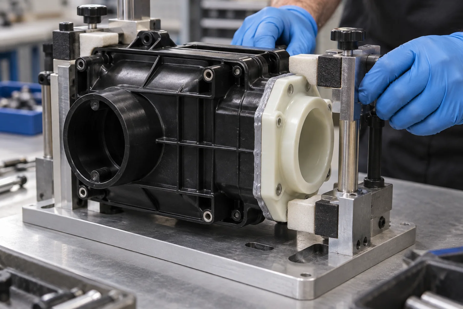
State both exact grades, coatings and fillers. Compatibility must cover each interface, not just one substrate.
Different thermal expansion and stiffness can create stress during temperature changes or loading. A suitable adhesive and gap may help accommodate it.
Cure shrinkage, heat, solvent exposure and fixture restraint can affect alignment, internal stress and appearance.
Assess the actual substrates with relevant chemicals, temperature cycles and loads. A room-temperature handling trial does not qualify long-term service.
15
Inspection follows an agreed plan covering the joint, the finished dimensions and the functions that matter for your application.
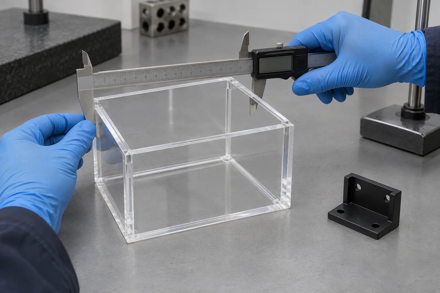
Review material identification, drawing revisions and joint requirements.
Verify surface preparation and handling before joining.
Check fixture location, alignment and component fit.
Control adhesive or solvent application and the specified cure conditions.
Inspect visible continuity, bubbles, voids and excess material.
Check dimensions, alignment, haze, cracks and crazing.
Perform agreed fit, leak or functional checks where required.
Record specified results and release the assembly against acceptance criteria.
Clean and protect joints and cosmetic surfaces for packing.
A visual check does not establish bond strength or service life. If strength, leak or functional testing is required, define the method, sample quantity, medium, pressure, duration, temperature and pass criteria before quotation.
A destructive test may require additional parts or representative coupons. Any laboratory testing, certification or special inspection must be specifically agreed; it is not implied by a standard assembly order.
16
The first build establishes a workable joint and assembly sequence. Repeat production needs a controlled process that preserves those decisions.
Review fit, appearance, sealing and joint geometry using actual materials. Use the results to refine component design and acceptance criteria.
Introduce repeatable fixtures, preparation instructions and a practical cure sequence. Plan handling and inspection around the batch quantity.
Control material identity, adhesive batch and shelf life, preparation, dispensing, fixture condition and cure. Keep the agreed traceability and inspection records.
17
Applications guide the joining specification. Industry use alone does not establish regulatory approval or suitability for a particular service.
Custom enclosures, holders and transparent assemblies. Define cleaning, contact and any required material documentation.
Covers, guards, housings and joined brackets designed for installation and maintenance.
Instrument housings, panels and insulating assemblies with defined temperature and compatibility requirements.
Selected channels, chambers and manifolds reviewed for media, leakage and operating conditions.
Custom guards, sensor housings and fixture components with alignment and movement requirements.
Transparent chambers and instrument components with agreed cleanliness, visibility and dimensional criteria.
18
Bring the part geometry and assembly requirement into the same drawing review. Our focus is a manufacturable joint and a clear acceptance plan.
Review the substrate grades and environment before choosing a joining method.
Coordinate component machining, cutting and assembly so mating features support the joint.
Consider optical faces, seam appearance and stress-sensitive clear plastics.
Define cleaning, handling and any selected primer or treatment requirements.
Assess overlap, gap, alignment, venting and the load path before production.
Use early builds to establish fixtures, sequence and repeatable process conditions.
Agree dimensions, visual acceptance and any special functional checks.
Coordinate the components and the finished assembly through a single project review.
19
A documented sequence connects the drawing, the joining process and the finished assembly.
Upload CAD files, component drawings and an assembly drawing.
Confirm both plastics, exact grades and any surface coatings.
Review joint geometry, alignment and assembly access.
Define strength, appearance, sealing and service requirements.
Select and qualify the appropriate joining route.
Machine or cut the individual components to the agreed design.
Prepare and protect the mating surfaces.
Apply the joining system and locate the parts in the fixture.
Maintain the specified cure or stabilization conditions.
Inspect joint appearance, alignment and finished dimensions.
Complete agreed fit, leak or functional checks.
Clean, protect and pack the finished assemblies.
20
Plastic bonding joins separate plastic components using a compatible solvent or adhesive system. Solvent bonding fuses suitable surfaces as the solvent leaves; adhesive bonding retains a separate cured joining layer.
Acrylic / PMMA, ABS and PVC often offer comparatively straightforward options with compatible systems. PETG can also be suitable. Exact grade, surface condition, joint design and service requirements still determine the process.
PP, HDPE, POM and especially PTFE are difficult with many general-purpose adhesives. They may require a specialty adhesive, qualified preparation or a different joining method such as welding or fastening.
Solvent bonding softens compatible thermoplastic surfaces so they can fuse. Adhesive bonding uses a separate cured material between the substrates. Their fit, preparation and stabilization requirements differ.
Neither is universally stronger. A compatible solvent joint can perform well in a suitable thermoplastic, while a selected structural adhesive may better suit gaps or dissimilar materials. Judge the actual joint under the required loads and environment.
A selected compatible adhesive may join them, but the system must be checked for both grades, stress cracking, appearance and thermal movement. Do not assume a PMMA solvent process is safe for Polycarbonate.
Some grades can be joined with specialty adhesives and, where needed, qualified surface treatment. Ordinary adhesives may not work reliably. Welding or mechanical retention can be more suitable for some designs.
Contamination, incompatible cleaning agents and inconsistent preparation can weaken adhesion or damage the plastic. A controlled substrate-specific preparation and handling process supports repeatability.
A design with adequate overlap, a controlled gap, accurate alignment and a load path that limits peel is often preferable. The best geometry depends on the polymer, joining system and operating loads.
Evaluate welding for suitable compatible thermoplastics and a qualified process. Choose fasteners when removal, mechanical retention or difficult adhesive compatibility is important. Hybrid designs can combine joining and sealing functions.
YOUR MATERIALS. YOUR ASSEMBLY.
Upload your CAD files and assembly drawing. Include the material pair, quantity, joint details, strength and cosmetic requirements, chemical exposure, temperatures and any leak-test criteria in the drawing package or by email.
Company, name, email and phone are required. Country, part number, quantity and drawing upload are optional. We can review the components, joining route and inspection needs before quotation.
info@tops-precision.comSTEP / STP / IGES / X_T / DWG / DXF / PDF or ZIP, maximum 10 MB. Larger drawing packages can be shared by email. Agree confidential-file handling before sending sensitive drawings.