Mechanical Polishing & Buffing
Controlled abrasives and compounds refine prepared accessible surfaces and edges. Suitable PMMA covers, windows and housings may benefit. Manage pressure, heat and contamination; deep marks need preparation first.

CONTROL THE SURFACE. PRESERVE THE GEOMETRY.
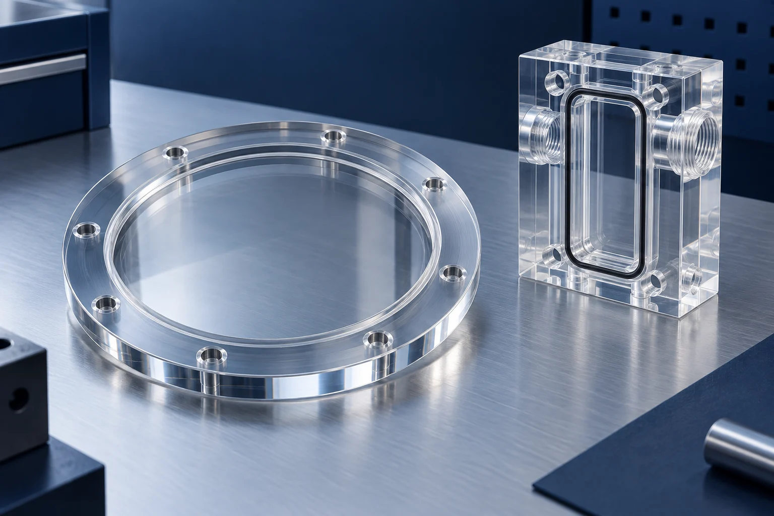
Surface finishing for custom CNC plastic parts: from acrylic edges and transparent windows to housings, manifolds and optical component requirements. We review the material, finish zones and critical geometry together.
Texture. Appearance. Clarity.
01
Plan the finished surface together with the material, geometry and inspection criteria. The quoted route depends on the part, rather than a universal polishing recipe.
| Project consideration | Scope for review |
|---|---|
| Primary service | Surface finishing for custom CNC machined and fabricated plastic components. |
| Main materials | Acrylic / PMMA and polycarbonate; other polymers require compatibility review. |
| Finishing routes | Mechanical polishing, edge finishing and precision CNC finishing. Diamond, flame and vapor methods require project-specific availability and compatibility confirmation. |
| Surface objectives | Functional texture, cosmetic appearance, transparent viewing or specified optical performance. |
| Typical components | Inspection windows, covers, housings, observation blocks, manifolds and light guides. |
| Production | Prototypes, small batches and repeat OEM orders. |
| Acceptance | Final dimensions and visual criteria agreed before manufacture; instrumented finish or optical checks require an agreed inspection method. |
| Quotation inputs | Material grade, starting surface, designated finish areas, quantity, tolerances and application. |
02
Plastic polishing improves surface smoothness, appearance or transparency after machining, cutting or fabrication. A suitable method depends on the polymer, starting condition, accessible geometry and target finish.
Surface smoothing reduces fine texture. Cosmetic finishing controls visible scratches, gloss and tooling marks. Optical finishing addresses the actual viewing or light-handling function, with acceptance criteria beyond gloss alone. These objectives can overlap, but they should be specified separately on the drawing.
A clear-looking surface is not automatically an optical component. Deep damage may need preparation or corrective machining before finishing, and inaccessible channels may retain their machined texture. Review the final dimensions, stress sensitivity and cleaning conditions as part of the process selection. Polishing should improve the surfaces that matter without compromising the features that make the component work.
03
Match the process to the surface. The methods below describe available finishing approaches for assessment; specialist routes are confirmed in the quotation before any commitment.
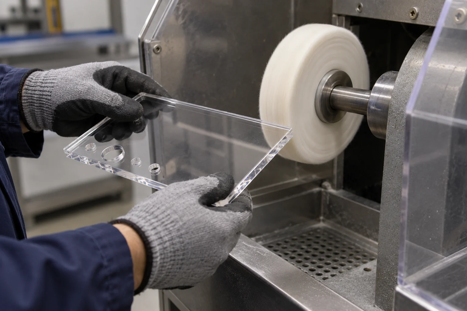
Controlled abrasives and compounds refine prepared accessible surfaces and edges. Suitable PMMA covers, windows and housings may benefit. Manage pressure, heat and contamination; deep marks need preparation first.
Precision cutting tools can produce smooth, clear edges on suitable acrylic sheet. Straight, accessible edges are the main use case. Confirm equipment availability, geometry and the edge acceptance standard.
Controlled surface heating can improve suitable PMMA edges, but can introduce stress or rounding. Review subsequent bonding and service exposure. This is a material-specific route requiring confirmation, not a general treatment for every clear plastic.
A specialized enclosed, controlled process using a compatible finishing medium. Certain specified polymers, including some polycarbonate applications, may be candidates. Material, stress, handling and qualified process availability must be established; no general in-house vapor capability is implied.
A suitable cutter, toolpath and finishing pass can provide the functional surface while maintaining geometry. This may be preferable on bores, mating surfaces, opaque engineering polymers or features that cannot tolerate secondary material removal.
Polishing alone cannot reliably remove every deep scratch, chipped edge or heavy tool mark. Correct the starting surface before selecting the final treatment.
04
Acrylic and polycarbonate are the primary transparent materials to review, but their finishing risks differ. Formulation, coatings, stock history and residual stress can change compatibility.
Define viewing faces, exposed edges and surfaces that will later be bonded.
Acrylic / PMMA →Define optical or cosmetic needs and disclose cleaning chemicals, coatings and mechanical loads.
Polycarbonate →| Material | Main objective | Process consideration |
|---|---|---|
| Acrylic / PMMA | Clarity and glossy accessible edges | A strong candidate for mechanical and appropriate edge finishing; protect bond interfaces. |
| Polycarbonate / PC | Improved clarity and appearance | Review solvent-related stress cracking, coatings and residual stress; do not copy an acrylic process without assessment. |
| PETG | Cosmetic clarity | Grade and finishing method dependent. |
| ABS | Cosmetic surface condition | Usually an appearance objective rather than transparency. |
| Ultem / PEI | Improved machined surface | Specialized process and grade review required. |
| PEEK | Functional finish | Precision machining is generally more relevant than optical polishing. |
| POM / Delrin | Smooth functional surface | Fine CNC machining is generally preferred. |
| PTFE / UHMW | Functional finishing | Conventional polishing may provide limited benefit; prioritize geometry and service requirements. |
05
Surface roughness describes small-scale texture, often expressed as Ra or Rz. Optical clarity also depends on transmission, haze, scattering, distortion, surface shape and the material itself. Low roughness does not automatically establish optical suitability.
| Required function | Acceptance criteria to define |
|---|---|
| Smooth functional surface | Surface roughness and final dimensions. |
| Cosmetic finish | Visible scratches, gloss and tooling marks under agreed lighting. |
| Clear viewing window | Transparency, haze and visual distortion. |
| Light guide | Optical performance, surface geometry and specified light path. |
| Fluidic observation component | Visibility, channel condition and cleanliness. |
| Precision mating surface | Dimensions, flatness and finish. |
Specify the function rather than only asking for a “mirror finish.” For optical acceptance, agree the test, equipment or qualified inspection partner before quotation. No universal clarity percentage or roughness value applies to every part.
06
Polishing can remove or redistribute surface material, round edges and change final geometry. Identify tight-tolerance surfaces before choosing the finishing route.
| Feature | Potential impact |
|---|---|
| Precision bore | Diameter or fit changes. |
| Flat sealing surface | Local flatness or texture changes. |
| Acrylic edge | Rounding and loss of a sharp reference edge. |
| Thin wall | Heat or pressure distortion. |
| Optical window | Surface shape changes and visual distortion. |
| Threaded feature | Loss of dimensional definition. |
| Small channel | Surface changes or incomplete access. |
Mark no-polish areas, datums, sealing lands and inspection state on the drawing. Define whether a dimension applies before or after finishing; final acceptance should reflect the delivered component.
Request a Surface Finish & Tolerance Review →07
The starting material and process history matter as much as the final polishing step. Acrylic and polycarbonate need different compatibility assessments.
Stock condition, machining and clamping can introduce or release internal stress. Evaluate stress-sensitive parts and any material-specific conditioning requirement before finishing.
Uncontrolled heat can distort the part, damage the surface or introduce additional stress. Thin sections and sharp transitions need particular care.
Incompatible media can cause crazing or environmental stress cracking. Confirm the polymer grade, exposure and residual stress rather than relying on a generic plastic label.
Deep scratches, chips and damaged machined surfaces may require sanding or corrective machining. A glossy finish cannot conceal every underlying defect.
Successful finishing can be spoiled by abrasive wiping, debris or unprotected stacking. Agree compatible cleaning and non-abrasive protection.
08
Surface appearance examples: these matched visual comparisons illustrate a machined surface and a possible finished appearance. They are not measured TOPS production results; actual acceptance must be established on project samples.
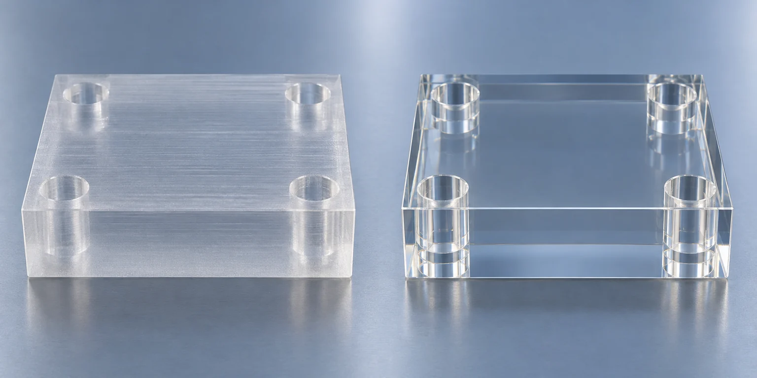
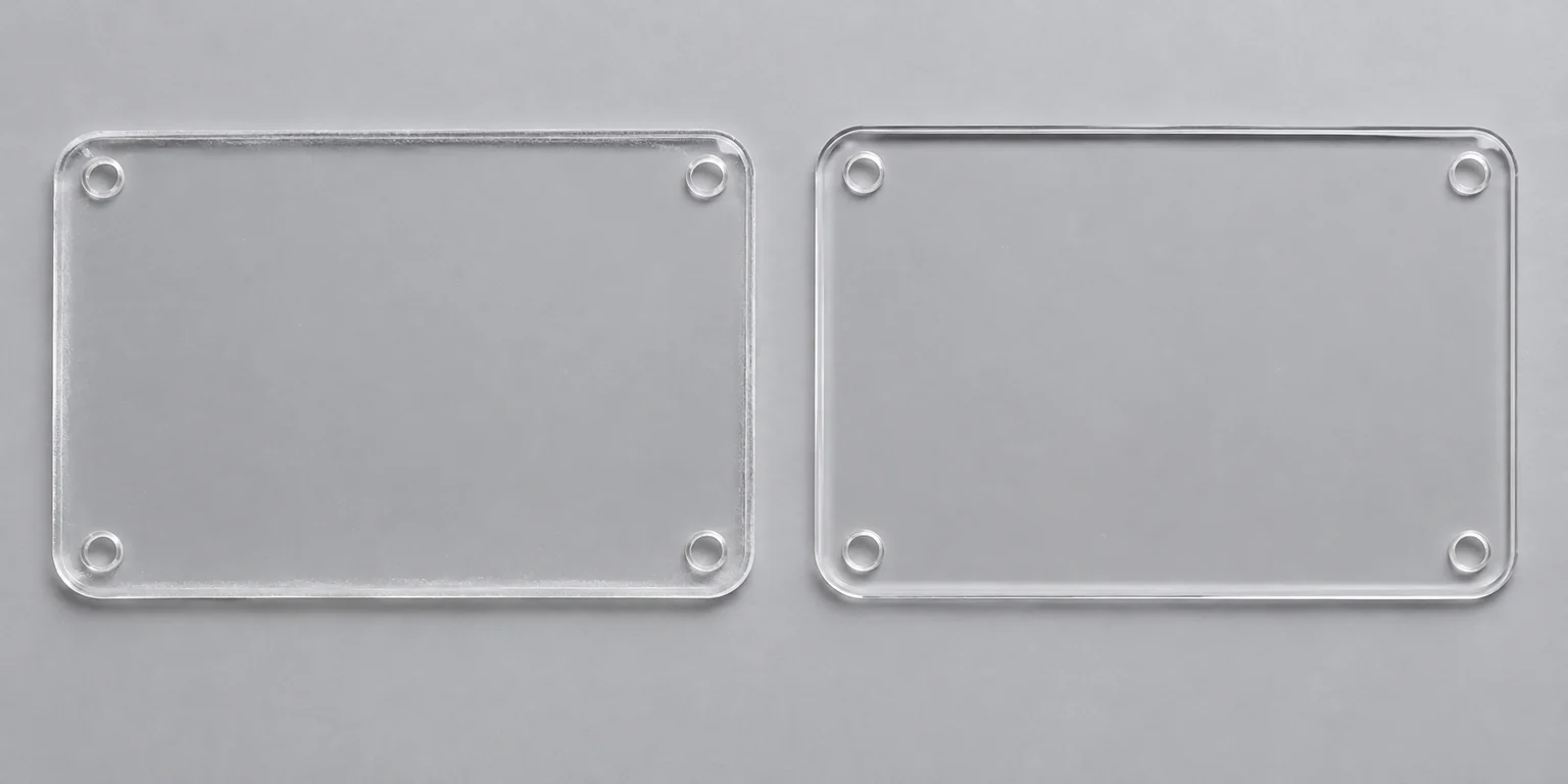
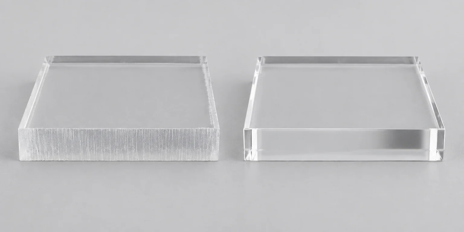
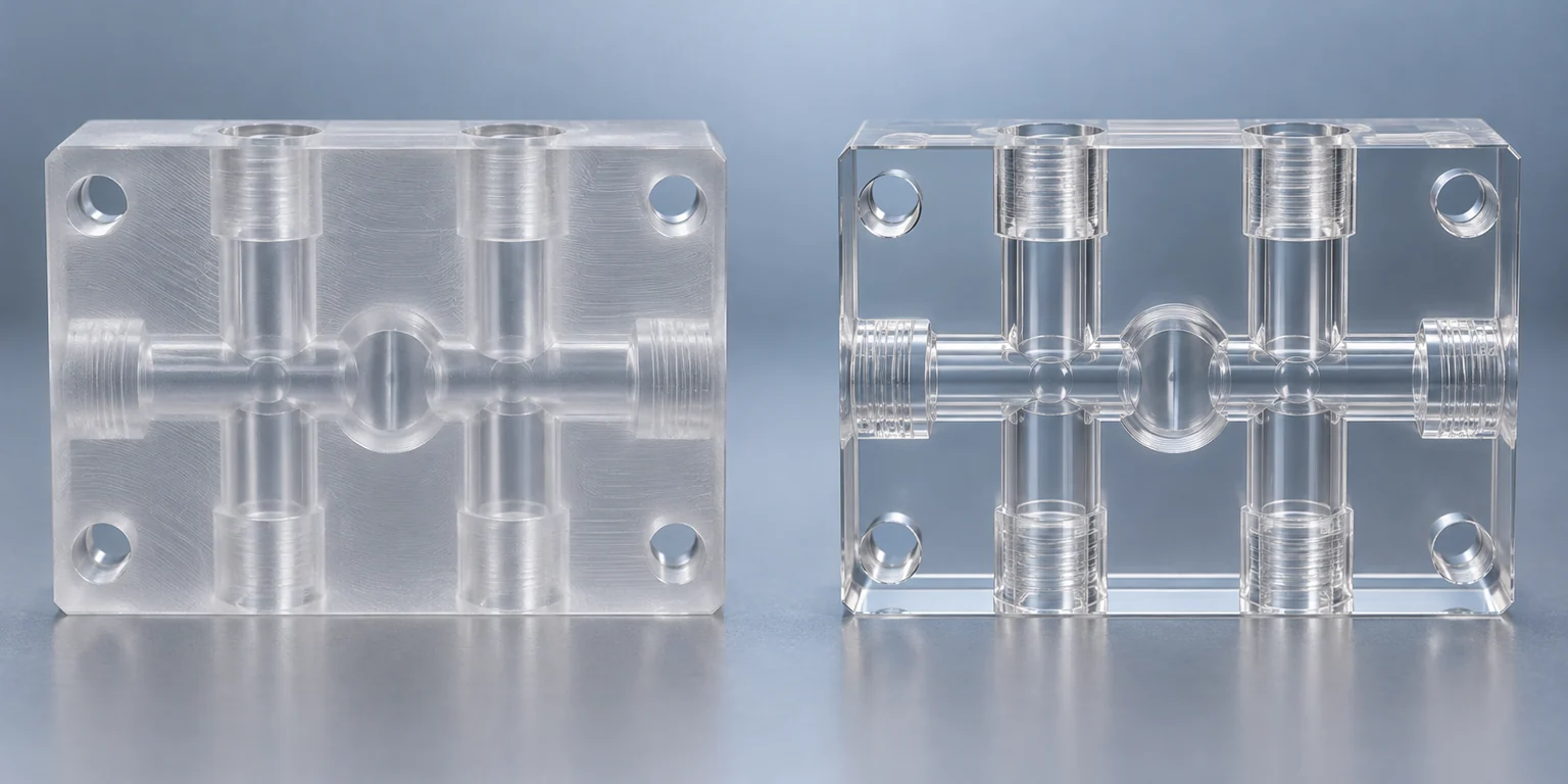
Compare the same geometry under consistent lighting. Evaluate designated viewing faces and edges separately from internal bores. A more transparent external face does not prove dimensional compliance or finished internal channels.
09
Planning machining and polishing together helps coordinate dimensional features with cosmetic or optical surfaces. It can reduce avoidable rework, protect critical geometry and simplify sourcing.
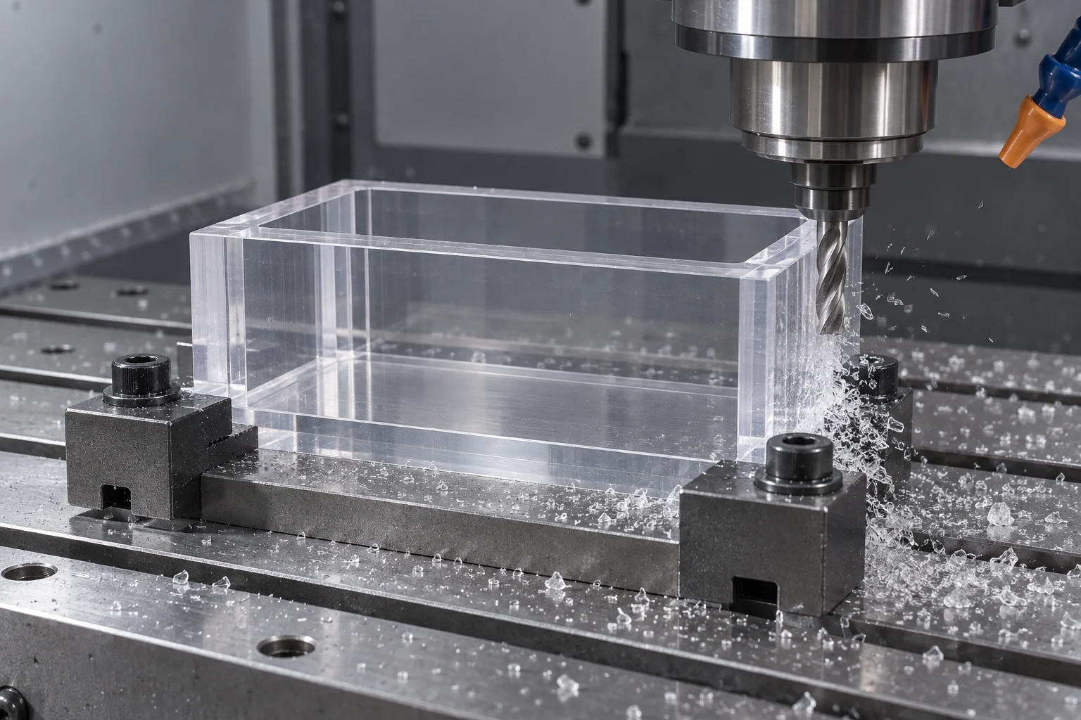
CAD & surface review — identify finish zones and acceptance criteria.
Material selection — confirm grade, coating and compatibility.
CNC milling / turning — establish geometry and a suitable starting surface.
Deburring & preparation — remove defects without damaging datums.
Polishing / finish machining — apply the agreed route to designated areas.
Dimensional & visual inspection — verify the delivered condition.
Protective packaging — preserve the accepted surface through shipment.
10
Industrial components need a finish that serves their application. These component concepts show common requirements; the material and acceptance plan remain project specific.
Transparency, clean exposed edges and stable mounting features.
Viewing quality with controlled surface condition and material compatibility.
External visibility, fluid passage observation and specified channel cleanliness.
Defined optical surfaces and geometry appropriate to the light path.
Consistent cosmetic finish while preserving fits and interfaces.
Visibility into the component and a suitable cleaning plan.
Consistent appearance on viewing areas and accessible edges.
Functional texture and final dimensional acceptance.
11
A drawing with marked finish zones is more useful than a blanket instruction to polish the entire part.
Mark optical faces, viewing areas and cosmetic zones separately. Identify hidden faces and areas that must remain as machined.
Specify Ra/Rz where relevant, or agree a visual reference, lighting, viewing distance and acceptable defects. Define optical criteria separately.
Consider material removal, edge rounding and the final inspection state. Protect sealing lands, bores, threads and datums.
Fragile walls and unsupported projections may distort under pressure or heat. Provide accessible, supportable geometry where possible.
Disclose cleaners, adhesives, fluids and service temperatures so the finishing method can be reviewed for compatibility.
Bond interfaces may need a controlled machined finish. Polishing can round edges, while heat-induced stress can increase crazing risk during solvent bonding.
12
Plastic polishing primarily improves surface condition. CNC finish machining primarily controls geometry and dimensions. Some components benefit from both.
| Factor | Plastic polishing | CNC finish machining |
|---|---|---|
| Primary objective | Surface appearance or texture | Geometry and dimensional accuracy |
| Main methods | Buffing, abrasion or confirmed specialist routes | Controlled precision cutter passes |
| Optical clarity | Possible with a suitable material and process | Additional finishing may be needed |
| Critical bores | Requires careful control of material removal | Usually preferred for dimensional control |
| Clear acrylic edges | A useful application for appropriate edge finishing | May require follow-up polishing |
| Tight geometric tolerance | Secondary finishing can affect geometry | A more directly controlled machining objective |
13
Agree both visual and dimensional acceptance before manufacturing. Instrumented roughness, haze or optical testing must be specified and confirmed with appropriate equipment or a qualified partner.
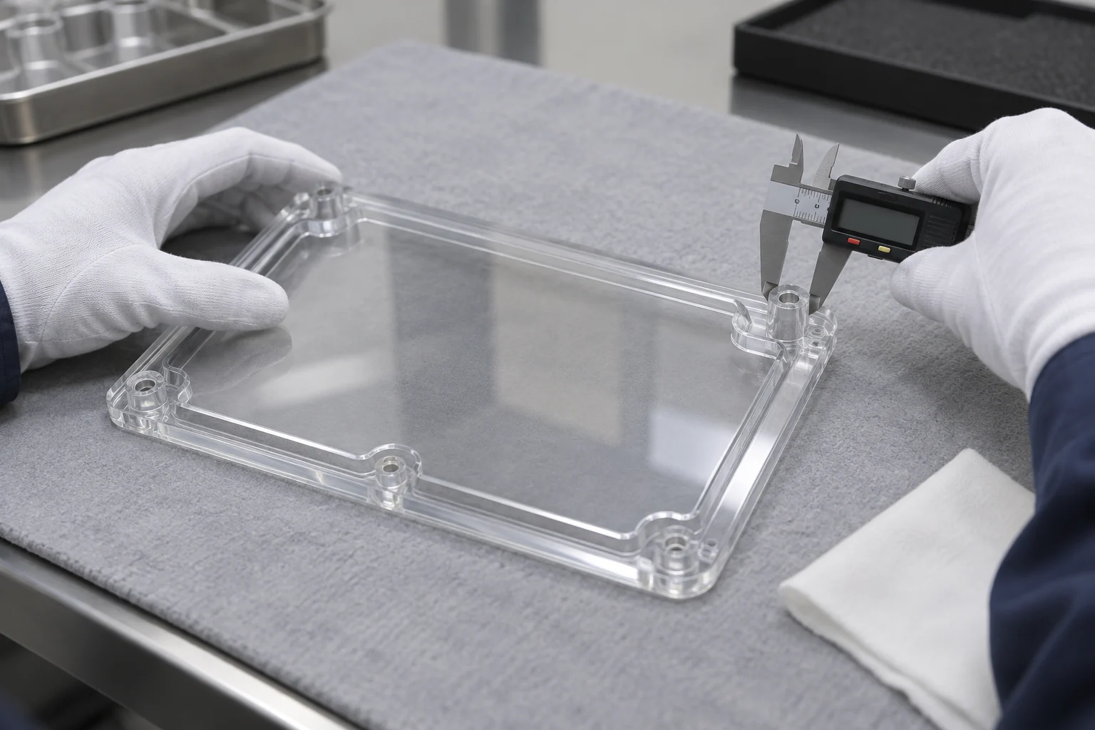
Check scratches and haze against an agreed reference.
Inspect visible tooling marks on designated faces.
Review exposed edge clarity and condition.
Check polishing uniformity under agreed lighting.
Verify final dimensions and specified flatness.
Measure surface roughness where agreed.
Verify optical criteria using the confirmed inspection plan.
Check for stress cracking and crazing.
Confirm cleanliness and protective packaging.
14
Select the finished surface around its actual role in the equipment. Suitability for a regulated or optical application requires the project-specific qualification plan.
Transparent housings and inspection windows; define cleaning and documentation requirements.
Viewing blocks and light guides with application-specific optical criteria.
Selected inspection covers and optical components with specified cleanliness.
Transparent guards and panels with controlled finish zones.
Sensor windows and protective covers with defined viewing areas.
Display windows and instrument components with cosmetic or optical acceptance.
15
Start with a review of the material, drawing and finished-part requirements, then agree a practical manufacturing and acceptance route.
Assess polymer compatibility, starting surface and exposure before choosing a method.
Plan cosmetic needs and dimensional features together rather than treating finishing as an afterthought.
Identify the surfaces that need additional treatment and those best left precision machined.
Use qualification samples to establish an agreed reference for subsequent orders.
Inspect the delivered component against defined geometry and appearance requirements.
16
A clear sequence connects your drawing to the final protected component. Confirm specialist processes and inspection scope during the quotation stage.
Receive CAD files, drawings and surface requirements.
Confirm the plastic material and exact grade.
Identify functional, cosmetic and optical surfaces.
Evaluate the starting machined surface condition.
Select and confirm a suitable finishing method.
Carry out agreed preparation and finishing.
Inspect appearance and critical final dimensions.
Clean, protect and package finished components.
17
Plastic polishing refines a prepared plastic surface after machining, cutting or fabrication to improve texture, appearance or transparency. The route may involve controlled mechanical finishing, an appropriate edge process or precision finish machining. Material compatibility and the required final geometry determine the choice. Cosmetic gloss and optical performance are different requirements and should have separate acceptance criteria.
Acrylic / PMMA and polycarbonate are common transparent candidates, but they require different process assessments. PETG, ABS and some other grades may also benefit from a suitable finishing route. PEEK, POM, PTFE and UHMW generally call for functional finish control rather than optical polishing. Confirm the grade, coating, stress condition and service exposure before selecting any chemical or thermal treatment.
Suitable acrylic surfaces can often be made clearer after machining when the starting condition, geometry and preparation allow it. Deep marks or damage may need corrective machining or sanding first. Specify which faces must be transparent and how they will be accepted. A clear external face does not establish optical-grade performance or guarantee that internal passages receive the same finish.
Acrylic is a common candidate for mechanical and appropriate edge finishing. Polycarbonate requires its own compatibility assessment, particularly for solvents, coatings and residual stress. An acrylic flame or solvent process should not be transferred to polycarbonate without qualification. Both materials need controlled handling, defined finish zones and a final inspection plan based on the actual application.
Vapor polishing is a specialist process in which a compatible finishing medium acts on accessible polymer surfaces in controlled equipment. Some specified polymers and geometries may be candidates. It is not universally compatible and does not remove the need to assess stress, geometry and final dimensions. TOPS confirms qualified process availability and the inspection scope before including this route in a quotation.
Polishing can reduce suitable fine machining marks after adequate preparation, but it cannot reliably remove every deep groove, scratch or damaged edge. Corrective machining or staged surface preparation may be needed. Inaccessible features may not respond like an exposed face. Review the starting condition and the allowable material removal before deciding whether secondary polishing or a better CNC finishing pass is appropriate.
Yes. Material removal, redistribution, heat or pressure can change dimensions, round edges or affect flatness. Mark critical bores, threads, sealing lands and datums, and identify areas that must remain as machined. Agree the final inspection state and the acceptable edge condition. A precision CNC finish may be preferable where the feature cannot tolerate secondary finishing effects.
Yes. Residual stress, incompatible chemicals and subsequent exposure can contribute to crazing or environmental stress cracking. A glossy appearance does not establish a stress-free part. Review the stock condition, machining history, finishing method, cleaning agents and service loads together. Material-specific conditioning may be appropriate, but it must be assessed for the actual grade and component rather than assumed universally.
Mechanical polishing uses controlled abrasive action and compounds to refine a prepared surface. Flame polishing uses localized heat on compatible acrylic edges and can introduce stress or rounding. The two methods have different access, geometry and downstream bonding implications. Confirm the material and process availability first; a heat-finished edge should not automatically be treated as suitable for solvent bonding.
Send the drawing and finishing requirements for a combined review. TOPS can plan the machining geometry, surface preparation and suitable finishing route together, with specialist methods and inspection arrangements confirmed in the quotation. Identify the finish zones, material grade and final tolerances so the proposal covers the delivered component rather than only its machined starting condition.
YOUR SURFACE. YOUR SPECIFICATION.
Send your CAD model, engineering drawing and photos of the existing surface. Specify the material grade, quantity, required finish, optical or cosmetic areas, critical tolerances and application. We can review whether mechanical polishing, CNC finishing or another confirmed route fits your requirements.
Keep the form simple: country, part number and quantity are optional. Include the detailed finish requirements and reference photos in your drawing package or ZIP, or share them by email. Company, name, email and phone are required; drawing upload is optional.
info@tops-precision.comSTEP / STP / IGES / X_T / DWG / DXF / PDF or ZIP, maximum 10 MB. Larger drawing packages can be shared by email. Agree confidential-file handling before sending sensitive drawings.