01
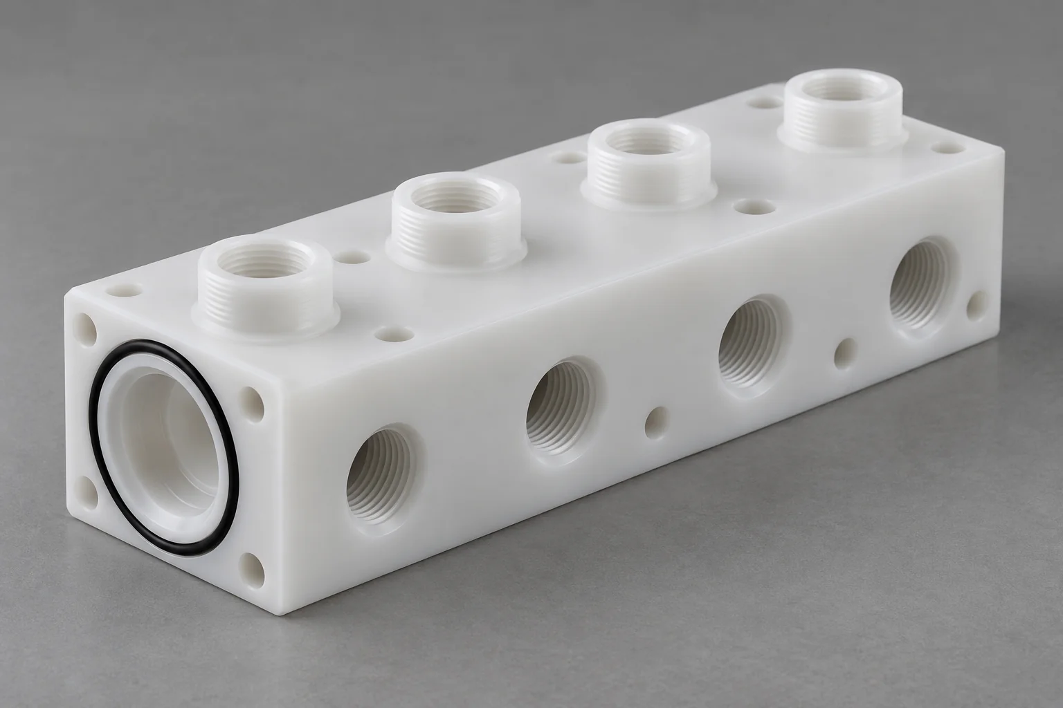
Plastic Manifolds
Fluid-routing blocks for chemical, gas, pneumatic or vacuum systems. Define port standards, internal passage intersections, sealing features and the actual media.
Explore component details →
ENGINEERING PLASTICS · SEMICONDUCTOR EQUIPMENT
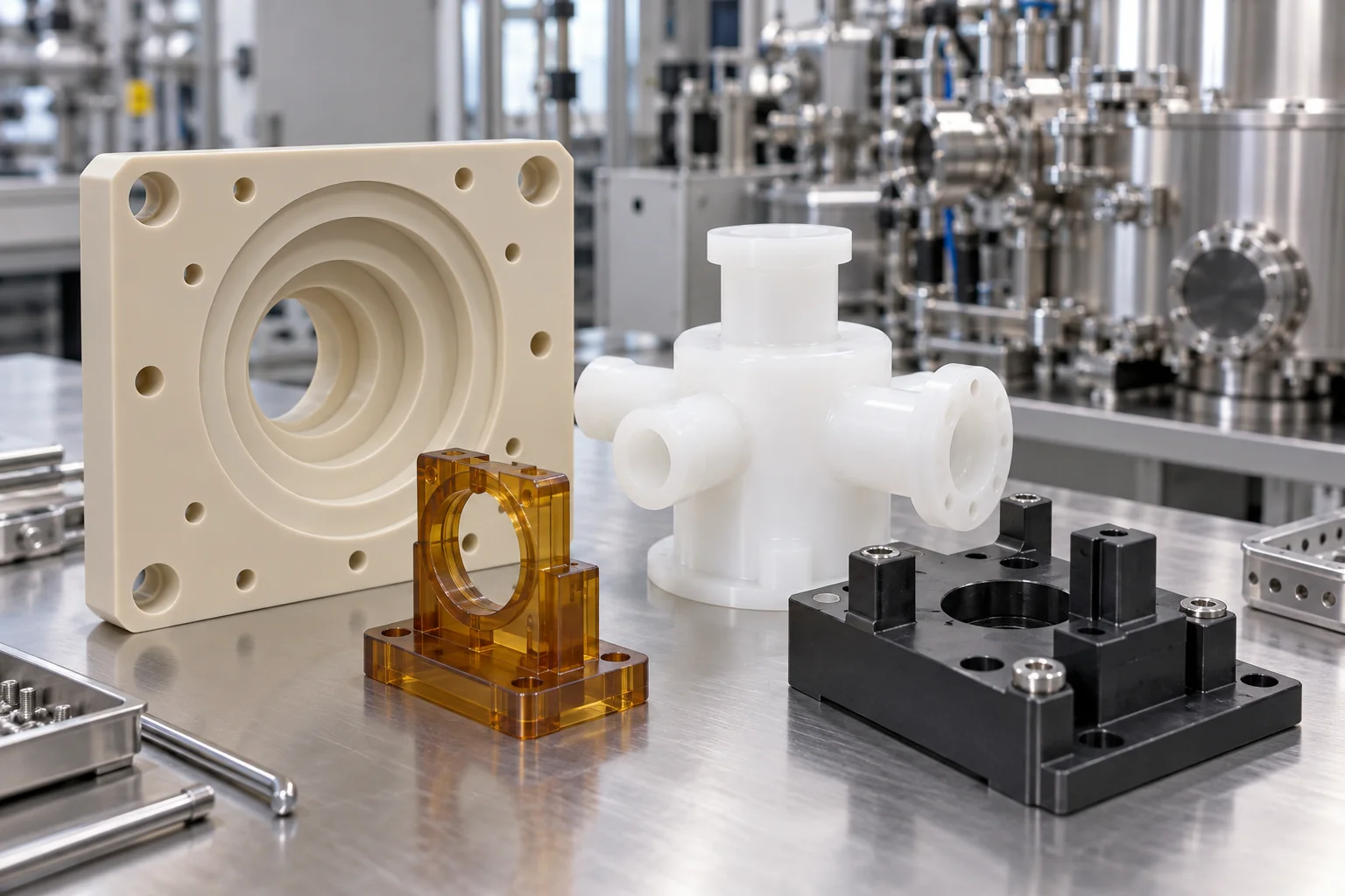
TOPS Plastics manufactures custom CNC machined plastic components for semiconductor manufacturing equipment, wet-process systems, wafer handling, chemical delivery, electrical isolation, automation and analytical systems. We machine PEEK, PVDF, PTFE, PPS, PEI, PAI and other engineering polymers according to customer drawings, material specifications, tolerance requirements and application conditions.
From a ported fluid block to an insulating support, the machining route follows the functional geometry and operating specification.
| Capability | TOPS Plastics |
|---|---|
| Typical parts | Manifolds, insulators, fixtures, housings, spacers and guides |
| Materials | PEEK, PVDF, PTFE, PPS, PEI, PAI / Torlon and specified grades |
| Processes | CNC milling, turning, 5-axis machining, drilling and tapping |
| Key requirements | Chemical resistance, dimensional stability and electrical insulation |
| Production | Prototype, low-volume and repeat OEM production |
| Drawing input | STEP / CAD models, PDF drawings and reference samples |
| Inspection | Drawing-based dimensional inspection of agreed features |
| Documentation | Material and inspection documentation where specified, agreed and available |
Connect the component function to its process environment. Explore drawing-based parts, then define material, interfaces and acceptance requirements.
Fluid-routing blocks for chemical, gas, pneumatic or vacuum systems. Define port standards, internal passage intersections, sealing features and the actual media.
Explore component details →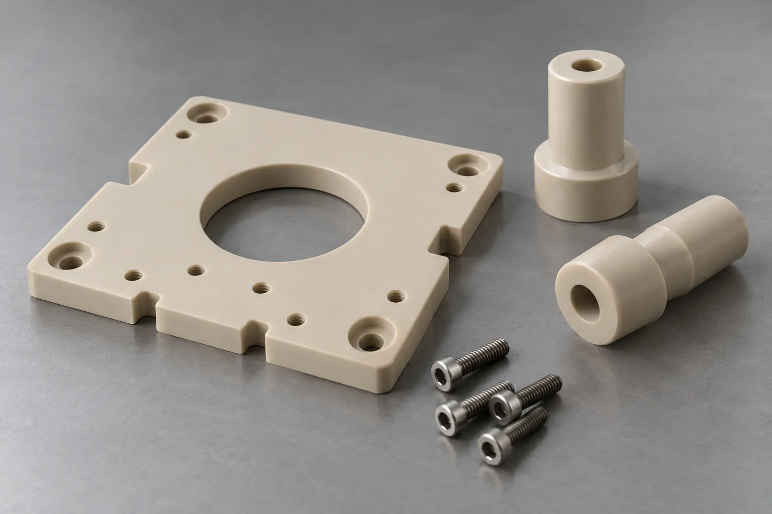
Electrical isolation, controlled spacing and structural support. Specify the exact material grade and required dielectric, thermal and flame-related criteria.
Explore component details →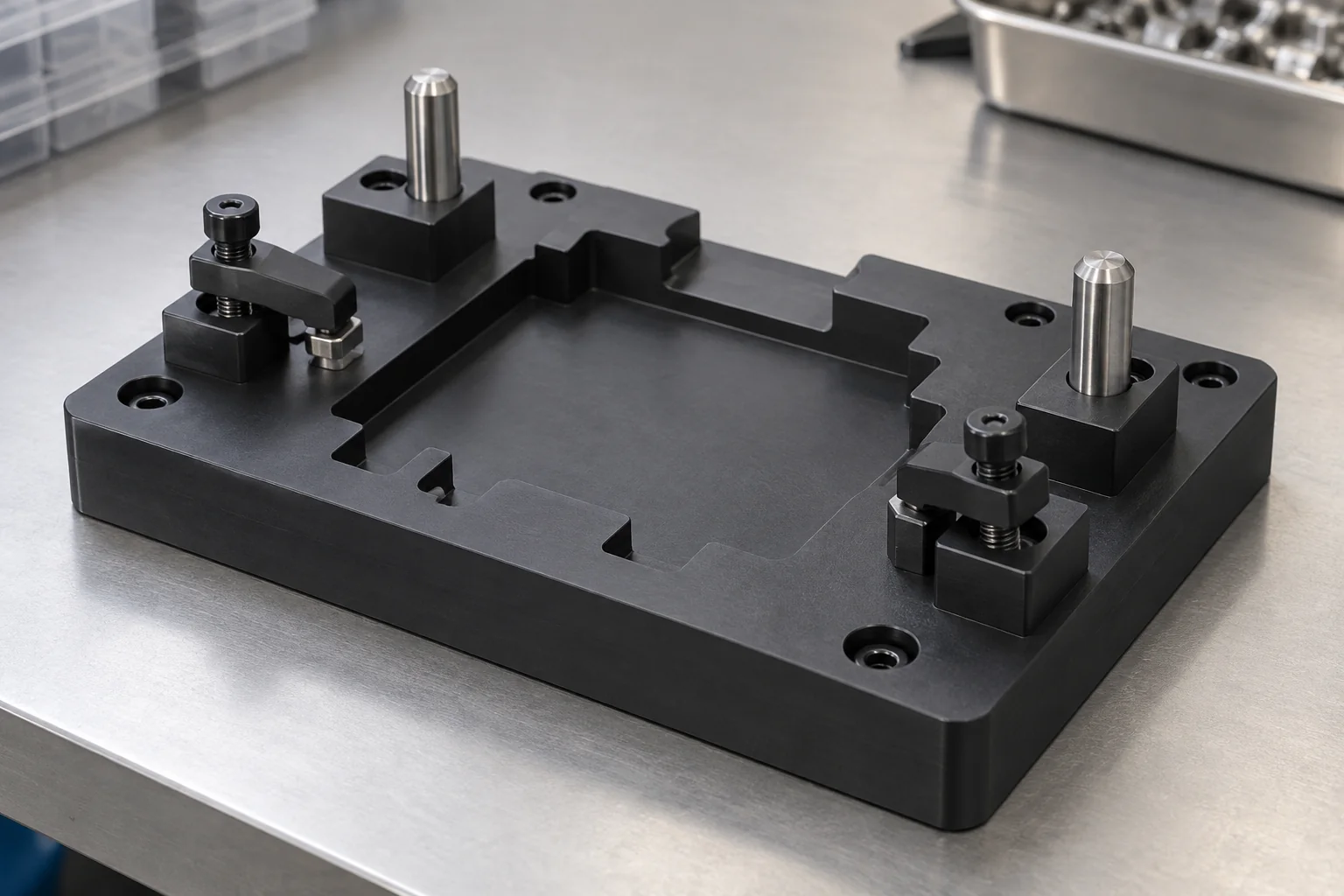
Equipment assembly, positioning, testing, inspection and selected handling functions. Define datums, contact areas, cycle count and electrical requirements.
Explore component details →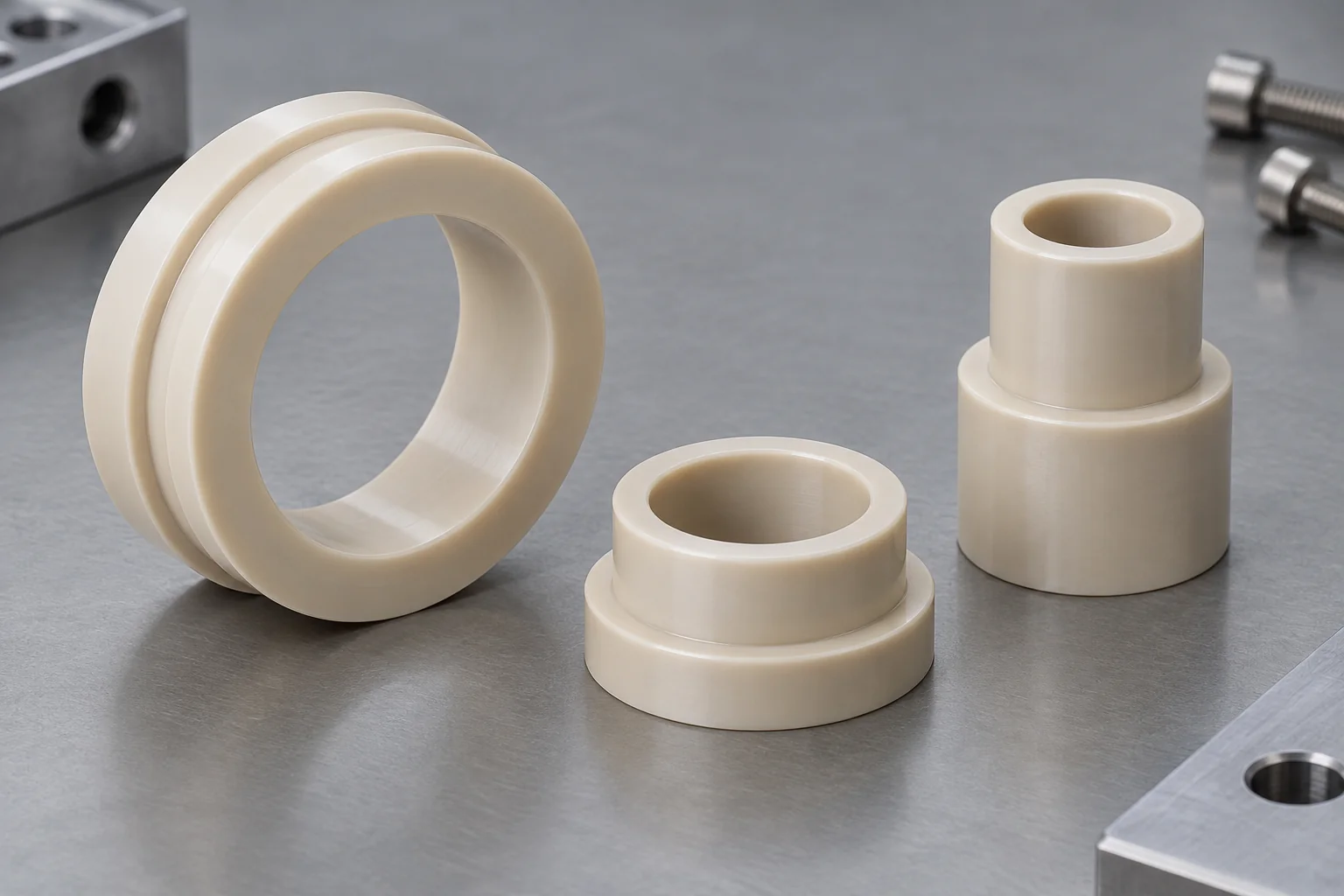
Control stack height and separate electrical or mechanical interfaces. Identify thickness, parallelism, mounting load and the measurement temperature.
Explore component details →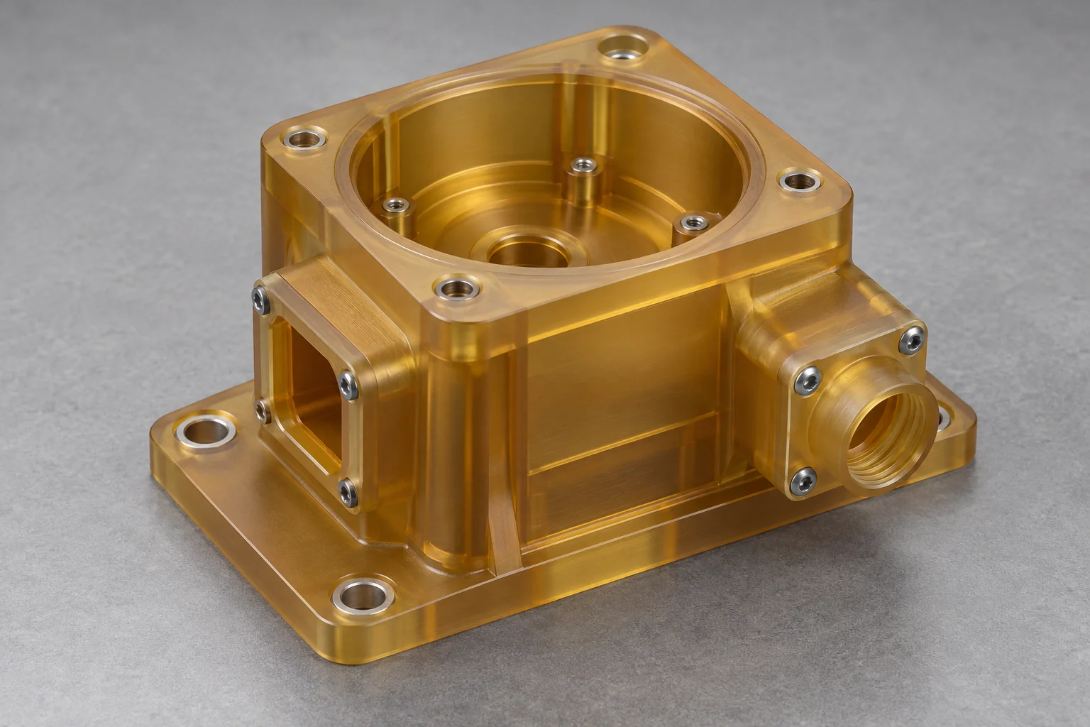
Sensor, electronics and precision-equipment bodies with cavities, mounting patterns and connector openings. Review access, stiffness and environment.
Explore component details →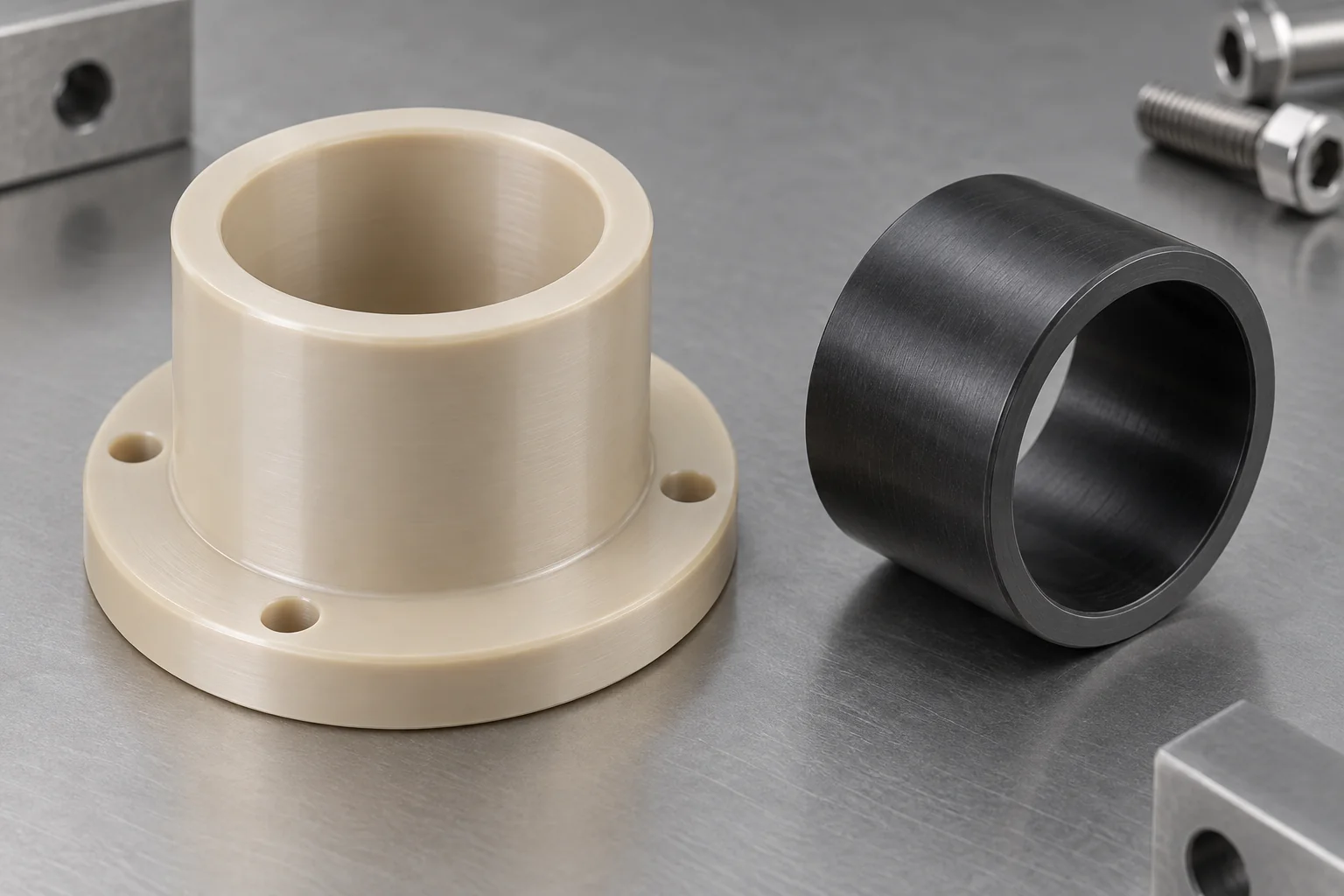
Low-friction guidance and motion components. Review wear, mating surfaces, clearance, thermal movement and particle sensitivity.
Explore component details →Plastic Bushings →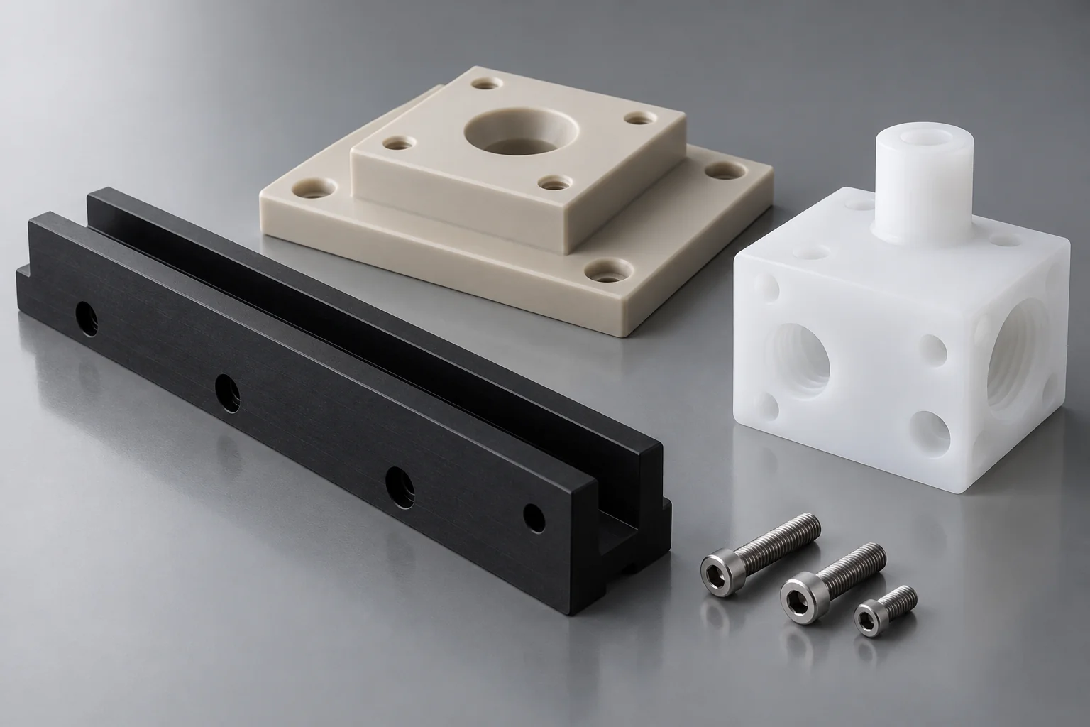
Nonstandard plates, blocks, guides and interfaces manufactured to released CAD and drawing requirements, with a process-specific material review.
Explore component details →Start with the process zone. A polymer that works in a structural support may be unsuitable in a wetted flow path or close to a wafer.
Chemical manifolds, valve blocks, tank parts, supports, spray components and fixtures. Review chemistry, cleanliness and dimensional stability together.
Guides, supports, positioning fixtures, grippers, spacers and low-friction parts. Contact geometry, particle generation, surface protection and repeatability matter.
PVDF manifolds, PTFE components, valve bodies, routing blocks and fitting interfaces. Specify concentration, pressure, temperature and exposure duration.
Insulators, support parts, housings and structural interfaces. Review vacuum level, temperature, conditioning and required outgassing evidence.
Insulators, connector housings, sensor bodies and terminal supports. Electrical ratings and ESD requirements must refer to a documented grade and assembly.
Jigs, nests, checking fixtures and precision locators. Establish functional datums, repeatability criteria and a suitable measurement state.
There is no single best plastic. Compare the exact resin grade against chemistry, temperature, load, electrical behavior, contamination sensitivity and dimensional needs.
| Material | Main advantage | Application direction | Review before selection |
|---|---|---|---|
| PEEK | Mechanical, thermal and chemical performance | Structural precision parts, insulators and fixtures | Fillers, temperature, chemistry and required purity evidence |
| PVDF | Chemical resistance and useful stiffness | Wet-process manifolds and fluid parts | Exact chemical, concentration, temperature and grade documentation |
| PTFE | Broad chemical resistance and low friction | Chemical-handling and isolation components | Creep, stiffness, dimensional behavior and grade-specific compatibility |
| PPS | Dimensional and chemical performance | Precision technical components | Brittleness, fillers and contact requirements |
| PEI / Ultem | Electrical and thermal performance | Insulators and equipment supports | Solvent exposure and exact electrical ratings |
| PAI / Torlon | Strength, wear and dimensional performance | Loaded precision components | Conditioning, moisture, temperature and cost |
PEEK is often considered for loaded or higher-temperature structures, PVDF for compatible fluid paths, and PTFE for chemically demanding low-friction interfaces. PPS, PEI and PAI serve different dimensional, electrical, thermal and wear needs. Material-family names do not establish process qualification.
Wet-process equipment may expose components to acids, bases, solvents, ultrapure water and cleaning mixtures. Selection begins with the exact media, concentration, temperature, exposure duration and cleanliness requirement.

Manifolds, distribution blocks, fittings and valve interfaces require a defined passage layout, port standard and accessible inspection strategy.
Tank components, valve supports and fixtures need chemical compatibility as well as adequate stiffness under operating load.
Spray blocks and routing details need burr control at intersections and drawing-based orifice geometry. Define any required flow or leak testing separately.
PVDF, PTFE, PEEK and PPS may be candidates depending on the actual chemistry and grade. Review mixtures and cleaning cycles, rather than selecting by an acid / base label.
A chemically resistant polymer is not automatically suitable for a high-purity fluid system. Discuss extractables, trace contaminants, surface condition and documentation limits where these affect your process. Provide seal and fitting specifications with the component drawing.
Wafer-handling parts need more than low friction. Evaluate material stability, wear, particle generation, dimensional repeatability and the actual wafer-contact interface together.
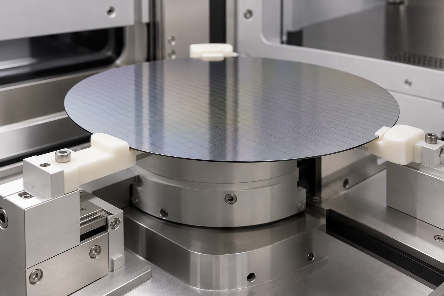
Define permitted edge or support contact zones, radii, surface finish and handling clearance. Avoid unintended rubbing against sensitive surfaces.
Guides, rollers, bushings, spacers and grippers require load, speed, cycle count and mating-material review. Wear debris can be as important as wear life.
Nests and fixtures need functional datums, appropriate clearances and thermal stability. Confirm the part position under the intended operating load.
Specify documented electrical properties where needed and the actual thermal exposure. Ordinary insulating polymers are not automatically ESD-safe.
Wafer suitability and particle performance require application-specific validation. Specify the allowable contamination level and test method; a smooth machined surface or familiar polymer name alone is insufficient evidence.
Insulators, standoffs, spacers, connector parts, sensor supports and equipment blocks combine electrical and mechanical duties.
Consider for structural insulation under elevated temperature, subject to the exact grade, loads and service environment.
Consider where electrical and thermal performance are central; review solvent exposure and the required electrical rating.
Consider for stable, chemically compatible technical parts, with attention to fillers and notch-sensitive features.
Consider for loaded, wear-sensitive precision components; review conditioning and moisture effects before assigning tolerances.
Tie dielectric strength, electrical resistance and flame behavior to the actual grade and applicable test conditions. An insulating polymer and a static-dissipative grade perform different functions. Metal inserts, fasteners and the complete assembly also affect electrical isolation.
Potential parts include insulators, support blocks, sensor housings, valve components, spacers, fixtures and vacuum-system interfaces. Suitability depends on the system specification.
Provide operating pressure, temperature, bake conditions and duty cycle. These determine which material data are relevant.
Review the exact grade and formulation. Fillers, absorbed moisture and processing history can affect behavior.
Define cleaning, drying or conditioning requirements and any chemical exposure before installation.
Specify the required method and acceptance limit. Supplier data must match the grade and conditions; component qualification may still be needed.
Do not select a plastic for vacuum use solely by polymer name. The resin grade, fillers, conditioning, service temperature and customer outgassing specification must be reviewed before a vacuum-related commitment is made.
Components may operate near wafers, chemicals, gases or sensitive process equipment. Particles, chips, residues, incompatible lubricants and packaging can affect the intended process.
Specify resin, exact grade, fillers and documentation requirements. Keep approved substitutions subject to customer review.
Remove accessible burrs and chips from holes, passages, slots and surfaces. Define inspection access for hidden features.
Identify wetted surfaces and internal intersections. Agree cleaning requirements and any residue or particle acceptance method.
Define protective contact materials, bagging, labeling and shipment packaging during quotation. Packaging must suit the customer specification.
Provide the cleanliness level, handling procedure and acceptance criteria. Send the specification so feasibility can be confirmed.
Customer-specified cleanliness, handling and packaging requirements can be reviewed during quotation. The required cleaning process, verification method and documentation must be agreed before manufacture; a general machining quotation does not establish a cleanroom or purity qualification.
Dimensional accuracy must be maintained in materials sensitive to machining heat, clamping force, stock stress and environmental conditions.
Polymers generally move more with temperature than metals. Define service and inspection temperatures for fit-critical features.
Heavy stock removal can release residual stress. Consider geometry, stock condition and a machining sequence suited to the material.
Clamping and measurement forces can distort flexible walls. Design adequate support and agree the measurement state.
Long tool reach and restricted chip removal affect heat, finish and access. Review pocket depth and internal radii early.
Manifold ports, fixture locators and equipment mounting patterns need a clear datum relationship and inspection plan.
PTFE, PVDF, PEEK and PAI respond differently to cutting, support and temperature. A machining approach must suit the selected grade.
Material stability, contamination control, burr removal, functional feature relationships, surface protection and correct documentation often matter more than assigning tight tolerances everywhere. Review the features that control sealing, alignment and handling first.
Evaluate compatibility using the exact polymer grade, chemical identity, concentration, temperature and exposure duration. Do not reduce selection to a simple acid-equals-PTFE rule.
Provide the exact substance or mixture, including cleaning agents and process changes. A trade name may require a composition specification.
Dilute and concentrated solutions can behave differently. State the operating range and any transient conditions.
Compatibility and mechanical performance can change with temperature. Include continuous, peak and cleaning temperatures.
Distinguish splash, intermittent contact, continuous immersion and repeated cleaning cycles.
Chemical resistance alone does not demonstrate retained stiffness, sealing performance or resistance to stress-related damage.
Define relevant extractables, ionic contamination, particles or other process acceptance criteria and required evidence.
Use current supplier data for the exact material and chemistry as a screening input. Where the service is critical, customer qualification or representative testing may be necessary. Specify seals and other wetted materials as part of the system review.
Burrs, chips, rough passage intersections and damaged contacts can interfere with assembly, flow, cleanliness and positioning.
Specify edge condition at intersecting passages and the inspection method for internal features. Avoid inaccessible burr traps where practical.
Define functional edges, port entrances and threaded interfaces. Check that deburring does not remove required geometry.
Identify sensitive contact zones, finish requirements and scratch acceptance. Protect these faces during handling and shipment.
Consider how a passage will be checked and cleaned before releasing a design. Agree flow, leak or internal-visual testing separately if required.
Identify the features that control sealing, positioning, fluid routing, handling or alignment. Agree realistic feature-specific tolerances after material and geometry review.
| Feature | Why it matters |
|---|---|
| Hole position | Equipment assembly and locating relationships |
| Flatness | Mounting or sealing contact |
| Parallelism | Fixture and equipment alignment |
| Bore diameter | Shaft, insert or mating-component fit |
| Port position | Fluid-system connection and routing |
| O-ring groove | Seal geometry and compression |
| Spacer thickness | Stack height and clearance |
| Datum relationship | Repeatable assembly and inspection |
| Surface condition | Contact, finish and cleanliness requirements |
No single tolerance applies to all semiconductor plastic parts. Grade, size, support, thermal movement, wall thickness and measurement force affect feasibility. Include GD&T, inspection temperature and the free or restrained measurement state where relevant.
Define the evidence needed with your RFQ. Availability, scope and acceptance criteria are confirmed for the specific order.
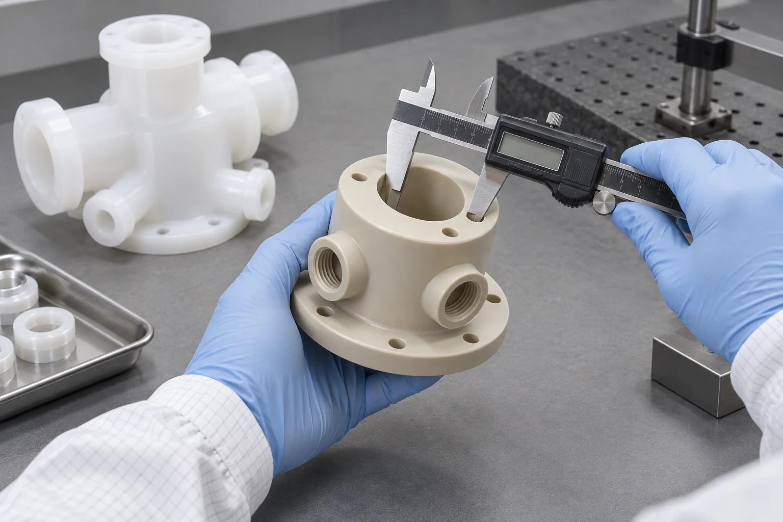
Inspect agreed critical dimensions and datum relationships against the released drawing. Define the measurement method for flexible or internal features.
Request certificates or supplier grade documentation where specified and available. Identify the exact evidence needed before material purchase.
State the required traceability depth, labeling and retention period so support can be confirmed during quotation.
Request a first-article scope and sample quantity where needed. Agree the report format and critical features in advance.
Define dimensional report requirements, sampling and additional tests. Flow, leak, particle or outgassing testing requires a separate agreed scope.
Use released CAD and drawing revisions, approved material grades and controlled changes for recurring programs.
Documentation supports a defined manufacturing and inspection scope. It does not by itself qualify a component for a semiconductor process. Provide customer standards and system validation requirements early so any feasibility limits can be resolved before production.
Equipment programs often need lower-volume, high-value components with controlled revisions rather than a generic mass-production route.
Check fit, material selection and intended function with representative components and operating conditions.
Refine critical tolerances, wall sections, contact interfaces and manufacturability using the agreed evaluation results.
Supply components for equipment builds, subsystem assemblies and pilot programs to the released specification.
Maintain the approved material grade, drawing revision, CNC program, inspection criteria and packaging requirements within the agreed order controls.
Review the process environment before production: chemistry, temperature, cleanliness, particle sensitivity, electrical behavior, vacuum exposure, dimensional stability and packaging all shape the component specification.
Review PEEK, PVDF, PTFE, PPS, PEI and other technical polymers against the actual operating requirements.
Machine multi-face components, ports, pockets, slots and precision interfaces to customer drawings.
Connect manifold, insulator, fixture, housing and custom-part requirements with an appropriate machining route.
Review tolerance priorities, wall thickness, support and material behavior before manufacture.
Support development components and recurring OEM equipment programs with released revisions.
Agree critical-feature checks, documentation and acceptance requirements for the order.
Move from application requirements to the detailed product page for geometry, interfaces and drawing preparation.
Direct answers about materials, wet-process parts, vacuum requirements, contamination and machining feasibility.
PEEK, PVDF, PTFE, PPS, PEI and PAI are common candidates for different equipment functions. Select the exact grade for chemistry, temperature, mechanical load, electrical behavior and cleanliness needs.
PEEK combines useful mechanical, thermal and chemical performance for structural parts, insulators and fixtures. Grade-specific purity, fillers and service conditions still require review.
PVDF may be considered where chemical compatibility and greater rigidity are needed; PTFE may suit other demanding chemical or low-friction interfaces. Compare exact grades, chemistry, temperature, creep and dimensional requirements rather than choosing by family name alone.
PVDF and PTFE are frequent starting candidates, with PEEK or PPS considered for selected conditions. Confirm the chemical mixture, concentration, temperature, exposure and process purity requirements.
Yes, TOPS Plastics can review drawing-based plastic manifolds and fluid-routing blocks for machining. Supply passages, port standards, sealing details, media exposure and any internal cleanliness or test requirements.
Suitable grades of PEEK, PEI, PPS and PAI may be considered. Electrical, dielectric and flame-related requirements must match documented grade properties and the complete assembly.
Some grades can be considered after a vacuum-specific review. Provide pressure, temperature, conditioning and outgassing acceptance criteria; polymer name alone is insufficient.
An agreed process should address material identification, deburring, passage access, handling and packaging. Provide the required cleaning and verification specification so TOPS Plastics can confirm feasibility and inspection scope.
Realistic tolerances depend on grade, feature size, wall thickness, support and measurement conditions. Identify critical sealing and locating features for a drawing-specific feasibility review.
Yes, prototype and low-volume equipment components can be reviewed alongside repeat OEM supply. Define quantity, revisions, approved grade, inspection and packaging requirements.
PROCESS ZONE. EXACT GRADE. ACCEPTANCE CRITERIA.
Upload your drawing or CAD model and provide the material grade, quantity, process environment, chemical exposure, temperature, cleanliness requirements and critical tolerances. TOPS Plastics can review part geometry, material selection and machining feasibility before quotation.
Company, name, email and phone are required. Country, part number, quantity and drawing upload are optional. Include technical requirements in the drawing or email; combine CAD and supporting files into one ZIP if useful.
info@tops-precision.comSTEP / STP / IGES / X_T / DWG / DXF / PDF or ZIP, maximum 10 MB. Larger packages can be shared by email. Agree confidential-file handling before sending sensitive drawings.