Mechanical Fastening
Screws, clips, pins and brackets connect components while allowing maintenance where the design permits. Define screw engagement, support faces and installation torque to avoid crushing a plastic boss.

COMPONENTS. CONNECTIONS. COMPLETE UNITS.
Custom plastic and mixed-material assemblies from your CAD, assembly drawings and bill of materials. Coordinate machined parts, metal hardware, seals and mating components around the fit and function of the finished unit.
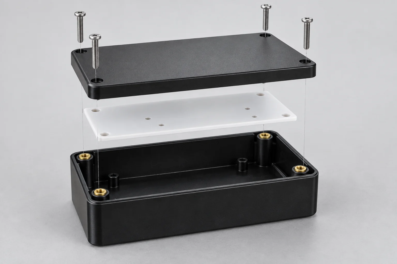
Bring the component drawing, hardware list and finished-unit requirements into one manufacturing review.
| Project input | Assembly scope for review |
|---|---|
| Assembly type | Mechanical assemblies, subassemblies and finished custom components. |
| Component supply | CNC machined plastic parts, purchased hardware and approved customer-supplied components. |
| Joining methods | Mechanical fastening, insert installation, controlled press fits, designed snap fits and compatible bonding. |
| Hardware | Screws, threaded inserts, pins, shafts, bushings, bearings, brackets, gaskets and seals. |
| Engineering inputs | Assembly drawings, 3D CAD, BOM, revisions and work instructions. |
| Materials | PEEK, POM, Nylon, polycarbonate, acrylic, ABS, PVC, PTFE and other reviewed engineering plastics. |
| Order stages | Prototype fit checks, pilot batches, low-volume orders and repeat production. |
| Acceptance | Part dimensions, assembly fit, visual condition and specifically agreed functional checks. |
| Process availability | Special joining, leak, pressure or instrumented functional testing requires confirmation in the quotation. |
Plastic assembly combines two or more plastic or mixed-material components into a functional unit. The connections may use screws, inserts, press fits, snap features, compatible adhesives or a combination of methods.
The deliverable is an assembled product or subassembly rather than a collection of individually machined parts. Examples include an enclosure with a mounted bracket and removable cover, a manifold with fittings and seals, or a gear-and-shaft mechanism supported by polymer bearing blocks.
The manufacturing plan must account for material behavior, mating geometry, hardware, joining forces and inspection of the completed unit. An assembly drawing and controlled bill of materials help coordinate component sourcing, machining, revision control and final acceptance. Service conditions and maintenance access determine whether joints should be permanent or removable.
Select the connection around the polymer, load path, environment and need for future servicing.
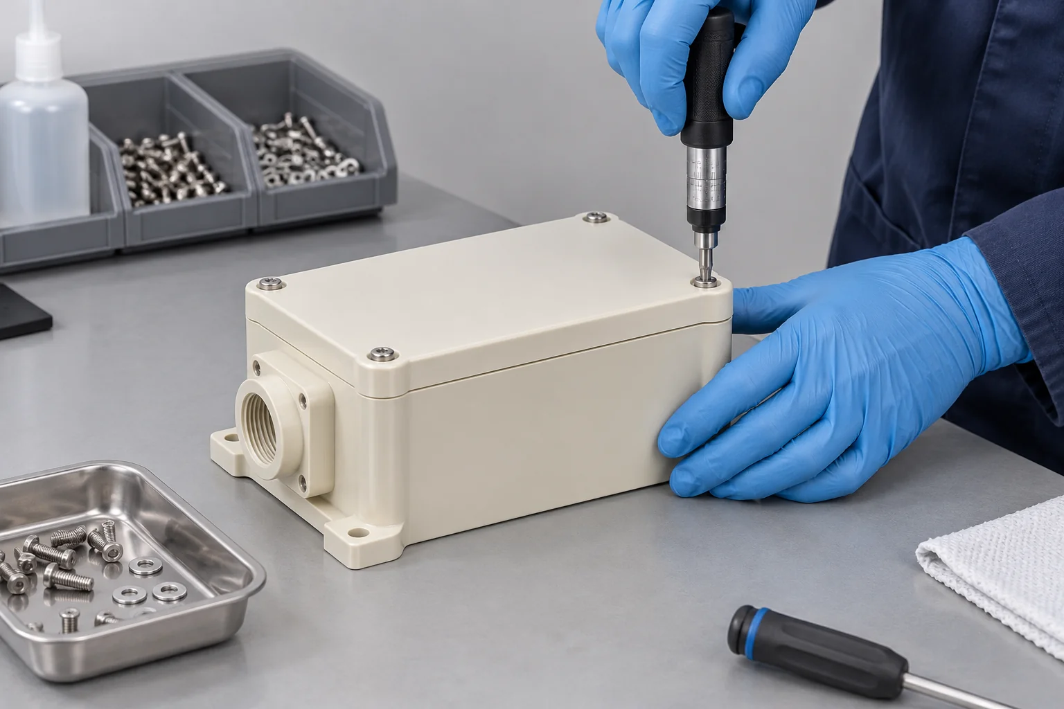
Screws, clips, pins and brackets connect components while allowing maintenance where the design permits. Define screw engagement, support faces and installation torque to avoid crushing a plastic boss.
Metal inserts provide a reusable threaded interface. Insert geometry, wall thickness and the polymer grade determine a suitable installation route. Heat, ultrasonic and press-in methods require individual compatibility and availability confirmation.
Controlled interference can retain pins, bushings and bearings. Review insertion force, local support, material stiffness, creep and dimensional changes before selecting the fit.
Designed flexible features engage without separate fasteners. Deflection, strain, engagement depth and expected assembly cycles must suit the actual polymer and geometry.
Compatible bonding can join housings, chambers and covers. Material identification, joint preparation, bond-line geometry and cure conditions must be qualified for the application.
Combine machined components, seals, bearings, brackets and hardware into a defined unit. The BOM and assembly drawing establish the correct parts, orientation and acceptance criteria.
Heat staking, ultrasonic welding and electromechanical integration are not assumed standard services. Discuss any such requirement before a manufacturing route is approved.
Choose the exact grade for the assembled conditions. Joining behavior can differ substantially from machining behavior.
| Material | Typical assembly use | Design consideration |
|---|---|---|
| PEEK | High-performance mounts and loaded components | Temperature, stiffness, fit and grade-specific behavior. |
| Delrin / POM | Gears, sliding parts and precision mechanisms | Low friction; adhesive joining can be difficult. |
| Nylon | Bushings, guides and flexible features | Moisture conditioning can change dimensions and stiffness. |
| Polycarbonate | Protective housings and transparent covers | Control fastener pressure and chemical stress cracking. |
| Acrylic / PMMA | Transparent chambers, covers and observation units | Brittleness, local stress and bonding compatibility. |
| ABS | Instrument enclosures and removable covers | Boss geometry, insert retention and snap-feature strain. |
| PTFE | Seals, liners and low-friction interfaces | Creep and low stiffness affect retained preload and interference. |
| PVC | Fabricated housings and fluid-related components | Grade, chemical exposure and joining compatibility. |
| Polypropylene / HDPE | Chemical-resistant guards and fabricated units | Low surface energy and thermal expansion complicate bonding and fit. |
| PVDF | Chemical-service components and fluid units | Grade purity, seal interfaces and qualified joining conditions. |
A material name alone does not establish chemical resistance, food-contact suitability or regulatory compliance for the complete assembly. Specify the grade, environment and required documentation for review.
Metal hardware adds threaded interfaces, locating features and structural connections. Design the interface to accommodate different stiffness and thermal expansion.
Define insert type, installation depth, surrounding wall and pull-out or torque requirements. Repeated service loads may govern the design.
Control alignment and retention while allowing for dimensional change. Chamfers and supported insertion help protect plastic bores.
Match the housing fit to the bearing or bushing specification. Confirm retained geometry after installation, rather than only measuring the free part.
Use suitable bearing surfaces, washers or compression limiters where needed. Specify the fastening sequence and preload or torque requirements.
Locate brackets from defined datums and avoid forcing misaligned holes together. Slotted features may accommodate movement when the design allows.
Review groove geometry, compression, surface condition and media compatibility. Sealing performance requires agreed assembly and test conditions.
Tolerance stack-up is the combined dimensional variation of the features that determine an assembly relationship. Individually acceptable components can still produce an excessive gap, interference or misalignment.
Specify clearance, transition or interference fits for the intended function. A nominal diameter without an agreed fit and inspection state does not define assembly behavior.
Relate mounting holes, bores and contact faces to a common datum scheme. Geometric variation may matter as much as individual size limits.
Consider the operating and inspection temperatures, especially where plastic and metal share a constrained interface. Moisture and loading may also change the relationship.
Check the assembled gap, alignment, movement or retained dimensions that control function. Free-part inspection alone cannot prove the complete unit will fit.
Illustrative worst-case example: three aligned dimensions A, B and C, each with ±0.10 mm variation, contribute up to ±0.30 mm to a directly additive stack. This is a simplified arithmetic example, not a TOPS manufacturing tolerance or a prediction for every assembly.
The actual stack depends on the geometry, signs, datums and constraints. Statistical analysis requires justified assumptions about distributions and process behavior. Review the functional limit first, then allocate tolerances to the dimensions that contribute to it.
Resolve assembly access, loading and inspection before the first components are machined.
Combine features where practical, while preserving machining access, repairability and material requirements. Fewer parts can reduce handling and stack-up contributors.
Identify the locating faces and features that establish component position. Make the intended contact sequence clear on the assembly drawing.
Plastic can deform or creep under sustained compression. Review boss support, contact area and compression-limiting features instead of relying on tightening force alone.
Match the insert and installation route to the resin, filler, wall thickness and service loads. Leave sufficient material around the receiving feature.
Check allowable deflection and strain for the actual grade. Brittle or heavily filled polymers may not tolerate a snap geometry suitable for an unfilled ductile material.
Review mixed-material constraints and temperature excursions. Provide movement where function permits rather than trapping expansion in a rigid joint.
Leave access for gauges and functional checks. Decide how hidden or inaccessible interfaces will be verified during the assembly sequence.
Specify removable connections, replacement items and permitted assembly cycles. Keep critical orientation or hardware choices unambiguous.
Assembly configurations for project review: match the arrangement to your drawing, materials and approved hardware.
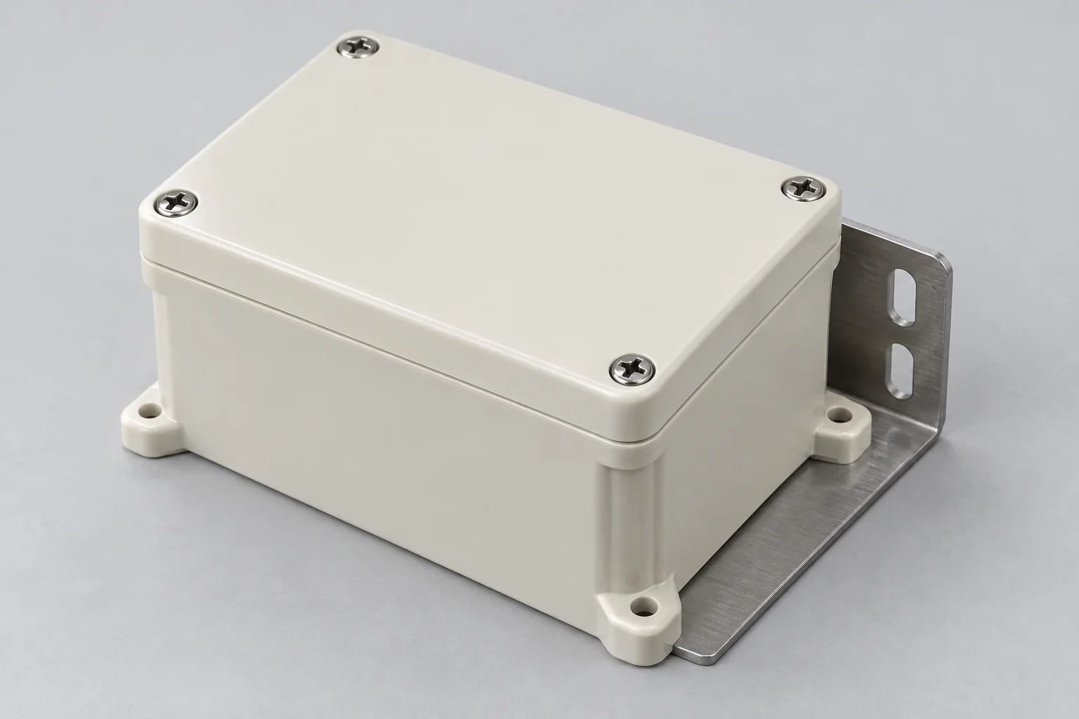
Machined housings, removable covers, threaded hardware and mounting brackets supplied as a coordinated unit.
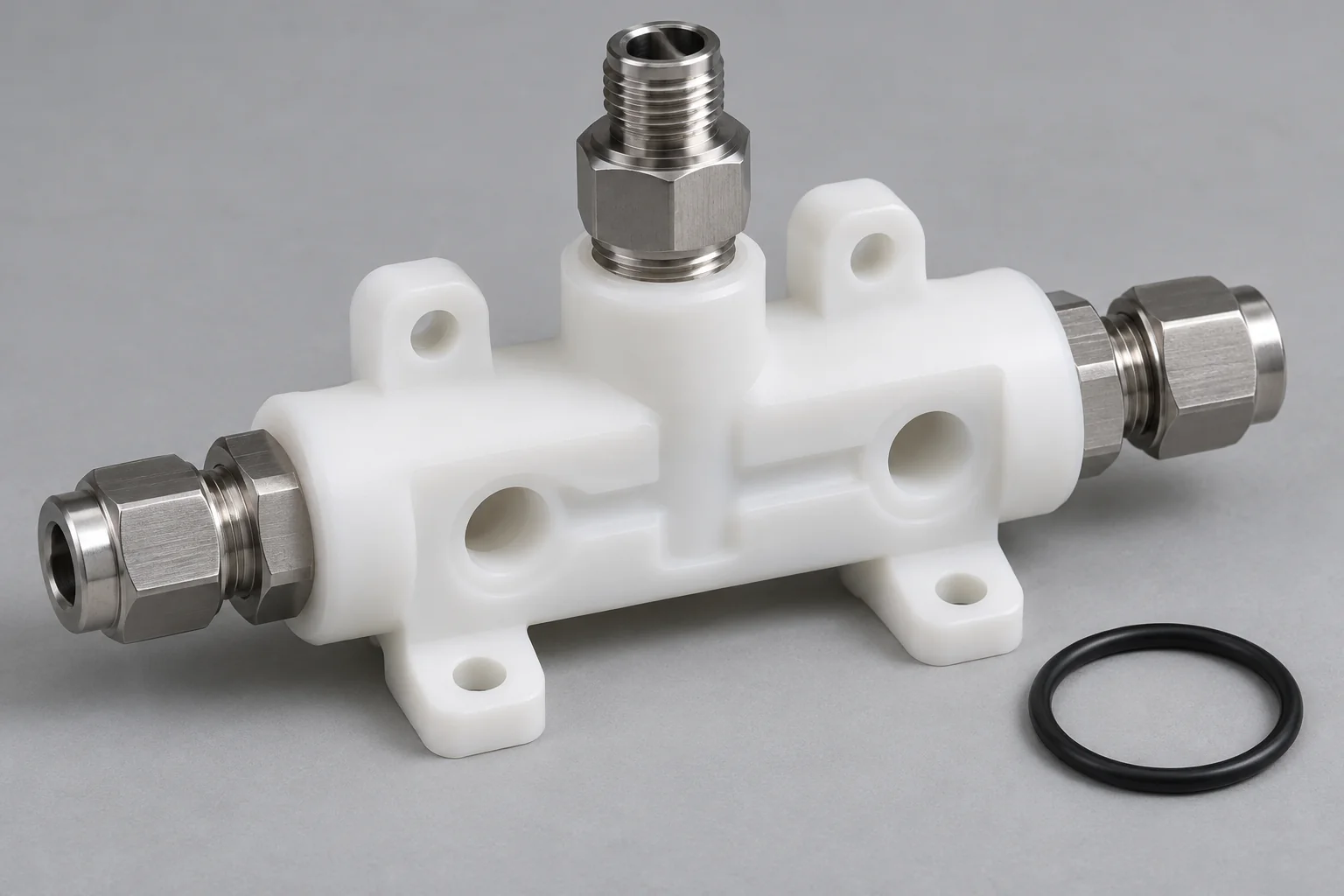
Machined blocks combined with selected fittings and seals. Define media, pressure and any required leak-test procedure.
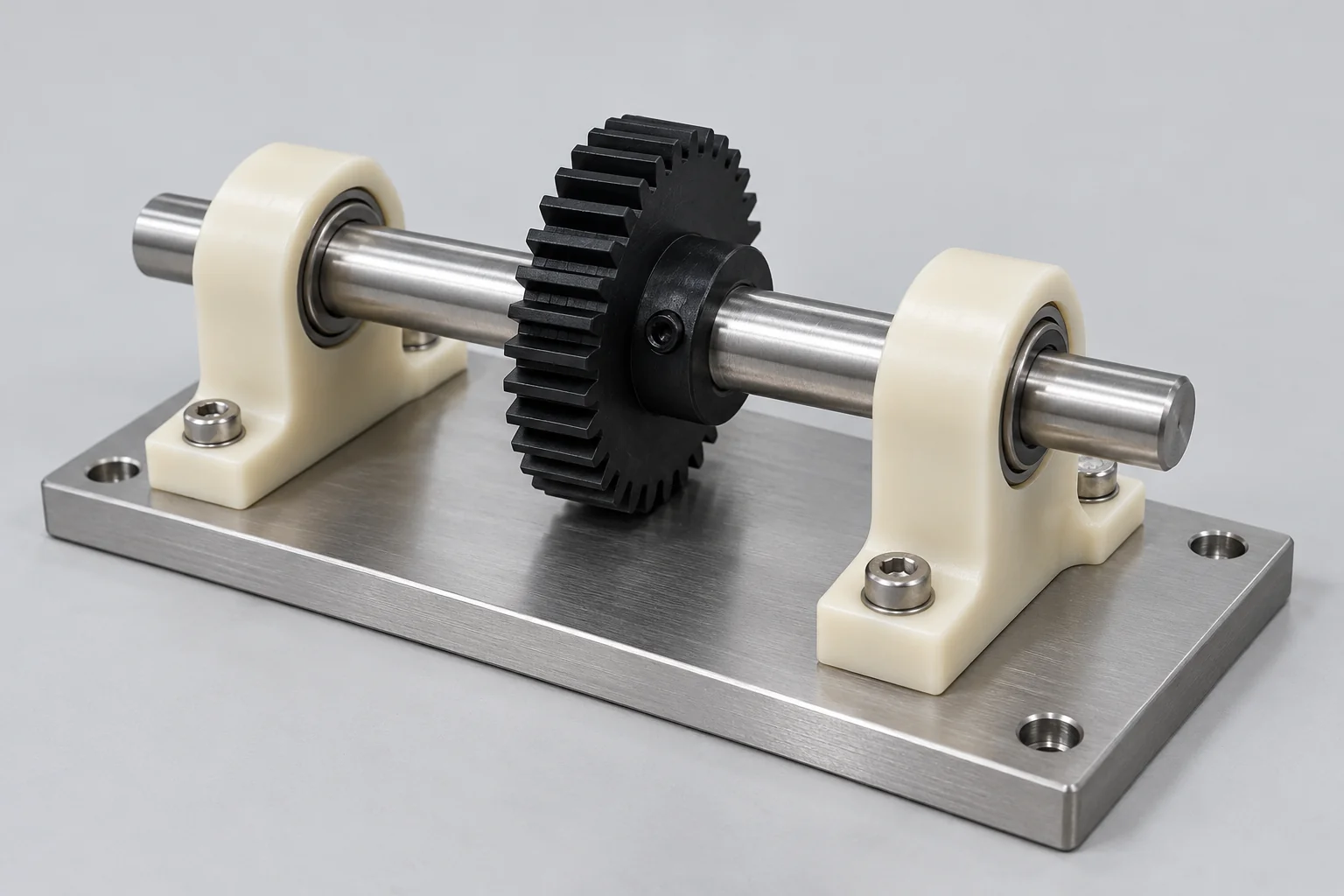
Gears, shafts, bushings and bearing supports assembled around specified alignment, clearance and motion requirements.
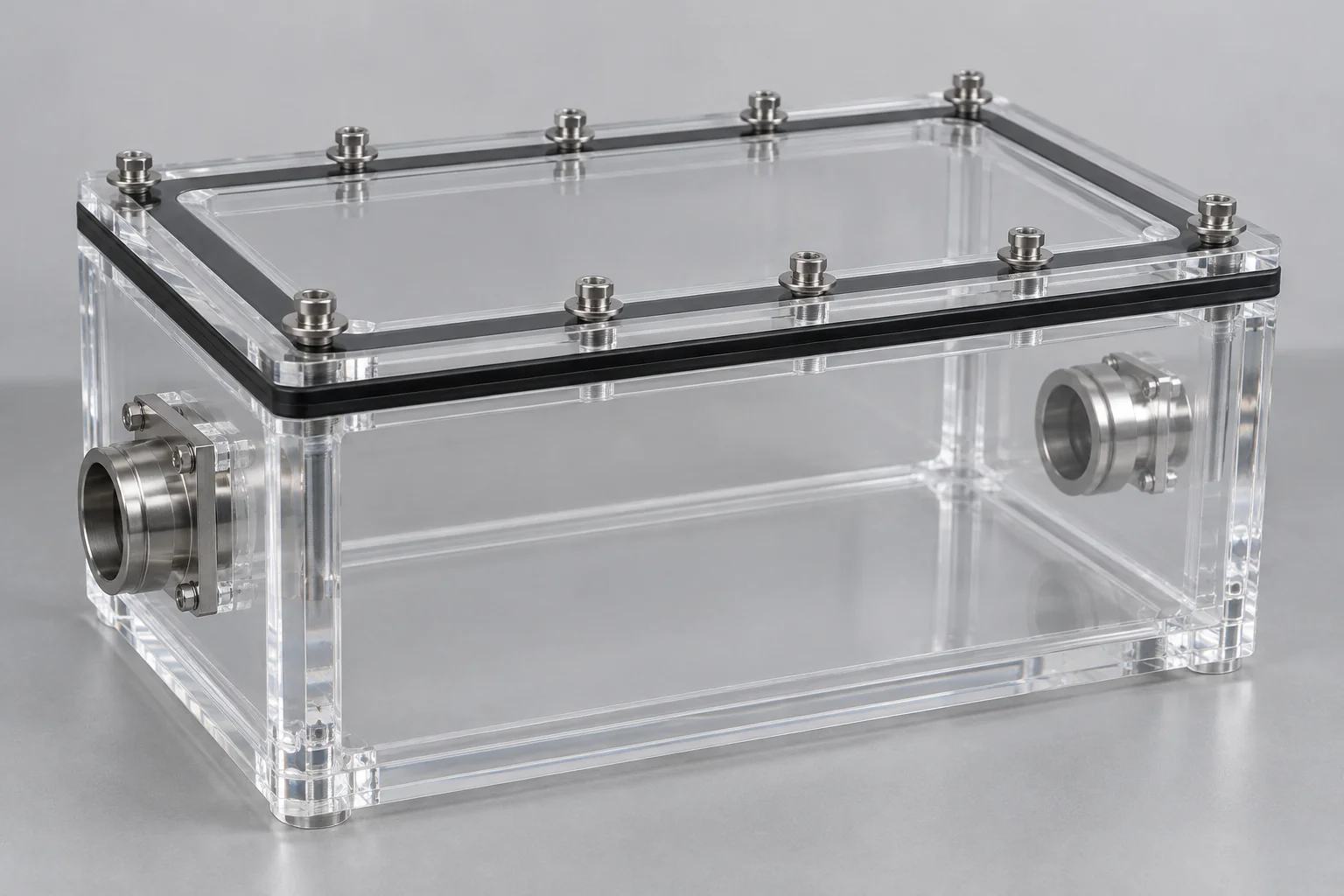
Observation chambers and covers with compatible joints or removable gasketed connections. Define cosmetic and viewing requirements.
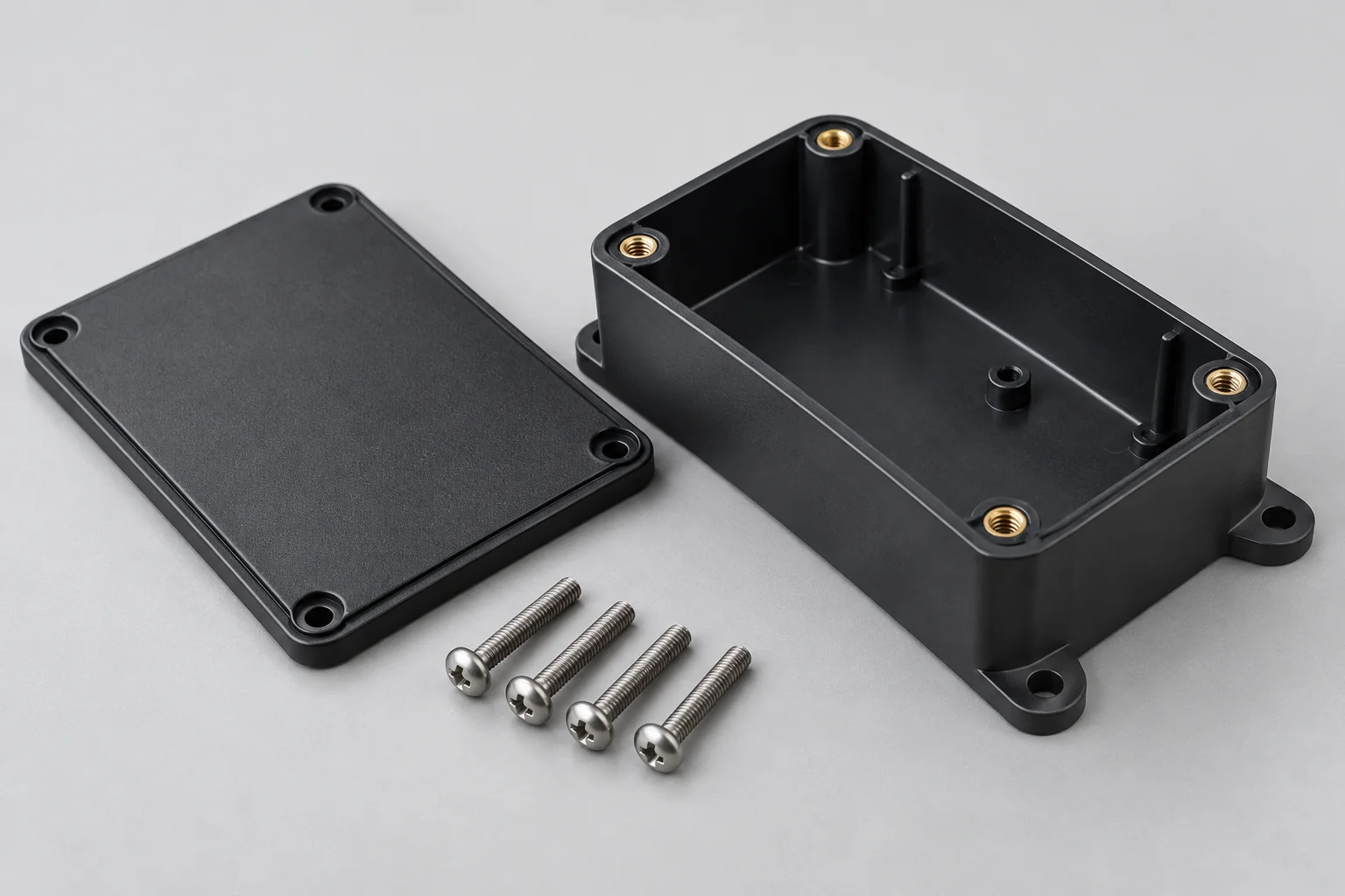
Custom enclosure bodies and lids integrated with approved hardware and internal mounting components. Electrical integration requires separate scope agreement.
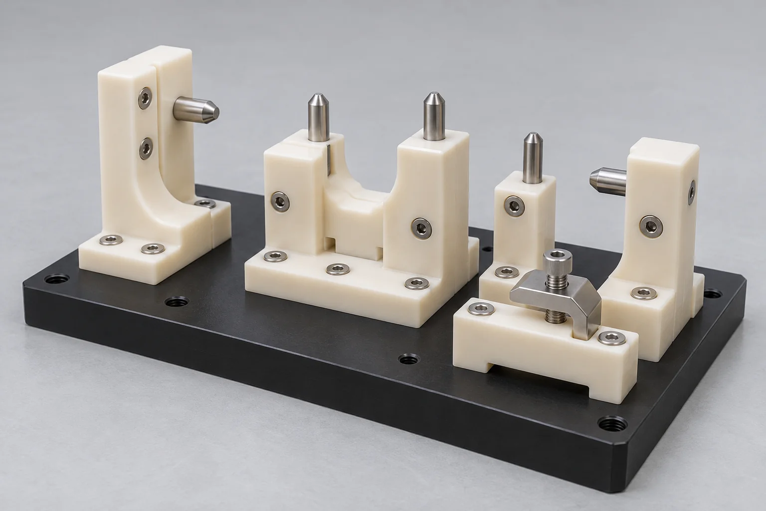
Jigs, locating blocks, insulation components and mounts with defined datums, hardware and final fit requirements.
A coordinated route connects machined geometry to the performance of the finished unit. Material choice, finish, mating features and inspection can be reviewed together.
Review CAD and assembly drawings.
Manufacture the plastic components.
Deburr and complete specified finishing.
Inspect critical component dimensions.
Prepare approved hardware and mating parts.
Assemble using the agreed sequence.
Verify final fit and specified function.
Protect, pack and deliver the assembly.
This reduces handoffs between component manufacture and integration, and makes it easier to resolve a fit issue before a full batch is completed. A defined release drawing and BOM remain essential: manufacturing and assembly must use the same approved revision.
Define acceptance for the complete unit as well as its individual parts. Inspection scope, equipment, sampling and records are agreed for the project.
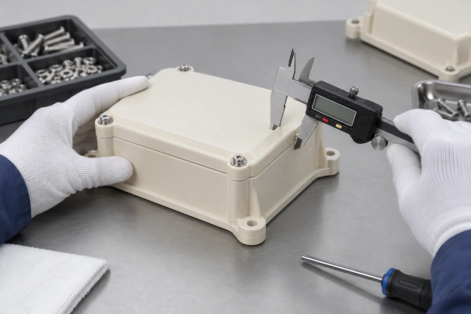
| Verification stage | What the plan may cover |
|---|---|
| Incoming components | BOM identity, material records and approved hardware. |
| Dimensional inspection | Critical sizes, datums and mating features before assembly. |
| Fit and alignment | Gaps, seating, interference and orientation after assembly. |
| Fastener verification | Correct type, length, engagement and installation sequence. |
| Torque verification | Specified torque where applicable, with an agreed procedure. |
| Functional checks | Required motion, engagement, access or operation. |
| Leak / pressure checks | Only when specified and the procedure and available equipment are confirmed. |
| Visual condition | Cracks, scratches, deformation, contamination and cosmetic acceptance. |
| Final release | Drawing revision, completed-unit requirements, identification and packing. |
A general assembly order does not automatically include pressure testing, certified torque records, cleanroom processing or regulatory qualification. Include any required test method, acceptance limit and report format in the RFQ so the scope can be confirmed before quotation.
Plastic bonding joins compatible surfaces. Plastic assembly integrates components into a functional unit and may include bonding as one of several connections.
| Factor | Plastic assembly | Plastic bonding |
|---|---|---|
| Scope | Complete unit or subassembly | Specific joint or bonded interface |
| Methods | Fasteners, inserts, press fits, snaps and compatible bonding | Compatible adhesive, solvent or separately qualified bonding process |
| Objective | Correct component integration and function | Required joint strength, integrity and appearance |
| Components | Plastic, metal, seals and approved purchased parts | Compatible mating materials and prepared surfaces |
| Inspection | Dimensions, fit, hardware and agreed function | Joint condition and specified strength or sealing checks |
| Serviceability | Removable or permanent, depending on design | Often permanent; depends on joint design |
| Example | Enclosure with cover, brackets and hardware | Bonded transparent chamber interface |
Keep the assembly definition controlled as the order develops.
Check fit, access, sequence and intended function before freezing the design. Record changes to interfaces and hardware in the released drawing and BOM.
Use suitable fixtures, instructions and component controls for a small batch. Agree sampling and any first-article approval before completing the order.
Control revisions, approved purchased parts, assembly instructions and inspection requirements. Review changes to material grades or hardware before substitution.
Application examples guide the engineering review; suitability depends on the specified material, environment and acceptance requirements.
Precision fixtures, insulation components and mounts using reviewed polymer grades and hardware.
Mechanical housings and equipment subassemblies to the supplied specification. Regulatory and cleanliness requirements need explicit agreement.
Guides, motion components and mixed-material mounts with defined clearance and alignment.
Enclosures, brackets and insulation components with approved fastening and access requirements.
Manifolds and fitted components with media-compatible seals and specifically agreed verification.
Wear-related mechanisms, mounting assemblies and serviceable equipment components.
Transparent chambers, observation covers and instrument components with defined chemical and cosmetic requirements.
High-performance polymer subassemblies reviewed against the customer drawings and documentation requirements. No certification is implied.
The engineering review goes beyond individual dimensions to consider how the complete unit will be manufactured, joined and accepted.
Coordinate component machining and the assembly interfaces within one project discussion.
Review moisture, creep, thermal expansion and local stress alongside the material specification.
Plan the relationship between plastic parts, metal hardware, bearings and seals.
Identify critical fits, assembly access and dimensional relationships before manufacture.
Carry approved geometry, BOM and inspection requirements into subsequent batches.
Agree what must be checked on the assembled unit and which records are required.
Final performance depends on material behavior, geometry, joining forces, hardware and operating conditions. Provide the functional requirements so our team can review the proposed route and confirm the quoted scope.
A controlled drawing and BOM connect each stage from quotation to shipment.
Upload assembly drawings, CAD and the BOM. Include revision identifiers and the finished-unit requirements.
Confirm materials, component sources, quantity and specifications. Identify any customer-supplied parts and restrictions on substitutions.
Review fit, tolerance stack-up and assembly access. Resolve critical interfaces and inspection conditions before release.
Plan component manufacture, purchasing and assembly. Confirm special processes and tests before committing to the route.
Manufacture the plastic components to the approved drawings. Complete the specified deburring and surface finishing.
Inspect individual parts and approved hardware. Check the features needed before they become inaccessible.
Install inserts, fasteners and other hardware. Follow the approved orientation and installation sequence.
Complete the subassembly or finished unit. Protect cosmetic surfaces and avoid forced fit during integration.
Verify final fit and required function. Record the agreed results and resolve nonconforming interfaces.
Identify, protect, pack and ship the released assembly. Use packaging suited to its surfaces and installed components.
Plastic assembly combines plastic and other components into a functional unit using suitable fastening, fitting or compatible bonding methods. The assembly drawing and BOM define the finished arrangement.
Request review of mechanical fastening, insert installation, press fits, designed snap fits, compatible bonded connections and multi-component subassemblies. Availability of special joining or testing is confirmed for the project.
Yes, mixed-material assemblies can include inserts, pins, shafts, brackets, bearings and screws. Different stiffness and thermal expansion must be considered at the interfaces.
Assembly covers component integration and finished-unit function. Bonding addresses a joined interface and can be one operation within a larger assembly route.
Threaded insert installation can be reviewed against the insert specification, polymer and surrounding geometry. Confirm the installation method and required retention or torque performance before manufacture.
We review the functional relationship, contributing dimensions, datums and inspection state. The drawing must define the required assembled gap, alignment or fit; an additive arithmetic example does not establish a universal capability.
Suitability depends on grade-specific allowable strain, stiffness, temperature and the feature geometry. Ductile unfilled materials may behave differently from brittle or filled grades. Validate deflection and expected assembly cycles.
Customer-supplied components can be considered after review of identification, quantities, condition and specifications. Agree responsibility for incoming acceptance, shortages and replacement parts.
Specified functional checks can be reviewed during quotation. Leak, pressure, instrumented torque and other specialized testing require confirmation of the procedure, equipment and acceptance criteria.
Prototype, low-volume and repeat-order routes can be reviewed. Controlled drawings, BOM revisions and approved inspection requirements support the transition between order stages.
ONE BOM. A CLEAR ASSEMBLY PLAN.
Send us your assembly drawing, 3D CAD files, bill of materials and production requirements. Specify materials, joining methods, hardware, critical fits, quantity and inspection requirements. Our team can review the manufacturing and assembly approach before quotation.
Include component sources, annual demand, GD&T, required functional or leak tests, documentation and packaging in your drawing package or email. Company, name, email and phone are required; country, part number, quantity and drawing upload are optional. Combine CAD, BOM and instructions in a ZIP when needed.
info@tops-precision.comSTEP / STP / IGES / X_T / DWG / DXF / PDF or ZIP, maximum 10 MB. Larger packages can be shared by email. Agree confidential-file handling before sending sensitive drawings.