Excellent Optical Clarity
Clear grades are useful for viewing and light transmission. Define the actual optical test if the part must do more than look transparent.
CLARITY STARTS WITH THE DRAWING.
TOPS Plastics manufactures custom Acrylic and PMMA components from your CAD files and engineering drawings. We review windows, light guides, covers, housings, manifolds and precision clear parts around their dimensions, appearance and intended use.
CNC milling, routing, turning, drilling and cutting support the primary process route. Polishing, bonding and assembly are confirmed for the selected stock and geometry.
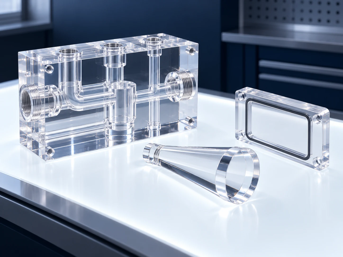
Your drawing, optical requirements and stock selection define the quotation. Process details and acceptance criteria are agreed for each component.
| Capability | TOPS Plastics project review |
|---|---|
| Material | Acrylic / polymethyl methacrylate (PMMA), with exact supplier designation. |
| Processes | CNC milling, routing, turning, drilling and cutting, selected around the geometry. |
| Secondary processes | Polishing, bonding and assembly where suitable; method and availability confirmed before quotation. |
| Material types | Cast or extruded PMMA in suitable sheet, plate, rod or blank forms. |
| Typical parts | Windows, covers, light guides, manifolds, housings and transparent fixtures. |
| Production | Prototype, low-volume and repeat orders with a defined inspection plan. |
| Files | STEP / STP, IGES, X_T, DWG, DXF and PDF, including units and drawing revision. |
| Inspection | Dimensional checks plus agreed visual, cosmetic and any optical acceptance. |
Acrylic is the common name for PMMA, or polymethyl methacrylate: a rigid thermoplastic widely selected for transparent parts, clean appearance and useful light transmission.
PMMA can be machined into clear windows, housings, light guides, manifolds, optical fixtures and display components. Suitable grades provide weather resistance and lower weight than glass for an equivalent volume.
Transparency is not the same as an optical specification. Grade, thickness, machining, finishing and the viewing geometry all influence the result. Compared with typical uncoated polycarbonate, acrylic usually has a harder surface but is more brittle; concentrated loads and incompatible chemicals need particular attention.
Technical references: Plaskolite OPTIX acrylic material families
PMMA is a practical choice when the visible surface is part of the component’s function. Select it alongside the load and environmental requirements.
Clear grades are useful for viewing and light transmission. Define the actual optical test if the part must do more than look transparent.
Generally harder than uncoated PC. Protective handling is still needed; coatings and grades can change the comparison.
Consider acrylic for a lighter transparent component, while reviewing thickness, support and deflection.
Outdoor suitability depends on the supplied grade, exposure and expected service life.
Suitable finishing can improve visible faces and edges. Agree a cosmetic reference and acceptance conditions.
Milling, routing, turning and drilling create custom details when tooling, heat, support and chip removal are controlled.
Technical references: PLEXIGLAS surface hardness guidance
Cast acrylic is often a useful starting point for complex, polished precision parts. Extruded sheet can suit simpler profiles and cost-sensitive panels. Confirm the actual grade and stock properties.
| Factor | Cast acrylic | Extruded acrylic |
|---|---|---|
| CNC machinability | Often preferred for complex pockets and precision features. | Practical for many routed profiles; cutting and heat control need review. |
| Internal stress | Stock history still matters; casting does not guarantee a stress-free blank. | Extrusion history can create stresses that need assessment. |
| Optical finishing | A common choice for demanding clear machined parts. | Finished quality depends on stock, geometry and the selected process. |
| Polishing | Review the faces and edges to be finished and subsequent assembly. | Review polish response and retained stress for the supplied stock. |
| Complex machining | Often a preferred route for substantial stock removal. | Consider a simpler profile or qualify the machining sequence. |
| Bonding | Joint preparation, fit and stress management remain important. | Compatible joint design and stress management are also required. |
| Cost | May cost more; check the actual size, grade and yield. | Can be more economical for standard sheet profiles. |
| Typical use | Precision blocks, cosmetic parts and complex clear components. | Flat panels and lower-complexity sheet components. |
Choose the stock route before approving the drawing. Include thickness variation, finish allowance and grade availability in the review. Neither material route eliminates the need to assess stress before finishing or bonding.
Technical references: OPTIX cell-cast fabrication guide · OPTIX extruded fabrication guide
Discuss Cast or Extruded Acrylic for Your Drawing →Use these families to describe your requirement. Availability, stock form and supporting documents are confirmed before an order; specialty grades are not assumed to be stocked.
A frequent candidate for precision transparent parts, polished blocks and complex machining.
Consider for simpler sheet profiles, panels and viewing covers after checking stress and thickness requirements.
Specify color, transmission, appearance reference and whether the part must remain see-through.
Confirm the outdoor exposure, expected life and grade-specific documentation.
Define wavelength, transmission, haze, surface condition and distortion where relevant.
Antistatic, impact-modified or other formulations are considered only where suitable machinable stock can be sourced.
A resin or sheet brand is not automatically an optical, medical or electrical qualification for the finished component. Specify the exact stock grade and required traceability.
Plan machining and finishing together. Access to a face or edge affects both dimensional control and appearance.
Pockets, blocks, housings, manifolds and fixtures with defined datums and viewing zones.
Explore this service →Profiles, panels, covers, windows and flat display parts supported during cutting.
Explore this service →Rings, sleeves, circular windows, spacers and cylindrical optical blanks.
Explore this service →Mounting and assembly holes require suitable edge distance, support and controlled breakout.
Prepare sheet profiles and blanks with practical allowances for later machining and finishing.
Agree the required appearance first. The specific finishing method and capability are confirmed for the geometry.
Transparent boxes, chambers and multi-part housings need joint, adhesive and stress review.
Explore this service →Mechanical, diamond, flame and other finishing methods are not interchangeable. We do not list an unverified vapor-polishing capability or promise a particular optical result without an agreed process and inspection method.
Acrylic is brittle and sensitive to stress concentrations. Poor tooling, heat or support can lead to chipped edges, smeared surfaces, whitening or delayed cracking.
Support the cut and avoid forcing thin features; PMMA usually tolerates impact less well than PC.
Excessive local heat can soften material and damage the edge or surface finish.
Rough holes and sharp corners can concentrate stress; review radii and load paths.
Machining, restrained geometry and assembly can leave stress that becomes important later.
Clear parts reveal scratches and tool marks, so clean contact surfaces and handling matter.
Separate optical, cosmetic and functional surfaces on the drawing. Each needs its own manufacturing and acceptance approach.
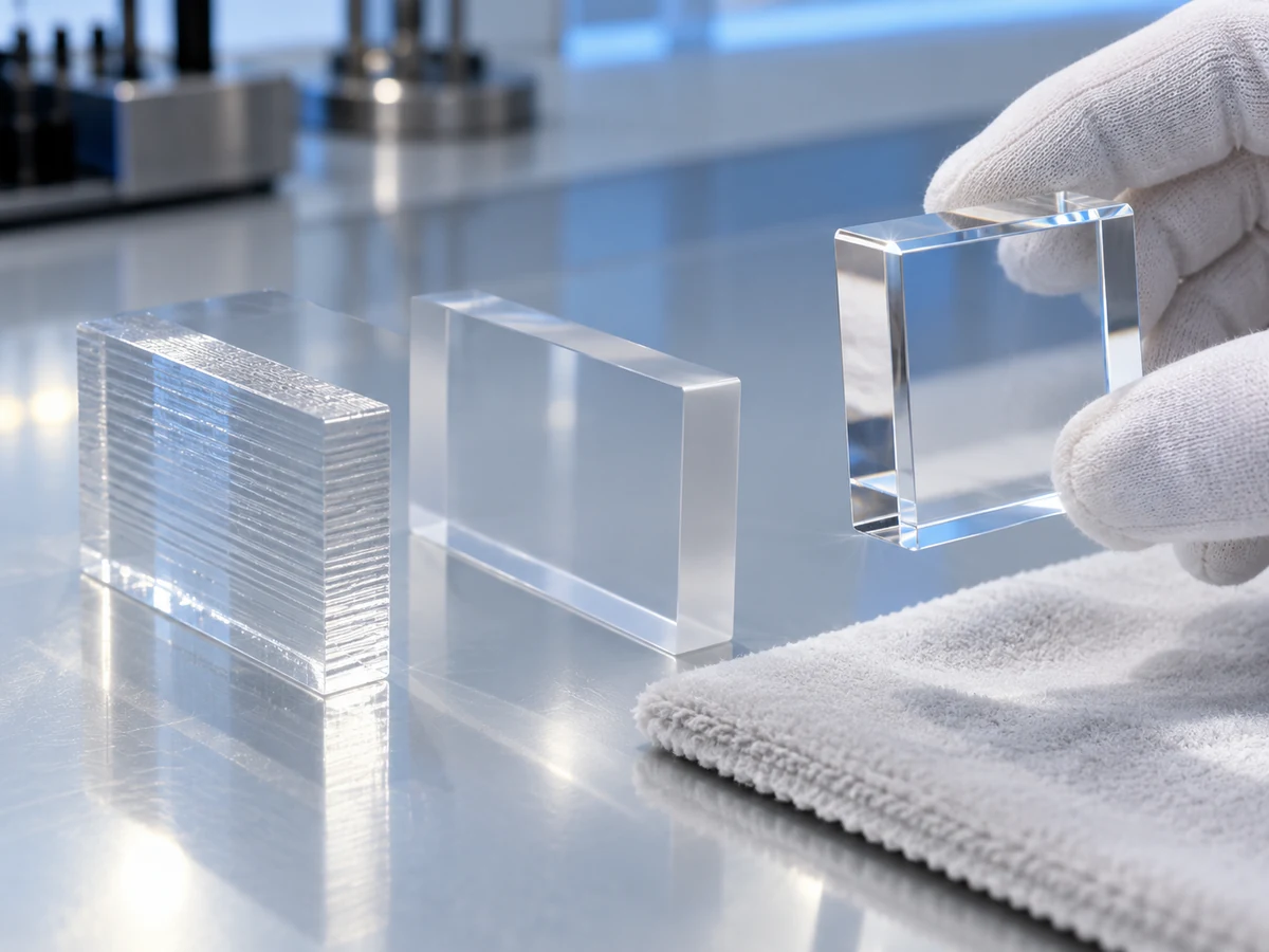
State the light path, wavelength or viewing use and any transmission, haze or distortion acceptance method.
Define viewing distance, lighting, acceptable marks and a reference sample or written criteria.
Prioritize dimensions, fits and datums where visible tool marks do not impair the function.
Identify edges that must remain visibly clear and how edge finishing may affect dimensions.
Not every acrylic face needs optical polishing. Limiting finishing to the surfaces that matter can reduce unnecessary cost and handling. A smooth-looking part still needs the agreed optical test if it serves as a light guide, window or lens.
Discuss Your Optical Requirements →Feasibility depends on size, geometry, stock type, stress, temperature, wall thickness, workholding and subsequent optical finishing. Send a drawing for feature-specific review.
| Feature | Main consideration |
|---|---|
| Precision bore | Wall thickness, brittle edges, mating fit and measurement method. |
| Large transparent panel | Thermal movement, flatness, support and mounting allowances. |
| Thin wall | Clamping, vibration, deflection and chipping after release. |
| Deep pocket | Tool access, heat, chip evacuation and wall balance. |
| Drilled hole | Exit support, edge breakout and distance from adjacent edges. |
| Optical face | Dimensional requirements separately from optical and cosmetic finish. |
| Bonded assembly | Joint fit, adhesive gap, alignment and movement during assembly. |
| Thread | Engagement, edge distance, tightening load and inserts where suitable. |
Crazing is a network of fine cracks that can develop when stress interacts with the environment. Material removal, assembly loads and incompatible cleaning chemicals should be reviewed together.
Limit local overheating and review signs of softened or damaged surfaces.
Avoid concentrated pressure or holding the part in a forced shape that changes when released.
Use practical radii and review stress at loaded transitions.
Check cleaners, adhesives, sealants and exposure duration against the stock supplier’s guidance.
Deburr and inspect hole edges; chips and rough transitions may start cracks.
Cracking may appear after machining or during bonding, installation or cleaning. First-article review should include the intended assembly and exposure conditions, not only a dimensional check on an unloaded part. Use supplier-approved cleaning procedures rather than assuming that a familiar solvent is compatible.
Technical references: OPTIX extruded fabrication and stress guidance
Annealing may be considered when substantial machining or later finishing, bonding or exposure makes residual stress important. It is a planned, grade-specific operation rather than a fixed step for every part.
The order may change for extruded stock, special grades, bonded assemblies or a different finishing route. Agree the procedure, support, cooling and reinspection requirements before manufacture. No universal temperature or holding time is published as a TOPS process capability.
Technical references: PLEXIGLAS machining and annealing guide
A useful drawing explains what must remain clear, what must fit and how the component will be assembled and cleaned.
Consider cast stock for complex polished or bonded components, subject to actual grade and blank availability.
Allow practical radii and review notches near loaded or thin sections.
Give mounting holes room for support and tightening loads; review edge distance for the actual size and load.
Review unsupported spans, vibration and risk of chipping or fracture.
Define viewing zones and functional datums independently, avoiding unnecessary finishing.
Identify as-machined, fine-machined, cosmetic-polished or optical edges and the acceptance criteria.
Plan joint geometry, alignment, adhesive gaps and stress management before fixing the part design.
Supply agent, concentration, frequency and temperature so compatibility can be assessed.
Each image illustrates a different component concept. Final dimensions, grade and acceptance are controlled by your approved drawing, not these images.
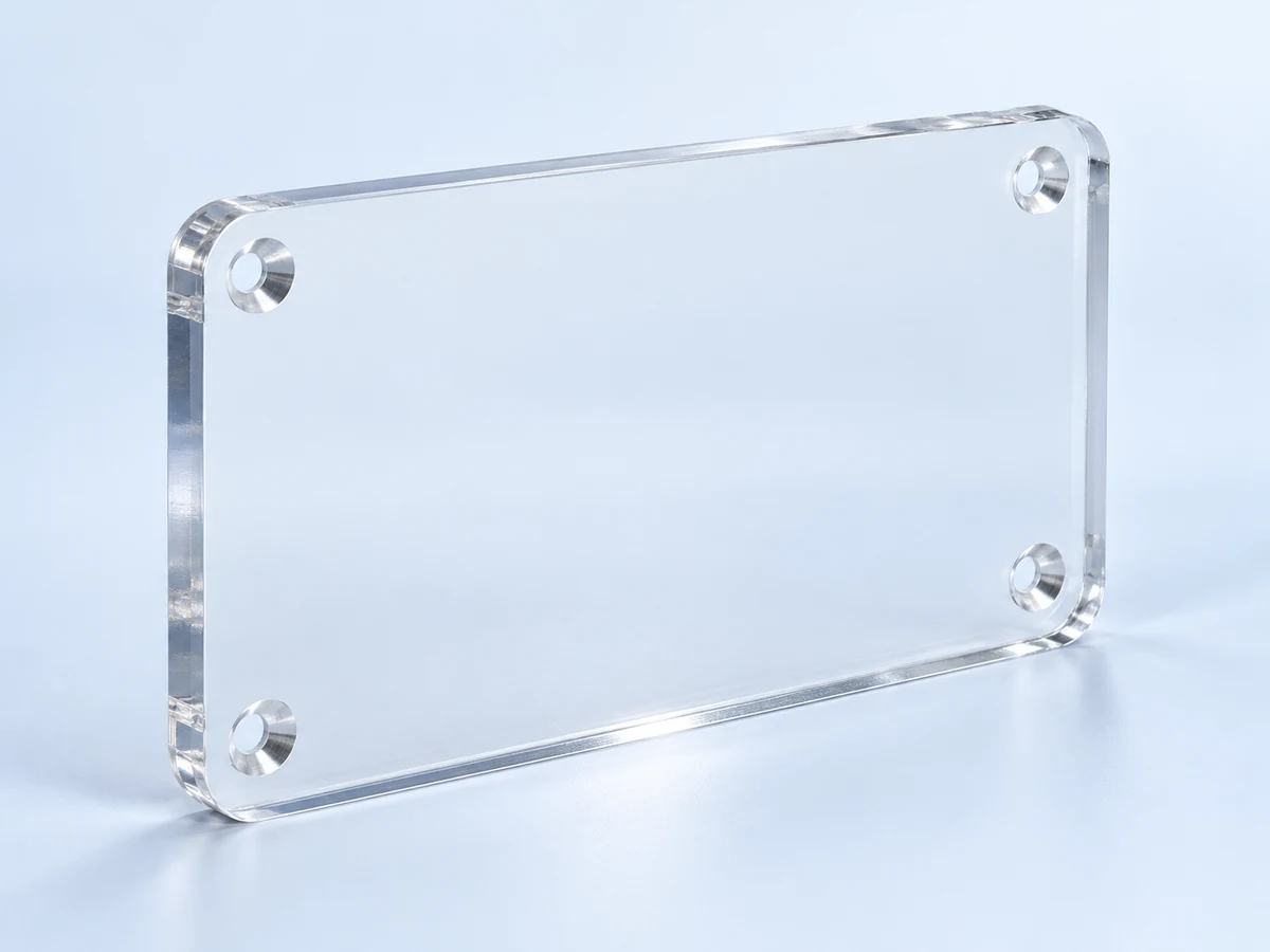
Clear viewing panels with mounting holes, defined flatness and protected faces.
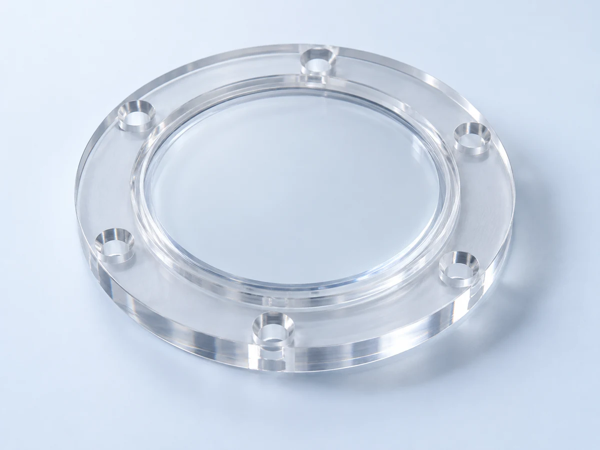
Circular or shaped observation windows with fit and viewing-zone requirements.
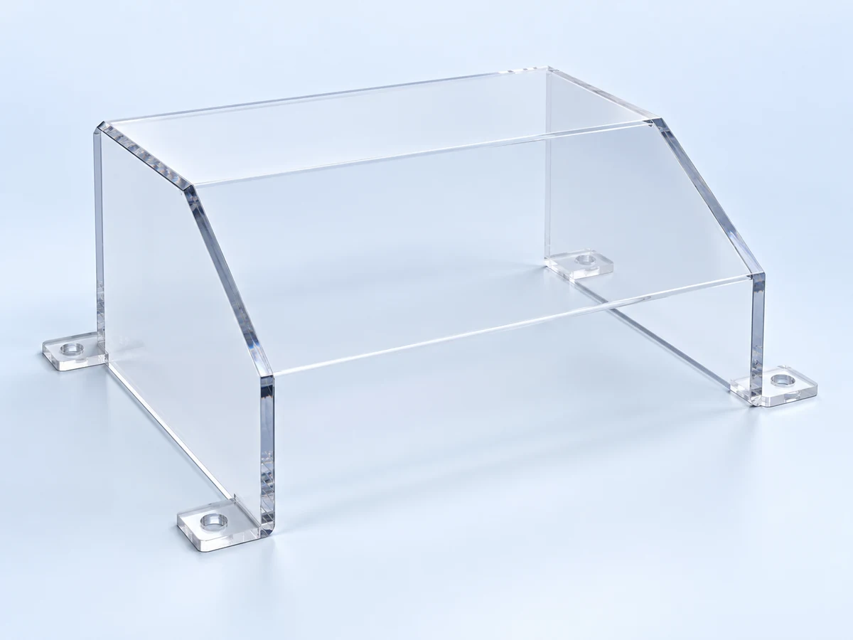
Profiled covers with mounting details, clearances and specified edge appearance.
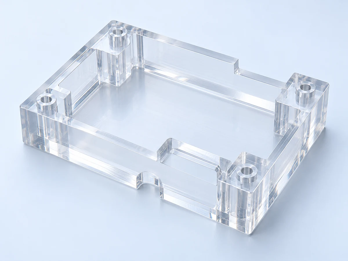
Pockets and interfaces combined with protected transparent faces.
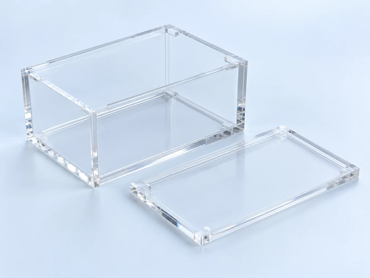
Multi-part bodies and lids with joint alignment and assembly review.
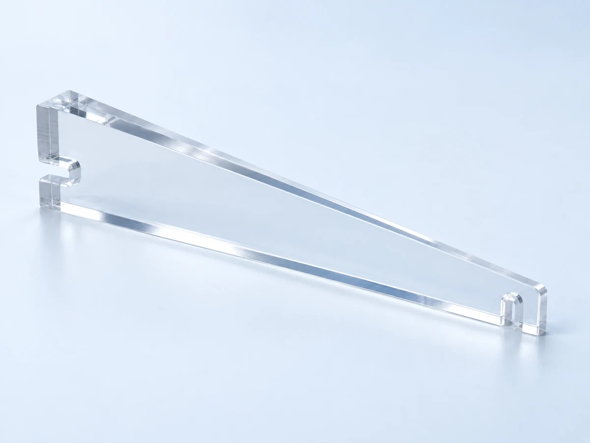
Tapered or cylindrical light-path components with specified optical acceptance.
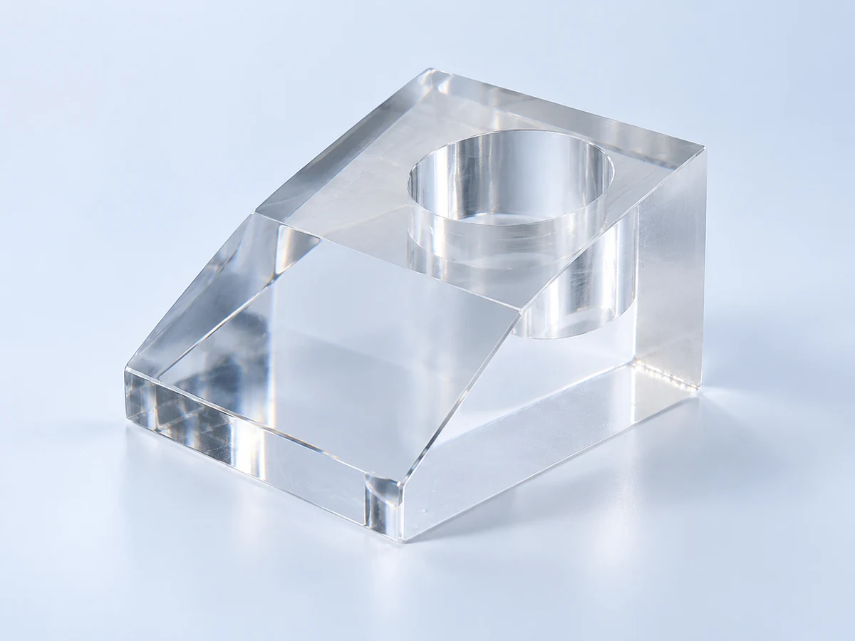
Thick clear blocks with machined features and defined viewing faces.
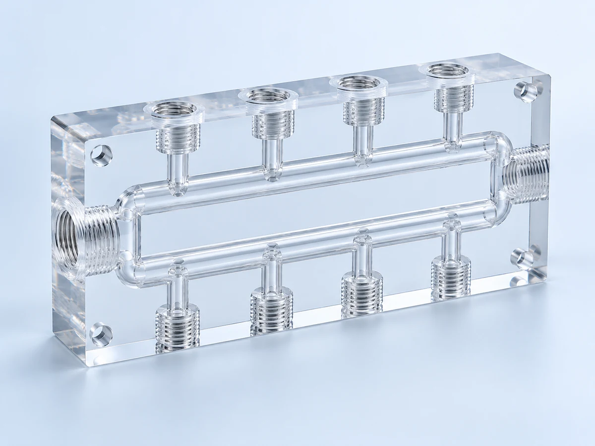
Transparent passages and ports for customer-defined fluid and pressure conditions.
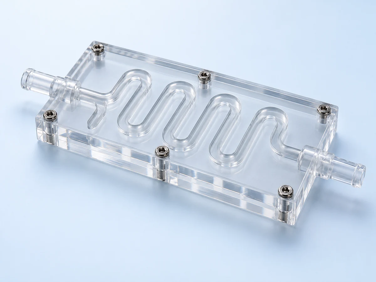
Observation channels and chambers with sealing, compatibility and test requirements.
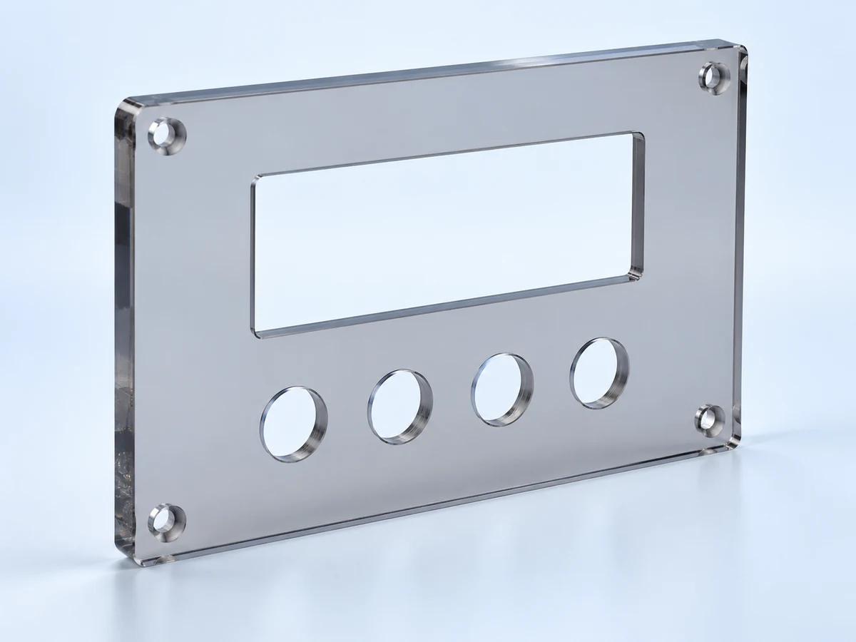
Routed instrument profiles with display openings and controls access.
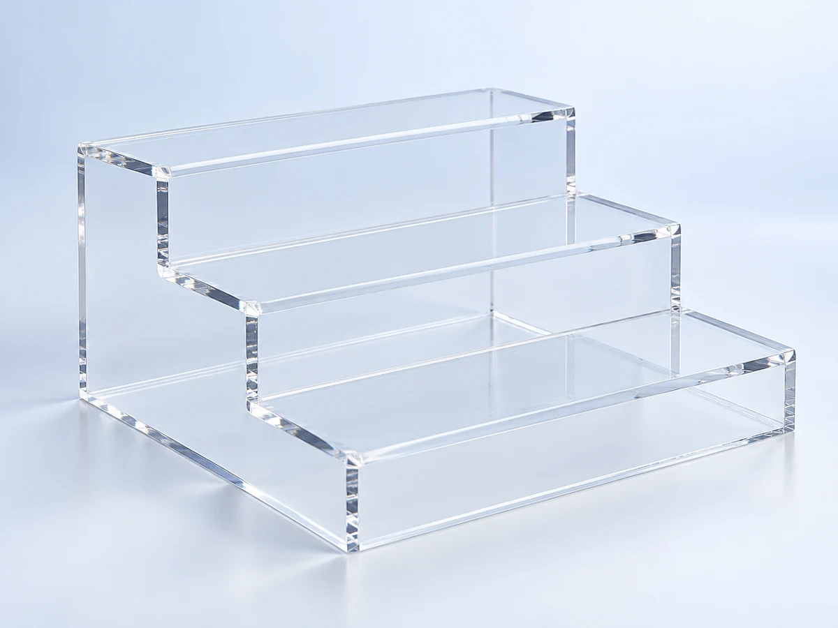
Clear supports and visual assemblies with cosmetic edge and face requirements.
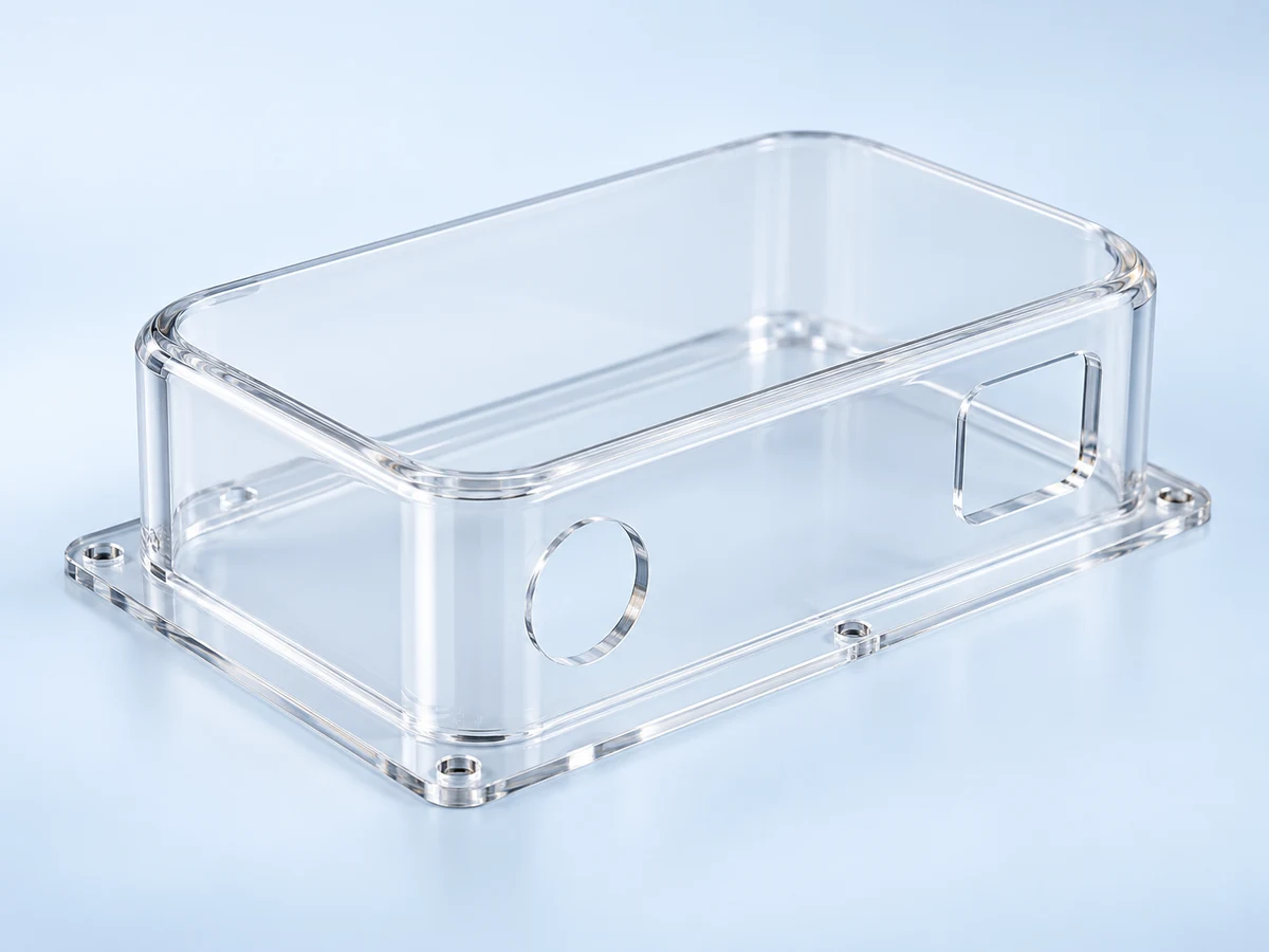
Equipment covers with mounting flanges and installation clearance.

Prototype lens geometries or blanks subject to surface, form and optical feasibility review.
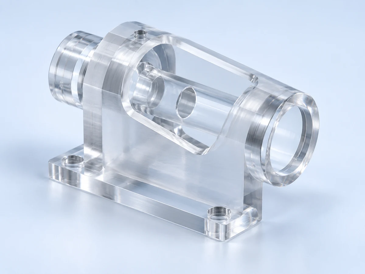
Transparent parts for validating fit, appearance and manufacturing choices.
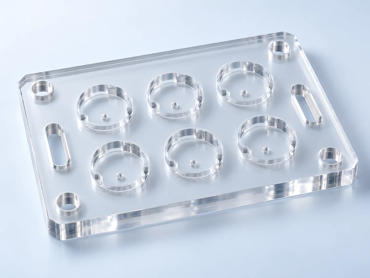
Locating plates and pockets for visual access during assembly or inspection.
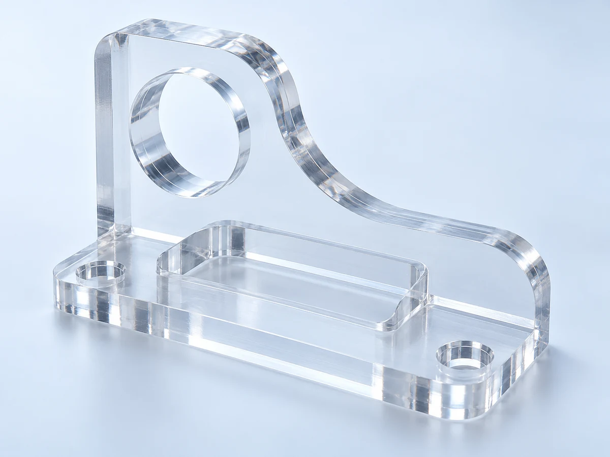
Drawing-based transparent parts with custom profiles, pockets and mounting features.
For transparent components, dimensional accuracy and visual clarity must be controlled separately. Mark critical optical faces before choosing machining, finishing and inspection.
Define the light path, coupling surfaces and required transmission or output behavior.
Specify viewing area, surface form and any distortion or haze requirement.
Separate clear viewing zones from mounting edges and functional features.
Define visibility, fluid compatibility, temperature, pressure and seal interfaces.
Review internal passages, wall sections, port loads and leak-test scope.
Coordinate clear joints, access openings and any required containment performance.
Identify display apertures, mounting clearances and visible surface acceptance.
Agree cosmetic references, illumination and the appearance of polished edges.
A clear machined blank is not automatically a precision optical lens. Lens form, surface quality and optical performance require separate feasibility and test agreements.
Choose the finishing scope by surface function. Improvements in appearance must be balanced with dimensions, stress and later assembly.
| Finish | Typical purpose | Project review |
|---|---|---|
| As-Machined | Functional features where visible tool marks are acceptable. | Define burr and edge requirements. |
| Fine Machined | Cleaner appearance without a full polishing route. | Agree tool-mark limits and a reference surface. |
| Mechanical Polish | Selected cosmetic surfaces or edges. | Confirm access, shape retention and method availability. |
| Diamond Polish | Clear edges on suitable accessible geometry. | Availability and edge geometry are confirmed before quotation. |
| Flame Polish | Specific compatible geometry and applications only. | Thermal stress and later bonding must be reviewed; not assumed as a general capability. |
| Optical Finish | Defined transparent or light-path performance. | Specify the optical acceptance method and validate the route. |
Polishing can improve appearance while introducing or exposing stress if poorly controlled. A glossy edge is not evidence of a stress-free part. Agree a finishing sample and consider later bonding, cleaning and inspection before approving repeat production.
Technical references: PLEXIGLAS sanding and polishing guidance
Plan the joint as part of the design. Bonding can reveal residual stress, and a transparent seam has visual requirements as well as structural ones.
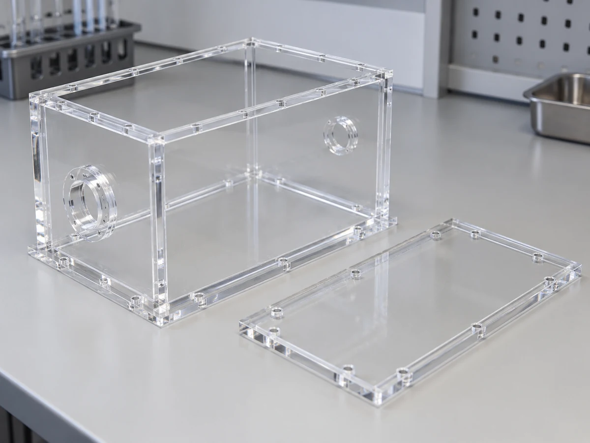
Only use a compatible, agreed process after reviewing stock stress, fit and intended exposure.
Specify adhesive compatibility, gap, cure conditions and required joint performance.
Review hole clearances, washers, support and torque to avoid concentrated stress.
Assess insert type, retention method, edge distance and the load introduced into the PMMA.
Coordinate alignment, seam appearance, access and final inspection of the complete assembly.
Boxes, laboratory chambers, clear housings, manifolds and covers may use different joint strategies. A bonded or screwed assembly is not automatically leak-tight or pressure-rated; specify the required test and operating conditions. Availability of a particular bonding process is confirmed in the quotation.
Technical references: PLEXIGLAS bonding guidance
Inspection should cover dimensional function and the visible quality that makes PMMA useful. The scope and records are agreed with your requirements.
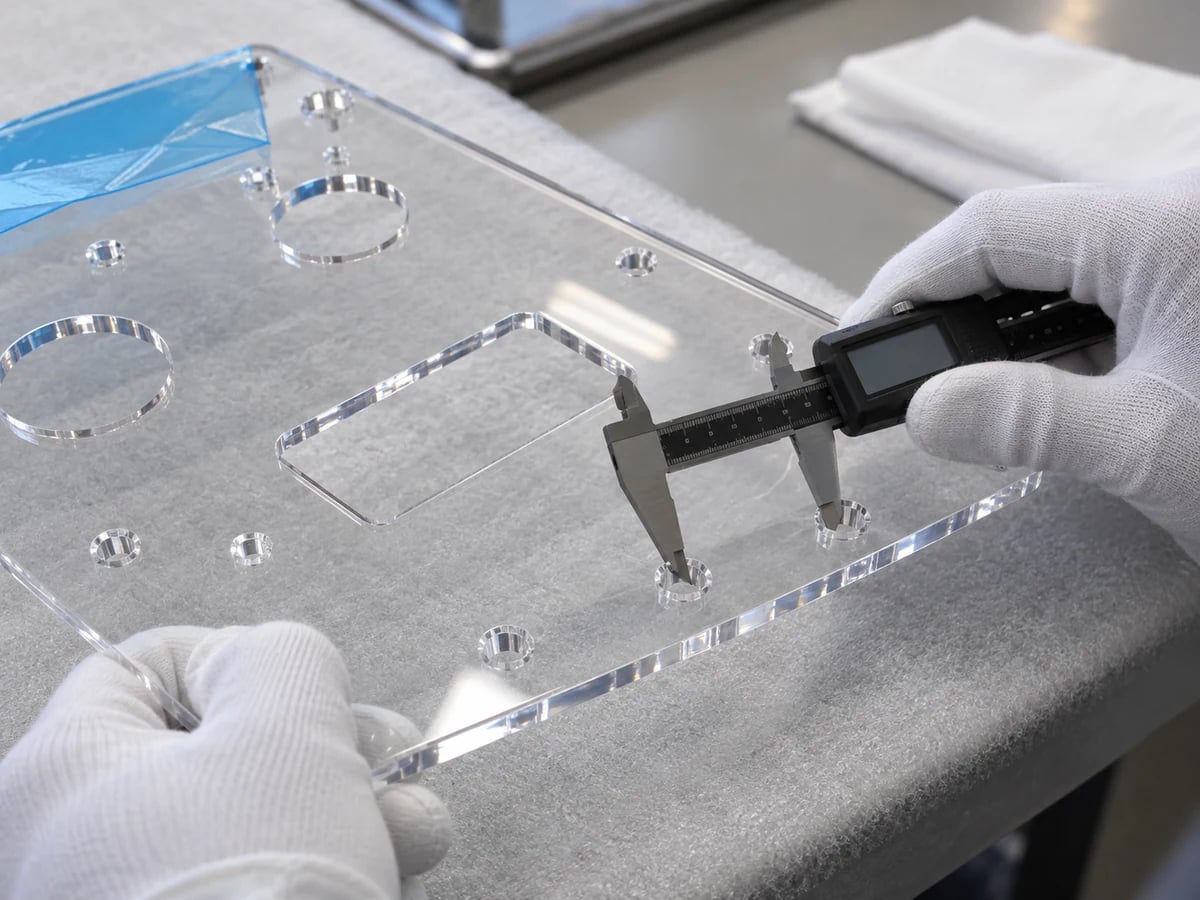
Visual checks may include scratches, haze, cracks, chips, bubbles at joints, polishing marks and edge clarity. Agree viewing conditions and acceptance samples. For optical performance, define the test rather than relying on a photograph. Shipment inspection should also confirm that protective packaging will prevent contact damage.
Choose acrylic when clarity, polished appearance and uncoated surface hardness lead the decision. Consider PC when impact resistance and toughness are more important, subject to grade and application review.
| Factor | Acrylic / PMMA | Polycarbonate |
|---|---|---|
| Optical clarity | Frequently selected for clear visual and light-path components. | Clear grades available; verify optical requirements for the stock and finish. |
| Surface hardness | Generally harder than typical uncoated PC. | Coatings and grade choice can substantially change surface behavior. |
| Scratch resistance | Useful uncoated surface resistance, but scratches still require protection. | Uncoated PC can scratch more readily; evaluate coated options where needed. |
| Impact resistance | Review impacts carefully; PMMA is generally more brittle. | Often preferred for tough components and protective applications. |
| Brittleness | Edges, notches and mounting loads require care. | Typically better able to tolerate impact and concentrated deformation. |
| Polishability | Accessible faces and edges can be finished for appearance. | A different finishing route may be required; validate the result. |
| Light guides / displays | Often a useful starting point for visible and illuminated parts. | Useful where optical requirements must be balanced with toughness. |
| Safety guards | Suitability depends on the machine hazard and specified verification. | A frequent guard material option; the complete safeguard still needs validation. |
| Cosmetic appearance | Commonly selected for glossy clear and polished-edge assemblies. | Useful where appearance and mechanical toughness must be combined. |
Technical references: PLEXIGLAS surface comparison guidance
Explore Polycarbonate Machining and Fabrication →Application requirements determine grade selection, finishing and documentation. The material family does not establish regulated-use suitability.
Transparent covers, observation chambers and fluidic parts with cleaning and documentation requirements.
Optical blocks, windows and clear housings with defined viewing or light-path acceptance.
Display windows and transparent enclosures with mounting and environment review.
Inspection windows and sensor covers with installation loads and viewing-zone requirements.
Light guides and optical components defined by the intended illumination and performance test.
Covers and viewing windows selected for temperature, cleaners and support conditions.
Manifolds and flow-observation parts with chemical compatibility and agreed leak or pressure testing.
Transparent prototypes for fit, appearance, assembly and application validation.
Use early parts to establish the visual reference and assembly behavior as well as dimensions.
Validate appearance, transparency, dimensions, assembly and any required light transmission or application testing.
Explore this service →Approve the stock, finishing method and inspection scope for instruments, covers and specialized transparent components.
Control grade, revision, machining and finishing changes, with consistent visual references and protected packaging.
For acrylic parts, dimensional accuracy alone is not enough. Clarity, stress, edges and handling need to be considered throughout the manufacturing route.
Review brittle features, support and cutter access before agreeing the route.
Choose stock against geometry, finish and subsequent assembly.
Match the process to pockets, profiles and rotational features.
Identify viewing zones and acceptance criteria early.
Confirm the method, feasibility and finish reference per project.
Connect geometry, clamping, finishing, cleaning and assembly loads.
Use approved first articles and controlled revisions for repeat orders.
Agree measurement and appearance checks that reflect customer requirements.
Specific stock availability, optical capability, documentation, testing and delivery commitments are confirmed in the quotation. The illustrated concepts do not establish prior customer projects or measured TOPS production results.
The sequence connects the drawing to surface acceptance and a protected finished component. Approval points and conditional operations are agreed for the actual part.
Direct answers to PMMA stock, machining, polishing, crazing and transparent-part selection.
Yes. Acrylic is the common name for polymethyl methacrylate (PMMA). Exact grades, colors, coatings and stock routes can still have different properties.
They are different stock manufacturing routes. Cast acrylic is often preferred for complex precision machining; extruded sheet can suit simpler profiles. Confirm the actual grade, thickness and stress requirements.
Acrylic can be machined successfully, but brittleness, heat and surface protection require care. Tooling, support and chip removal must suit the part.
Yes. Milling produces pockets, profiles and multi-face details; turning suits circular features and cylindrical blanks. The geometry and optical requirements determine the route.
Reduce crack risks by reviewing stock, support, heat, corner radii, hole quality and assembly loads. No process can guarantee zero cracking without considering the actual design and exposure.
Suitable surfaces and edges can be finished for improved clarity. Access, geometry, stress and the required optical test determine feasibility; not every face needs polishing.
Residual stress can interact with loads or incompatible chemicals and cleaners, causing fine cracks. Review the complete machining, finishing, bonding and cleaning sequence.
Acrylic is often chosen for clarity and polished appearance; PC is often chosen for toughness and impact resistance. Select the exact grade for the function and environment.
Tolerance feasibility depends on geometry, size, stock, stress, temperature and finishing. Send the drawing for a feature-specific assessment rather than assuming one universal value.
Yes, where PMMA suits the intended function. Use prototypes to validate fit, appearance, assembly and any optical or environmental requirements before production.
YOUR DRAWING. YOUR SURFACE REQUIREMENTS.
Upload your CAD model or drawing and specify the grade, quantity, critical tolerances, optical or cosmetic requirements, edge finish, bonding requirements and application. Our team will review the machining, finishing and fabrication strategy before quotation.
Tell us whether cast or extruded stock is required and include operating temperature and cleaning or chemical exposure. Company, name, email and phone are required. All project details and both drawing uploads are optional.
info@tops-precision.comCAD and 2D drawing uploads: combined maximum 10 MB. Larger files can be shared by email. Agree confidential-file handling before sending sensitive drawings.