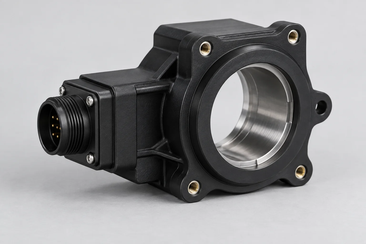
01
Plastic Housings
Sensor bodies, controller modules and connector interfaces with defined mounting datums and mating geometry.
Explore component details →
ELECTRICAL INTERFACES · ENGINEERED POLYMERS
TOPS Plastics manufactures custom CNC machined plastic components for electronic devices, control systems, sensors, connectors, PCB assemblies, power electronics, test equipment and industrial electrical systems. We machine PEEK, PEI/Ultem, PPS, POM/Delrin, PTFE, Polycarbonate and other engineering plastics according to customer CAD files, electrical requirements and dimensional specifications.
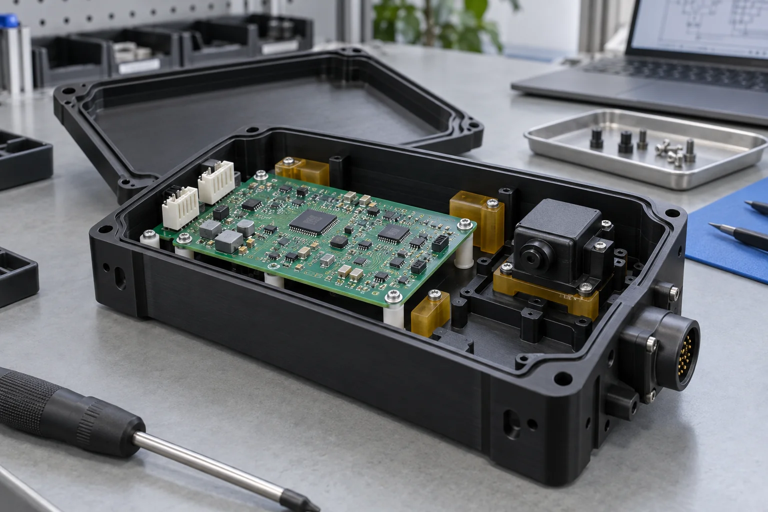
Start with the functional electronic interface, then define the polymer, manufacturing route and evidence needed for acceptance.
| Capability | TOPS Plastics |
|---|---|
| Typical parts | Housings, insulators, spacers, fixtures, manifolds and connector parts |
| Materials | PEEK, PEI, PPS, POM, PTFE, PC and customer-specified grades |
| Processes | CNC milling, turning, 5-axis machining, drilling and tapping |
| Key requirements | Electrical insulation, dimensional stability and heat resistance |
| Production | Prototype, low-volume and repeat production |
| Input | STEP, CAD, 2D drawings and reference samples |
| Inspection | Drawing-based dimensional inspection |
| Hardware | Inserts, pins, fasteners and assembly where specified |
Explore component families for electronic devices, power assemblies, controls and test equipment.
Sensor bodies, controller modules and connector interfaces with defined mounting datums and mating geometry.
Explore component details →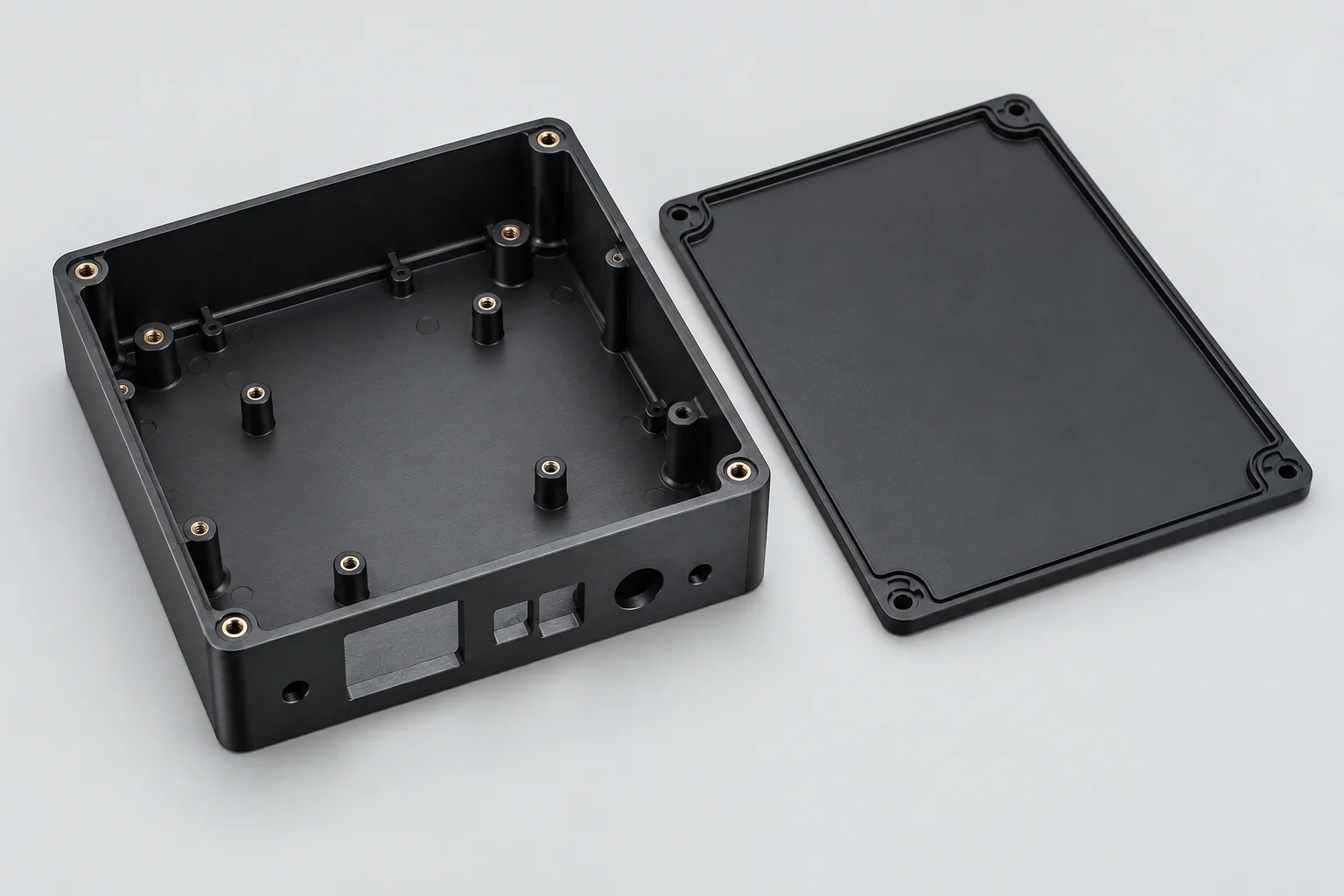
PCB, instrument, power/control and test-equipment cases with internal supports and accessible connector cutouts.
Explore component details →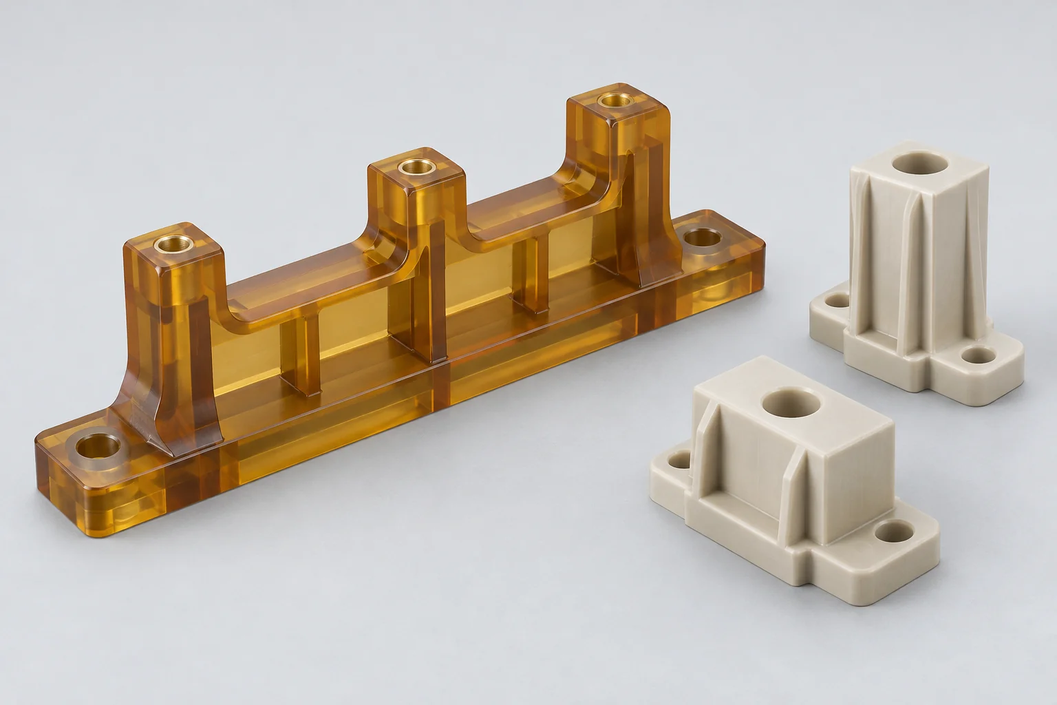
Electrical separation, busbar supports, connector isolation and barriers for customer-defined voltage conditions.
Explore component details →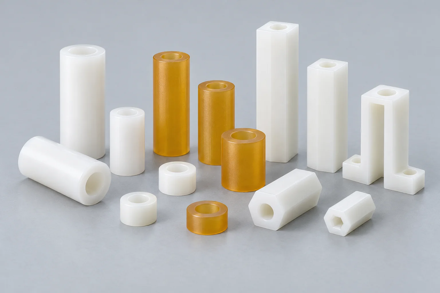
PCB spacing, standoffs and mechanical stack control with specified height, bore and insulating grade.
Explore component details →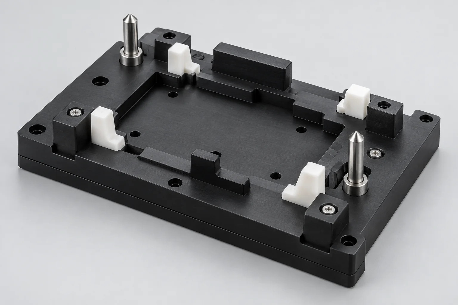
Assembly, inspection, connector insertion, PCB handling and test nests with repeatable locating features.
Explore component details →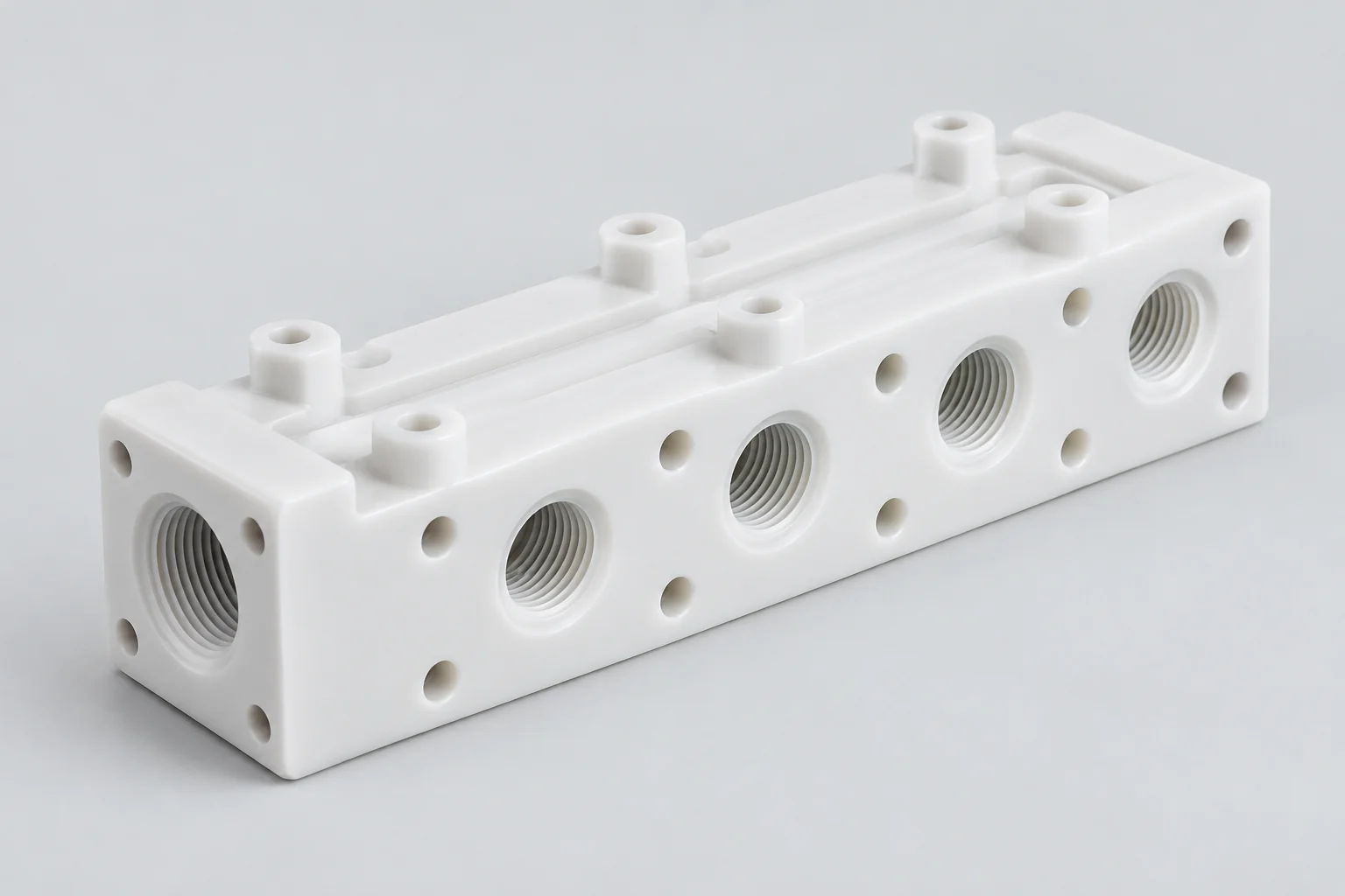
Cooling, pneumatic-control, analytical and test-system blocks with specified media compatibility and port interfaces.
Explore component details →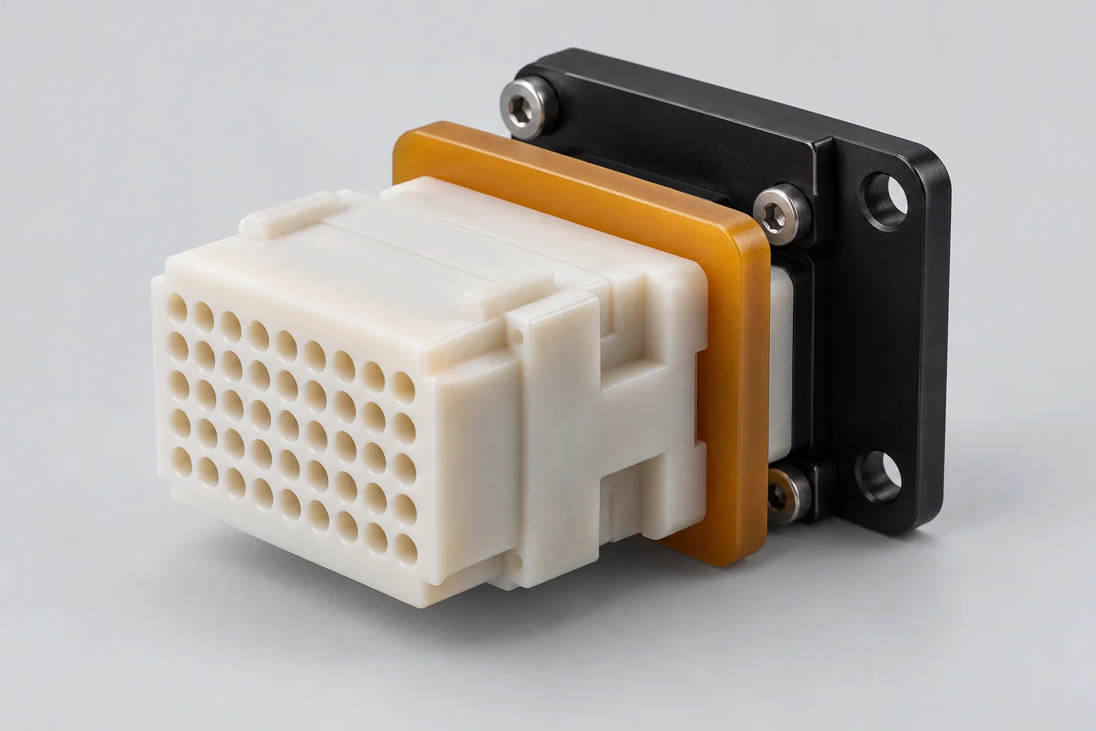
Drawing-based connector inserts, barriers, mounting plates and nonstandard electronic components.
Explore component details →Application, component and requirement belong together. A similar-looking block can serve a different electrical or mechanical function in each assembly.
Spacers, supports, standoffs, insulators, housings and fixture blocks maintain board position. Review insulation, heat exposure, dimensional stability and assembly fit.
Sensor housings, mounting blocks, optical supports and connector interfaces need accurate positioning, suitable insulation and resistance to the operating environment.
Connector housings, terminal supports, insulators and cable-routing parts combine close interface geometry with dielectric, temperature and creep requirements.
Busbar insulators, support blocks, spacers, barriers and housings require defined dielectric properties, creepage, clearance, temperature and any specified flame performance.
Fixtures, nests, insulating blocks, sensor mounts and enclosures locate devices without obscuring access for probes, connectors or inspection.
HMI and sensor housings, insulators, spacers and cable guides connect equipment structure to protected electronic interfaces. Include vibration, access and cleaning exposure.
There is no single best plastic. PEI is a candidate for heat-resistant insulating parts, PEEK for demanding structural and thermal applications, PPS for stable technical components and POM for moderate-temperature mechanical parts.
| Material | Main advantage | Typical electronics use |
|---|---|---|
| PEI / Ultem | Useful heat and electrical performance in suitable grades | Insulators, supports and housings |
| PEEK | Strength, temperature and chemical performance | Precision electrical and structural components |
| PPS | Dimensional and chemical stability | Technical insulating parts |
| POM / Delrin | Machinability and precision mechanical fit | Supports, fixtures and housings |
| PTFE | Dielectric and low-friction properties | Specialized insulation and sliding interfaces |
| Polycarbonate | Impact resistance and transparency | Enclosures, covers and windows |
| Acrylic / PMMA | Optical clarity | Display and sensor windows |
| PVC | Electrical and chemical properties | Electrical/process components |
Compare published data for the exact grade, stock form, thickness and test conditions. Filled grades may change electrical behavior as well as stiffness and machining response. Material family names alone do not establish flame rating, ESD suitability or compliance.
Insulators, spacers, standoffs, terminal supports, busbar supports, connector inserts and barriers separate conductive features while carrying assembly loads.
Resistance to electrical breakdown under stated test conditions. Thickness, temperature, moisture and geometry influence the finished insulation system.
Resistance through the bulk material. Review the supplier test method and conditions rather than treating a general polymer name as a specification.
Resistance along the surface. Contamination, humidity, finish and handling can influence surface behavior.
Relevant to selected electronic and RF applications. Match frequency and temperature conditions to the intended use.
Resistance to developing conductive surface paths under defined conditions. High-voltage or contaminated environments need the applicable material data.
Many engineering plastics are useful electrical insulators, but performance depends on exact grade, thickness, environment and test method. Select electrical properties together with mechanical load, retained fastener pressure and required spacing. Machining to dimensions does not establish dielectric certification of an assembly.
PCB spacers, board supports, connector housings, sensor bodies, cable guides, locating blocks, test fixtures and mounting plates bring multiple interfaces into a small volume.
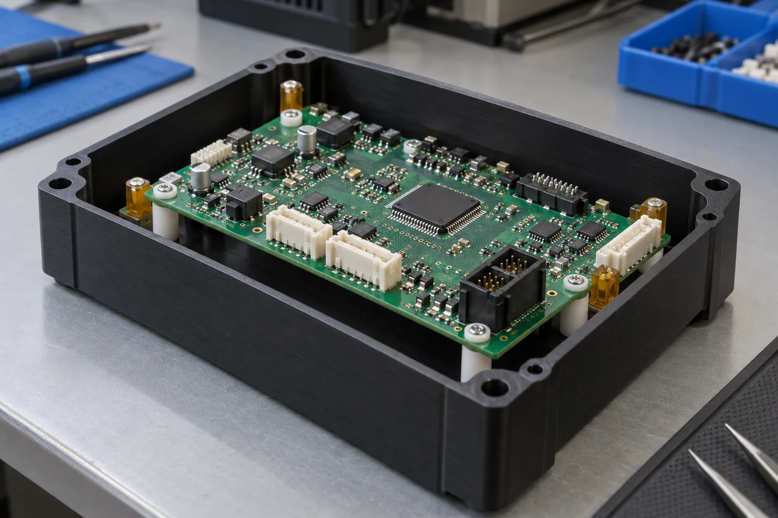
Locate connector openings and pin-support features from functional datums. Define mating geometry, allowed misalignment and insertion direction.
Control spacer height, support flatness and mounting positions so boards clear adjacent components without distortion.
Specify insert type, installation method, pull-out or torque criteria where required and adequate surrounding wall section.
Provide routing clearance and smooth contact surfaces. Include connector strain relief and access for installation or replacement.
Include localized heat sources and assembly processes. The housing temperature can differ from the board or connector hot spot.
Preserve room for tools, probes, fasteners and board insertion. Confirm the order of assembly before finalizing pockets and bosses.
For PCB and connector components, hole position, spacing, dielectric separation and interface geometry often matter more than overall outside dimensions. Provide the board outline or mating-part CAD with the component drawing to make these relationships reviewable.
Controllers, power supplies, sensors, communication devices, industrial instruments and test systems need more than an external box shape.
Define PCB envelope, component heights, mounting bosses, inserts and cable routes. Avoid loading the board through uneven supports.
Dimension connector cutouts, display openings, cable entries and mounting points to functional references. Identify visible or optical surfaces.
Specify heat paths, ventilation, sealing faces and gasket details. Enclosure geometry alone does not establish an IP rating or EMI shielding.
Release the insert and fastener BOM, access requirements and mating-cover fit. Agree installation and inspection scope before quotation.
CNC machining supports drawing-based housings without mold tooling. Wall thickness, deep pockets and mounting features still need material-aware review, especially when an enclosure combines delicate connector interfaces with sustained fastener loads.
Electronic equipment produces localized heat around power devices, processors, connectors and enclosed assemblies. Review continuous operating temperature, hot spots and short-term assembly exposure.
Stiffness changes as temperature rises. Evaluate the grade under the actual support and load rather than comparing an unloaded temperature value alone.
Plastic and metal hardware can expand differently. Allow for alignment changes, board spacing and retained fits across the operating range.
Fastener and insert loads may relax over time, particularly with heat. Review bearing area, preload and sustained stress.
Most standard plastics conduct heat poorly compared with metals. Heat sinks, ventilation, conductive paths or metal inserts may still be required.
A heat-resistant housing does not automatically solve thermal management. Supply hot-spot temperatures, duty cycle, nearby components and the cooling approach so material selection and fit can be assessed as a system.
Standard engineering plastics are typically insulating, not automatically ESD-safe. Static-dissipative or conductive behavior requires a specifically formulated and documented grade.
High resistance can provide electrical separation while allowing static charge to accumulate. Insulation and charge dissipation are different objectives.
A formulated grade allows controlled charge dissipation under specified conditions. Confirm resistance range, conditioning, test method and grounding arrangement.
Conductive fillers lower resistance. That behavior may conflict with electrical isolation, so review the entire assembly and intended current paths.
Electronics assembly fixtures, PCB handling tooling, semiconductor-related equipment, test nests and sensor tooling may require controlled static behavior. Black color is not evidence of an ESD grade. Supply a material designation, resistance requirements and verification scope; availability and suitability need confirmation before order.
Clearance is the shortest distance through air between conductive parts. Creepage is the shortest path along an insulating surface. Both affect electrical isolation in power electronics and high-voltage assemblies.
Shortest path through air
Shortest path along an insulating surface
Identify working voltage, transient voltage, insulation function and the governing equipment standard.
Pollution degree, material group, altitude and environmental exposure influence the applicable requirements.
Ribs, barriers and slots may change the surface or air path. Evaluate the actual assembled conductor geometry and applicable measurement rules.
There is no universal minimum distance for every plastic part. The responsible electrical design must set required distances under the applicable standard; TOPS can review machining and inspect specified geometry. Component dimensions do not replace system-level insulation testing.
Housings and insulators often combine thin walls, small features, tight interfaces and thermally sensitive materials in a single component.
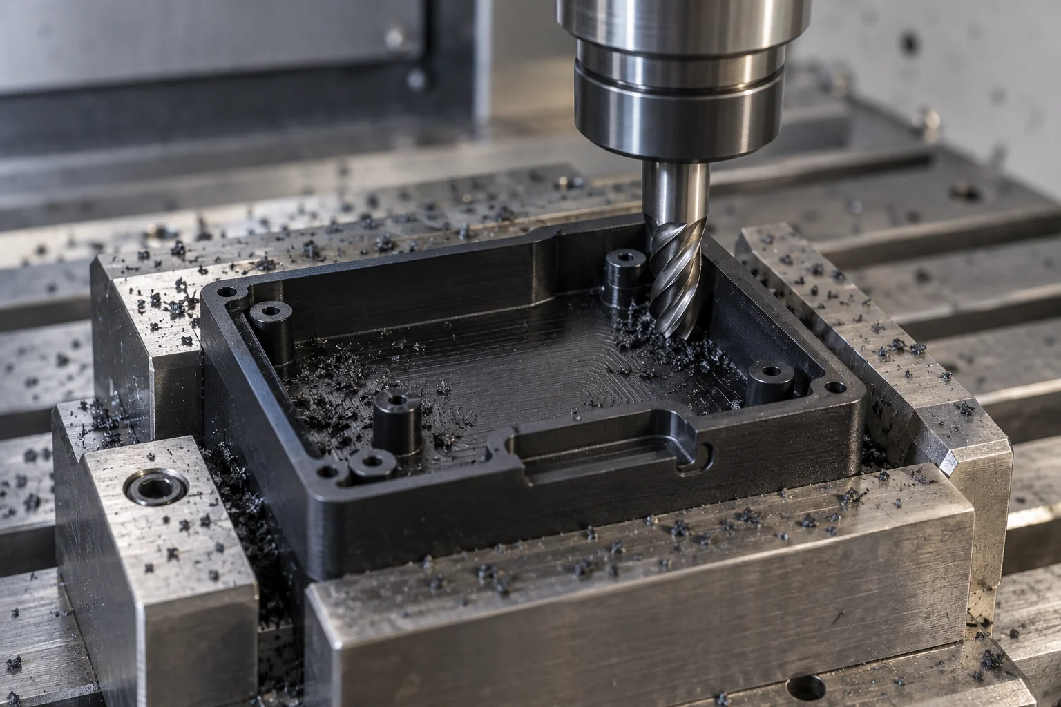
Clamping and cutting forces can deform slender sections. Use suitable support and plan inspection in the agreed free or restrained state.
Long tool reach and stock removal can affect finish and shape. Review corner radii, pocket depth and access.
Connector and PCB interfaces may need fine slots, hole patterns and narrow barriers. Confirm tool access and practical feature sizes.
Temperature changes affect plastic-to-metal fits and measurement. Define the relevant inspection and operating conditions.
Interference can distort thin housings or overload a boss. Review grade, section, insertion method and retained load.
Glass- and carbon-filled grades differ from unfilled polymers in tool wear, finish and electrical behavior. Use the exact compound specification.
Small burrs around connector openings, holes or insulating features can obstruct assembly or reduce functional clearance. Treat these surfaces as engineered features.
Remove interfering burrs while retaining required edges and dimensional features. Identify inaccessible areas on the drawing.
Provide clean threaded holes and seating faces. Define thread inspection and installed hardware requirements where relevant.
Specify optical or cosmetic acceptance separately. Machined transparency is not automatically an optical finish.
Control sealing or seating faces and remove sharp edges that could damage cables. Agree edge breaks and handling requirements.
Specify surface finish, allowable tool marks, cleanliness and edge conditions for the functional areas. Polishing or special cleaning requires an agreed scope; visual inspection alone does not establish electrical or optical performance.
Prioritize board position, connector alignment, insulation spacing and assembly interfaces. Agree realistic limits for the grade, geometry and inspection conditions.
| Feature | Why it matters |
|---|---|
| Hole position | PCB and connector alignment |
| Spacer height | Board spacing and mechanical stack |
| Housing cavity | Component fit and installation clearance |
| Connector opening | Mating-interface accuracy |
| Flatness | Assembly stability |
| Boss location | PCB mounting and supported position |
| Thread / insert position | Hardware fit and tool access |
| Insulation thickness | Electrical separation to the released design |
| Datum relationship | Alignment across multiple components |
Apply GD&T to the functional relationship rather than tightening every dimension equally. Include operating and inspection temperature, any conditioning, mating hardware and free-state requirements. Finished electrical performance remains a separate acceptance scope from dimensional inspection.
Agree the documents, acceptance features and traceability scope during quotation. Requirements depend on the exact grade and finished component.

Request supplier grade identification and certification where specified and available. Link the document to the actual supplied stock.
Check drawing-defined critical dimensions, insulation features and mating interfaces using an agreed method.
Define the first-article report scope, sample quantity and approval step before repeat production where required.
Maintain the released drawing, hardware BOM and approved changes for recurring OEM orders.
Confirm the required linkage between supplier stock, machining lot and delivery records before committing to a traceability scope.
Specify surface protection, handling and any verified static-control packaging requirements for shipment.
Material datasheets, flame-rating evidence, ESD data and RoHS/REACH information can be reviewed where supported by the exact material and process. No blanket UL94 V-0, UL listing, ESD-safe, EMI-shielded, high-voltage certified, IP65/IP67, flameproof, arc-resistant or dielectric-tested claim applies to all parts. Customer-specified electrical, flame, ESD, RoHS/REACH, material and inspection requirements can be reviewed during quotation.
Use each stage to close a different engineering question, then release the material and acceptance criteria for supply.
Validate form, fit, board layout, connector access and initial material choice with representative mating components.
Refine tolerances, electrical spacing and thermal behavior. Complete customer-required functional or electrical testing.
Supply industrial electronics and instrumentation builds to released CAD and agreed inspection requirements.
Maintain the exact material grade, released drawing, CNC program, inspection criteria and hardware BOM. Record approved changes.
Review the complete electrical and mechanical environment together: voltage, spacing, temperature, dimensional stability, static behavior, load and assembly interfaces.
Review PEI, PEEK, PPS, POM, PTFE, PC and other specified polymers against the application.
Connect insulators, spacers, housings and connector-related parts to their functional requirements.
Manufacture fine features, cavities, interfaces and multi-face parts from released drawings.
Review thermal expansion, wall thickness, support and inserts before machining.
Support electronics OEMs and equipment builders through development and recurring orders.
Agree critical interface checks, reporting and acceptance requirements for the defined component scope.
Move from application requirements to the detailed product page for geometry, interfaces and drawing preparation.
Direct answers about electrical insulation, thermal requirements, ESD, spacing, housings and recurring supply.
PEI, PEEK, PPS, POM, PTFE, PC, PMMA and PVC are candidates for different functions. Select the exact grade for electrical, thermal, mechanical and documentation requirements.
There is no universal best grade. Compare dielectric strength, resistivity, tracking resistance, thickness, temperature and environment alongside the applicable equipment requirements.
PEI can be a useful candidate for heat-resistant insulating supports and housings. Electrical and flame properties must be confirmed for the exact grade and application.
Consider PEEK when structural, thermal or chemical demands justify it. Check the grade, sustained loads, fit and required electrical properties before selection.
No. Standard engineering plastics are generally insulating. Static-dissipative or conductive behavior requires a documented formulated grade and appropriate system design.
Clearance is the shortest path through air; creepage is the shortest path along an insulating surface. Required distances depend on the applicable standard, voltage, environment, material and geometry.
Yes, specified inserts can be reviewed for installation. Define insert type, location, surrounding wall section, assembly method and retention requirements.
Board spacing, hole position, connector alignment, insulation features and assembly datums are usually priorities. Specify the critical relationships and inspection state.
Yes, drawing-based connector and sensor housings can be reviewed for CNC machining. Supply mating geometry, material, electrical conditions and critical interfaces.
Yes, prototype, low-volume and recurring supply can be reviewed. Release the material grade, CAD revision, hardware BOM, quantity and acceptance requirements.
VOLTAGE. GRADE. SPACING. INTERFACE.
Upload your electronics component drawing or CAD model and specify the exact material grade, quantity, operating voltage, temperature, ESD requirement, critical dimensions, inserts, assembly interfaces and documentation needs. TOPS Plastics can review the geometry and machining feasibility before quotation.
Company, name, email and phone are required. Country, part number, quantity and drawing upload are optional. Include technical requirements in the drawing or email; combine CAD and supporting files into one ZIP if useful.
info@tops-precision.comSTEP / STP / IGES / X_T / DWG / DXF / PDF or ZIP, maximum 10 MB. Larger packages can be shared by email. Agree confidential-file handling before sending sensitive drawings.