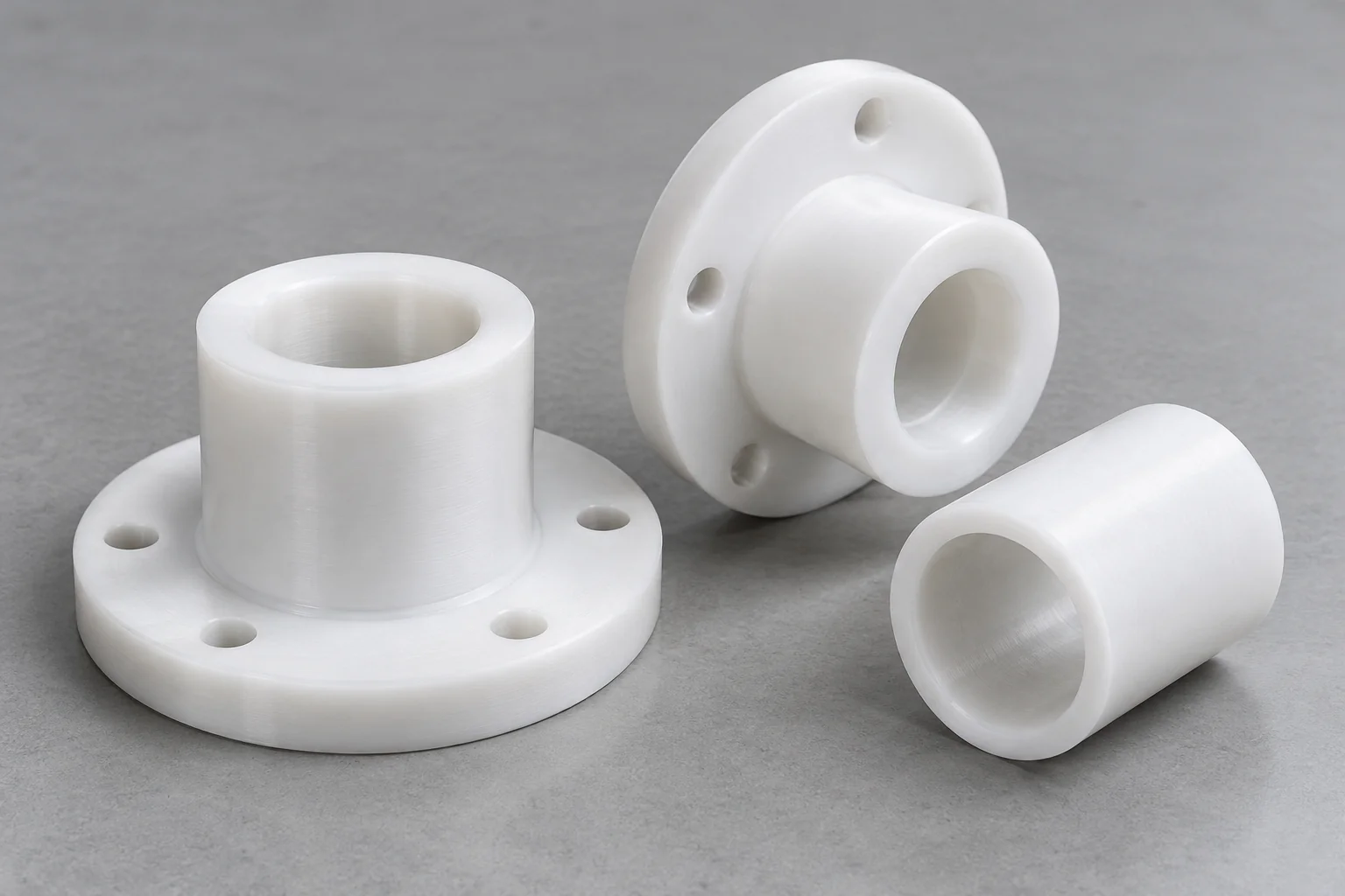
Plastic Bushings
Custom sleeves and flanged bushings with specified OD, ID and bearing interfaces. Define the mating shaft, clearance and operating conditions so the fit can be reviewed.
Explore manufacturing guidance →
CUSTOM COMPONENTS / ENGINEERING PLASTICS
TOPS Plastics manufactures custom CNC machined plastic parts for industrial equipment, automation, semiconductor, medical equipment and other OEM applications. From bushings and gears to complex manifolds, housings and mechanical components, we produce parts from engineering plastics according to your drawings and CAD models.
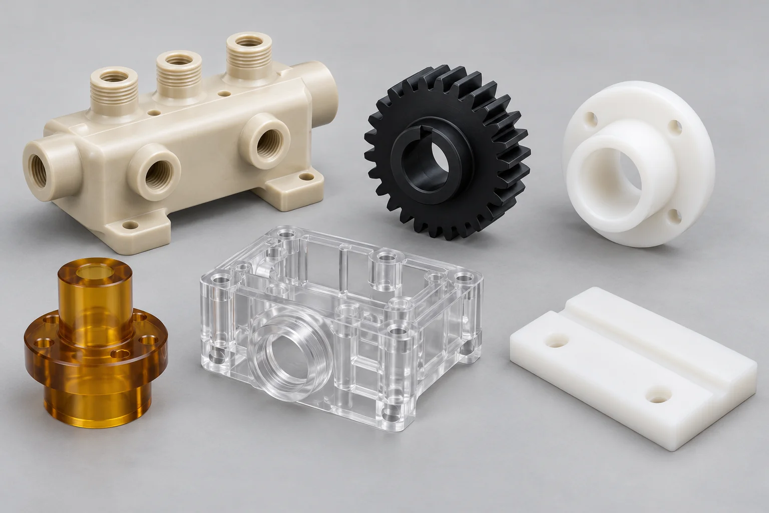
Custom components from engineering plastics, with the manufacturing route and inspection plan reviewed against your drawing.
| Capability | Project scope |
|---|---|
| Manufacturing processes | CNC milling, turning, drilling, tapping and multi-axis machining where the geometry requires it. |
| Components | Bushings, gears, rollers, bearings, spacers, insulators, manifolds, housings and fabricated components. |
| Materials | Engineering and high-performance polymer families in specified stock grades. |
| Customization | Geometry, dimensions, grade, available stock color, surface requirements and quantity. |
| Production | Functional prototypes, low-volume batches and repeat OEM orders. |
| Input documents | 3D CAD, dimensioned 2D drawings and reference sample information. |
| Inspection | Drawing-based dimensional checks and agreed reporting requirements. |
| Tolerances | Reviewed by material, geometry, feature and inspection conditions. |
| Secondary services | Applicable polishing, bonding and assembly, subject to project review. |
Explore component configurations, then send your drawing for a part-specific review.
Custom sleeves and flanged bushings with specified OD, ID and bearing interfaces. Define the mating shaft, clearance and operating conditions so the fit can be reviewed.
Explore manufacturing guidance →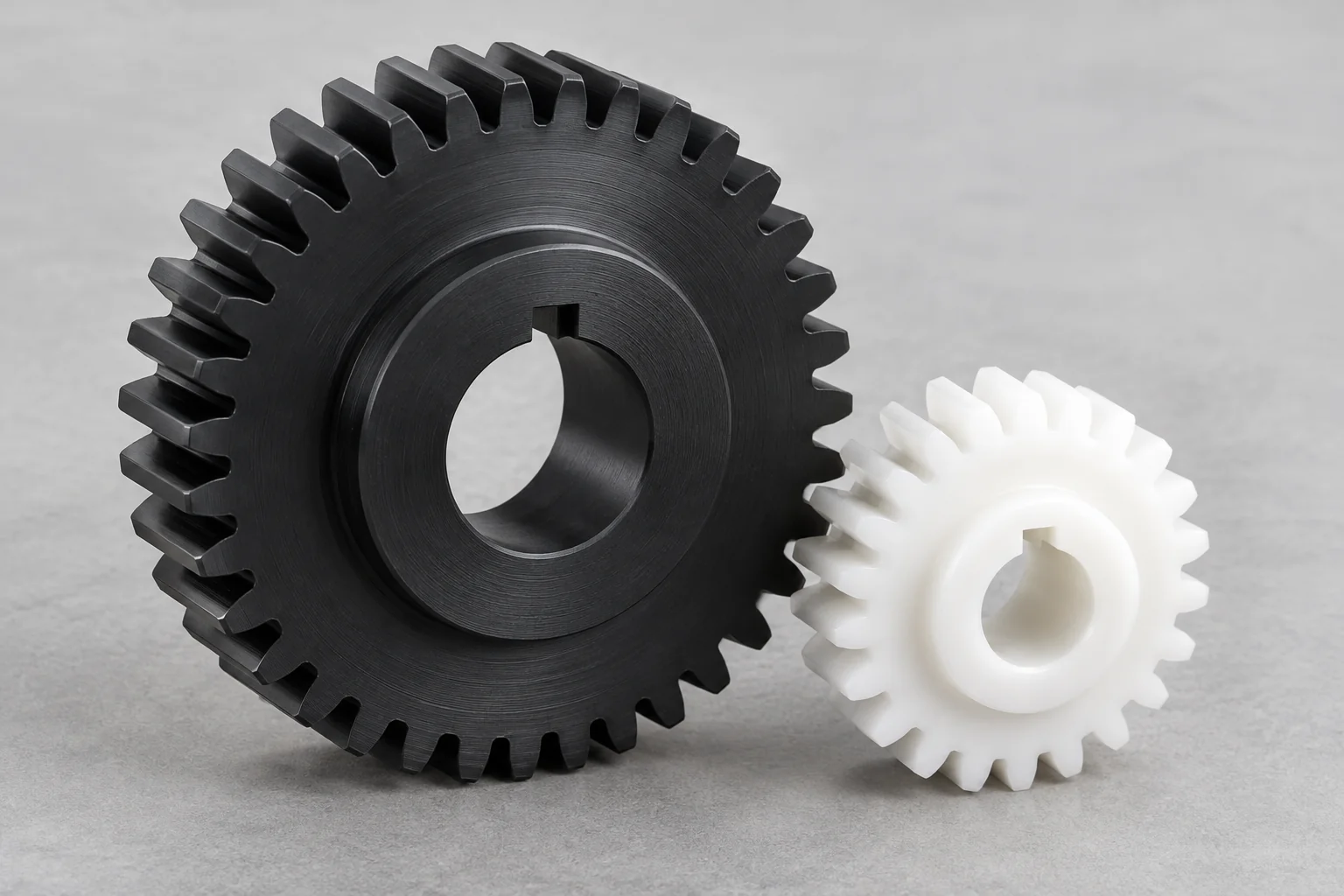
Machined gears with defined tooth geometry, bores and keyways. Provide the gear specification, mating geometry, torque and operating environment for review.
Explore manufacturing guidance →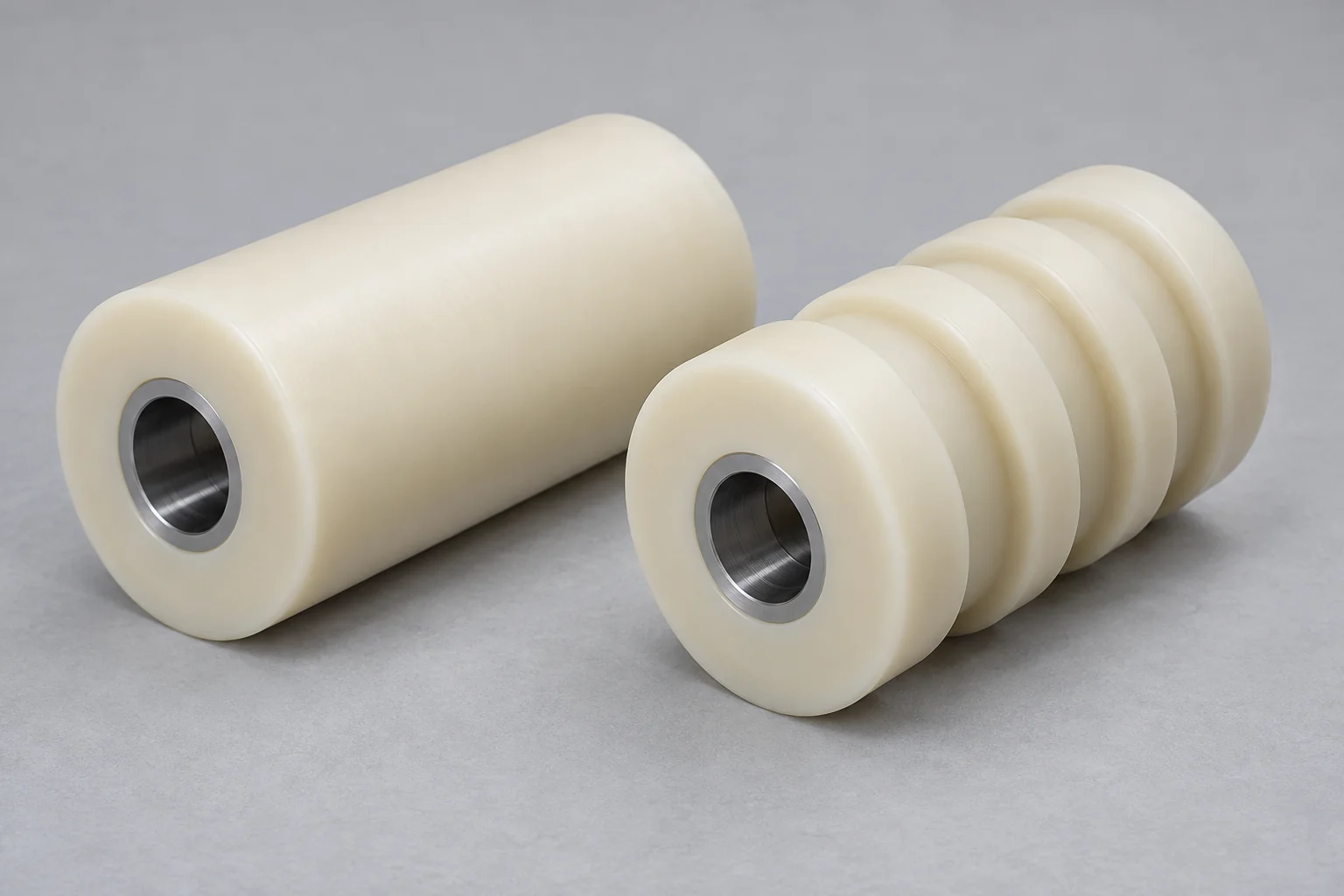
Custom rollers for conveying, packaging and automation equipment. Specify the profile, shaft interface, loading and required surface condition.
Explore manufacturing guidance →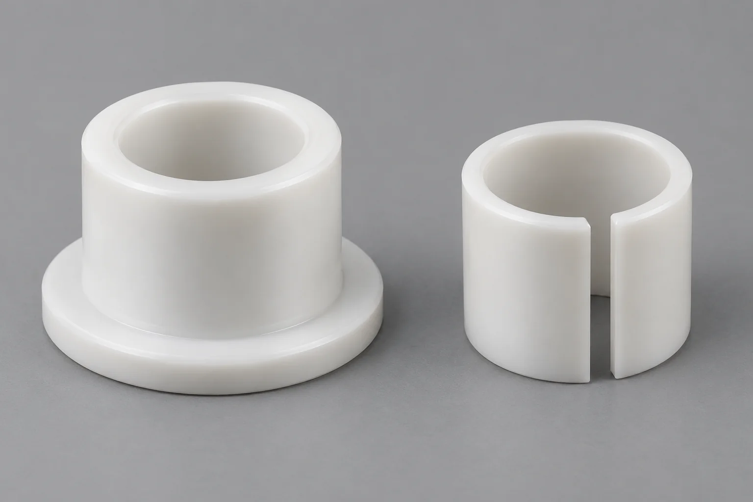
Plain bearing and sliding components made to the required geometry. Material choice and clearance depend on load, speed, temperature and lubrication conditions.
Explore manufacturing guidance →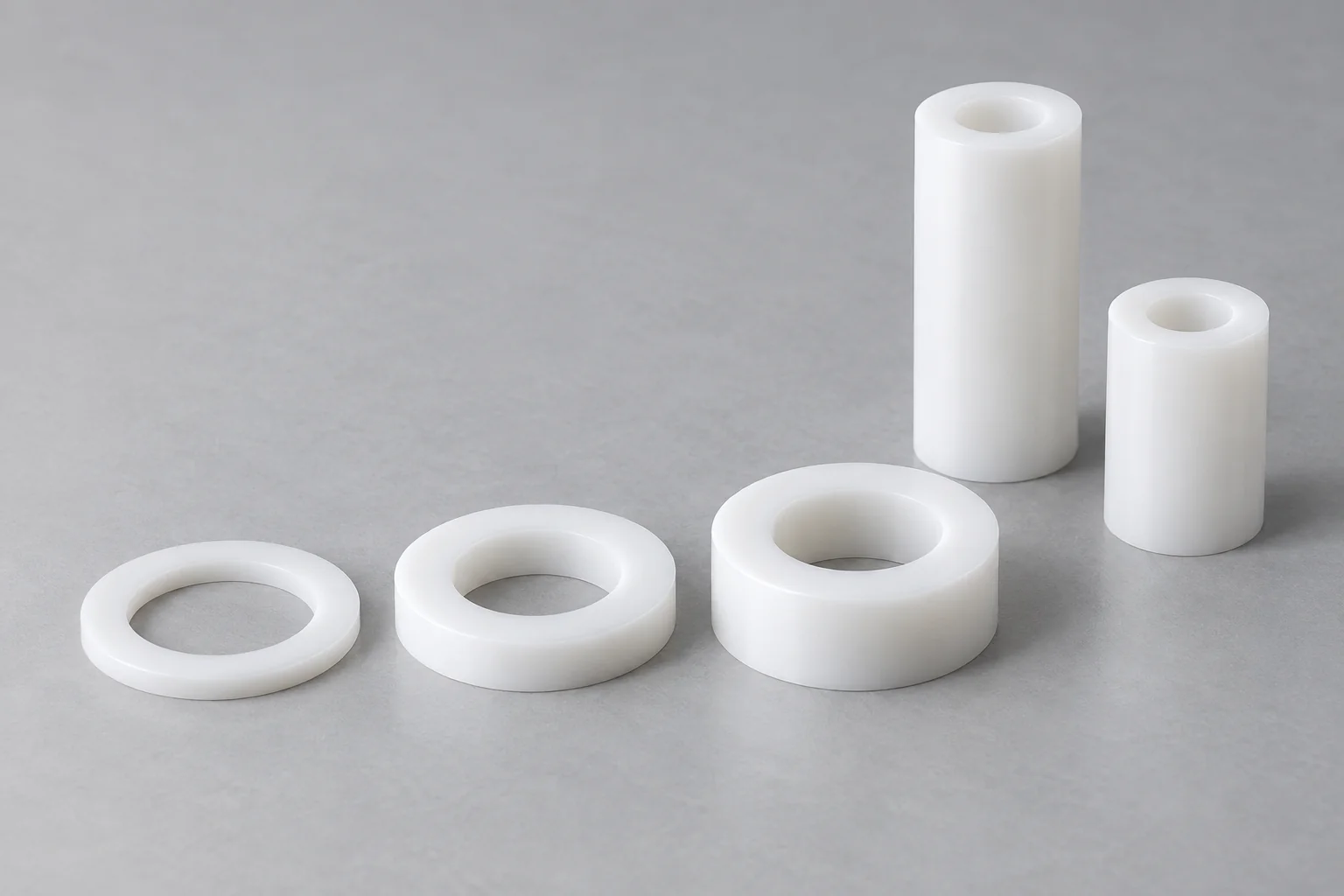
Precision rings, standoffs and alignment components with custom thickness and diameters. Identify the contact faces and dimensions that establish the assembled position.
Explore manufacturing guidance →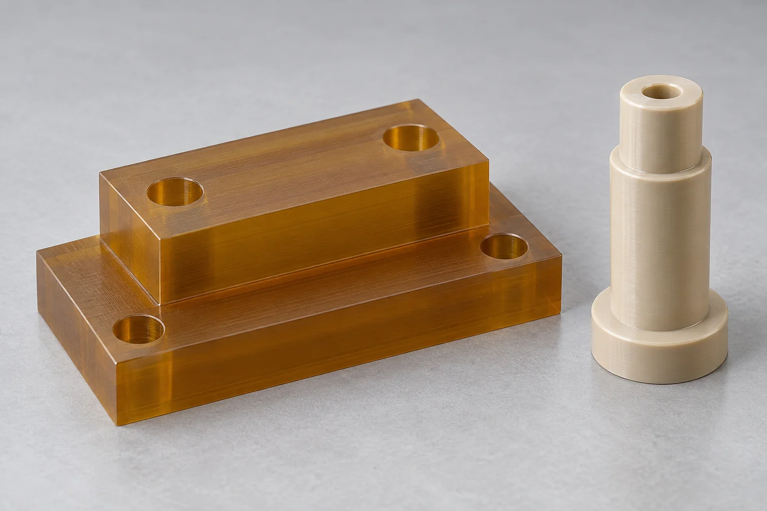
Machined insulating blocks, supports and standoffs for equipment assemblies. Specify electrical, thermal and mechanical requirements for the actual grade.
Explore manufacturing guidance →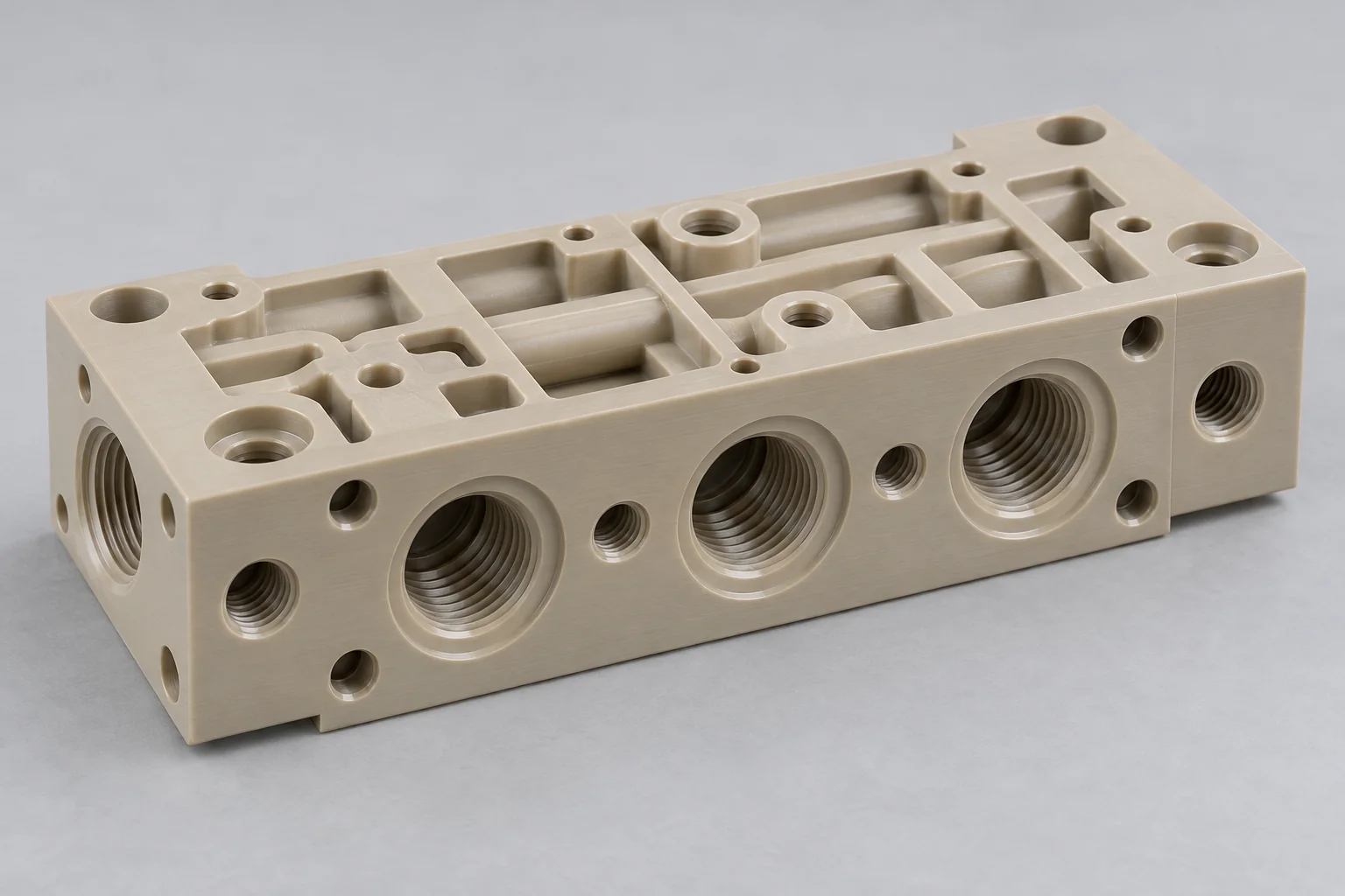
Custom blocks with flow passages, ports and sealing interfaces. Provide media, pressure, thread and cleanliness requirements before the manufacturing route is selected.
Explore manufacturing guidance →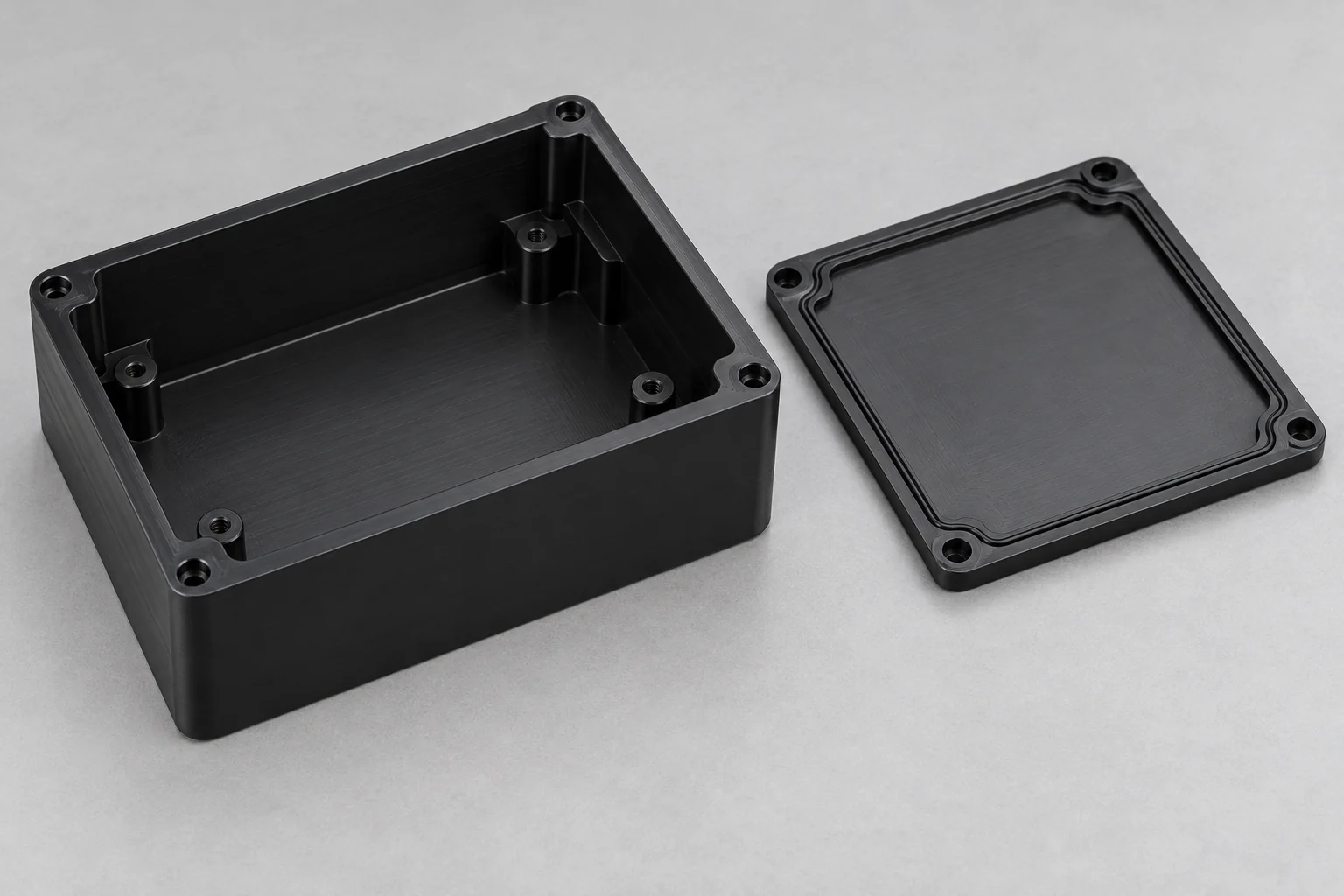
Custom instrument and equipment enclosures with covers and mounting features. Define access, hardware, finish and any assembly requirements.
Explore manufacturing guidance →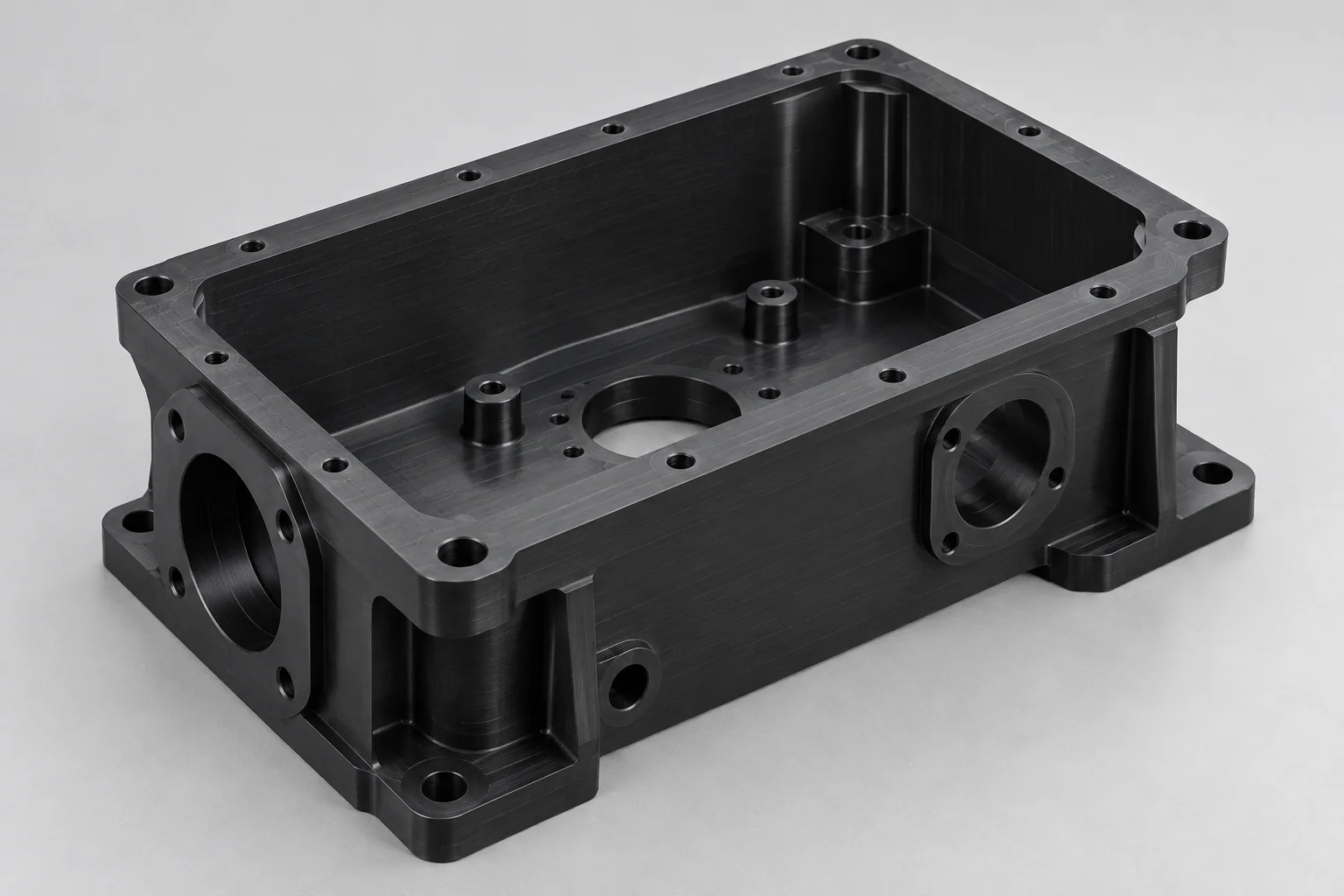
Machined structural housings with cavities, side bores and locating features. Relate critical dimensions to the mating components and assembly datums.
Explore manufacturing guidance →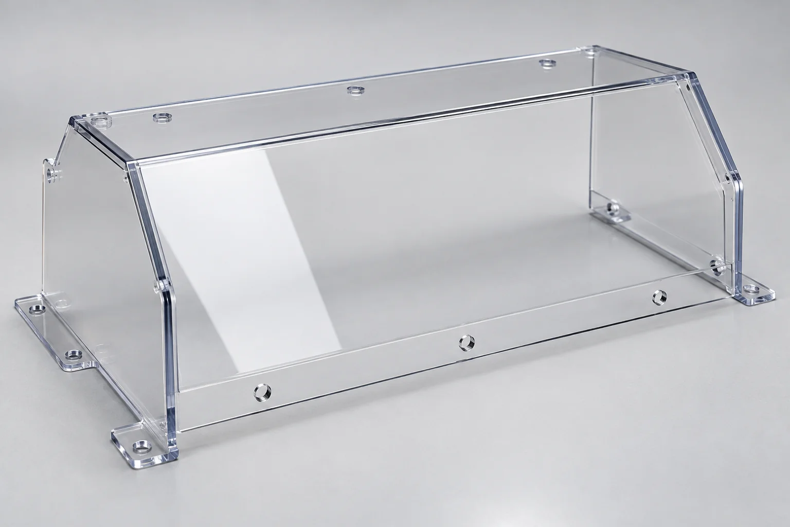
Protective panels and covers from suitable transparent or opaque polymers. Material and geometry must be reviewed against the equipment risk assessment and applicable requirements.
Explore manufacturing guidance →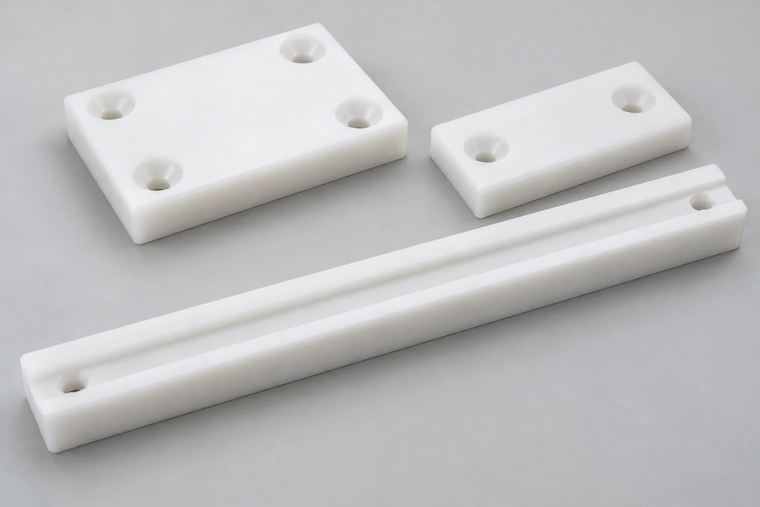
Replaceable pads, guide strips and sliding surfaces for machinery. Specify wear conditions, mating surfaces, mounting geometry and expected loading.
Explore manufacturing guidance →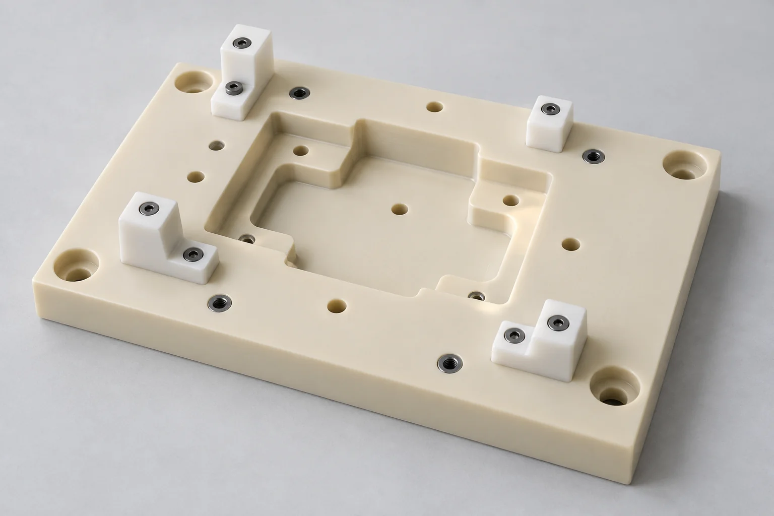
Custom locating plates, assembly tooling and inspection supports. Define datum features, clamping access and the workpiece interfaces.
Explore manufacturing guidance →Your component is defined by its function and drawing, rather than a fixed catalog size.
Custom machined plastic parts are produced to customer-specific geometry, dimensions, material grades and functional requirements. TOPS Plastics reviews the drawing and application before selecting stock, machining and inspection approaches.
| Parameter | Customization for review |
|---|---|
| Material | Polymer family, exact grade and reinforcement. |
| Geometry | Customer-specific shapes from CAD and drawings. |
| Dimensions | OD, ID, length, width, height and thickness. |
| Features | Holes, slots, pockets, grooves and threads. |
| Fits | Clearance, running, locating and specified mating interfaces. |
| Surface | As-machined, deburred or polished where suitable. |
| Color | Subject to the available specified stock grade. |
| Quantity | Prototype through recurring order quantities. |
| Inspection | Critical features, acceptance criteria and agreed reports. |
Material selection starts with the component duty: load, temperature, wear, chemicals, electrical requirements and inspection state.
Precision insulators, bushings and manifolds for demanding temperatures; select the grade for actual loads and exposure.
PEEK →Gears, rollers and spacers where machinability, low friction and dimensional stability are useful.
Delrin / POM →Seals, bushings and insulating components where chemical compatibility and low friction matter; account for creep.
PTFE →Rollers, guides and gears requiring toughness and wear performance; define moisture and inspection state.
Nylon →Wear pads and guides requiring abrasion and impact resistance; review stiffness and retained geometry.
UHMW →Guards, covers and windows requiring transparency and impact resistance; review stress and chemical exposure.
Polycarbonate →Transparent blocks and covers for viewing and cosmetic requirements; protect edges and manage local stress.
Acrylic / PMMA →Insulators and higher-temperature equipment components; electrical and thermal suitability depends on grade.
Ultem / PEI →Specify the exact stock grade and documentation required. A polymer family name alone does not establish compliance or suitability for an assembled product. Explore the material pages for detailed grade and machining considerations.
Explore All Engineering Plastic Materials →The component geometry determines the process. Detailed machining guidance is available on the individual service pages.
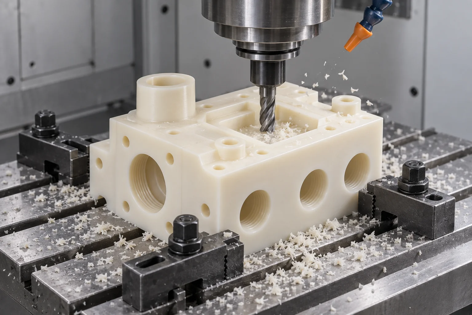
For housings, manifolds, fixture plates, pockets and features on multiple faces. Review internal radii, tool access and the relationship between setups.
Explore the process →For bushings, sleeves, spacers, rollers, rings and other rotational parts. Bore geometry, concentric relationships and released dimensions guide the setup.
Explore the process →For complex surfaces, compound angles and multi-face access where the geometry justifies it. The process does not remove the need to control workholding and inspection datums.
Explore the process →Achievable tolerance depends on polymer, grade, size, wall thickness, workholding, machining sequence and inspection conditions. Evaluate critical fits individually instead of applying one universal tolerance to all plastics.
| Requirement | Main consideration |
|---|---|
| Critical bore | Material stiffness, bore geometry and measurement contact force. |
| Flatness | Stock stress, section thickness and machining sequence. |
| Concentricity / runout | Setup and datum relationships. |
| Thin walls | Workholding and measurement deformation. |
| Nylon precision fits | Moisture conditioning and defined inspection state. |
| PTFE / UHMW | Creep, elasticity and support during measurement. |
| Large components | Thermal expansion and temperature uniformity. |
| Multi-face geometry | Datum control and an agreed measurement method. |
Mark functional features and their mating relationships on the drawing. Define the relevant temperature, conditioning, contact force and inspection method when these influence acceptance. Our tolerance review is specific to the component; no blanket numerical capability is implied.
Describe the purpose of each feature so machining and inspection focus on the assembled function.
Locate a shaft, guide a moving component or establish a mating fit. Specify the functional diameter and datum relationship.
Provide space for instruments, hardware or fluid paths. Review access, wall thickness and internal corner radii.
Guide movement, route components or provide controlled adjustment. Define width, position and the surfaces that contact the mating part.
Connect hardware or fittings. Specify the thread standard, engagement and any sealing requirement.
Locate gaskets, seals or retaining elements. Groove dimensions and surface condition must suit the selected mating component.
Seat fasteners or provide tool clearance. Review remaining section thickness and how fastening loads enter the polymer.
Match contours, direct movement or provide clearance. Define the reference geometry and how the profile will be checked.
Position pins, bushings or adjacent components. Review interference, insertion support and dimensional changes after assembly.
A clear functional drawing improves manufacturability and makes a quotation more useful.
Review temperature, loading, chemicals, wear, friction and electrical requirements before choosing the grade. Include the operating environment in the RFQ.
Identify the dimensions that govern fit or operation. Avoid unnecessary precision on noncritical surfaces, which can add machining and inspection work.
Rotating milling tools generally leave internal corner radii. Design accessible corners or discuss a suitable alternative when a mating component needs clearance.
Thin polymer sections can deflect during cutting, measurement and fastening. Review support, thickness transitions and stock removal.
Temperature affects dimensions, while moisture is especially relevant to nylon. Define the state in which precision fits must be accepted.
Specify mating parts, fastening loads, thread engagement and locating datums. Consider access, retained preload and replacement requirements.
Component examples for engineering review. Suitability and any industry-specific documentation must be agreed for the application.
PEEK locating fixtures, PVDF manifold blocks and precision insulating supports for equipment interfaces. Confirm grade, cleanliness and documentation requirements.
Explore industry applications →Instrument housings, mechanical components and equipment fixtures. Specify the intended use and applicable regulatory or cleaning requirements.
Explore industry applications →Gears, bushings, rollers and replaceable wear parts designed around load, movement and service access.
Explore industry applications →Guides, spacers, locating brackets and tooling components with defined datums and mating interfaces.
Explore industry applications →Insulating supports, instrument enclosures and testing fixtures. Define electrical properties and hardware requirements for the actual grade.
Explore industry applications →Manifolds, valve-related components and sealing parts. Review chemical compatibility, ports, surface conditions and any required tests.
Explore industry applications →Finished-part acceptance starts with the material and drawing. Agree the inspection scope, sampling and documentation before manufacture.
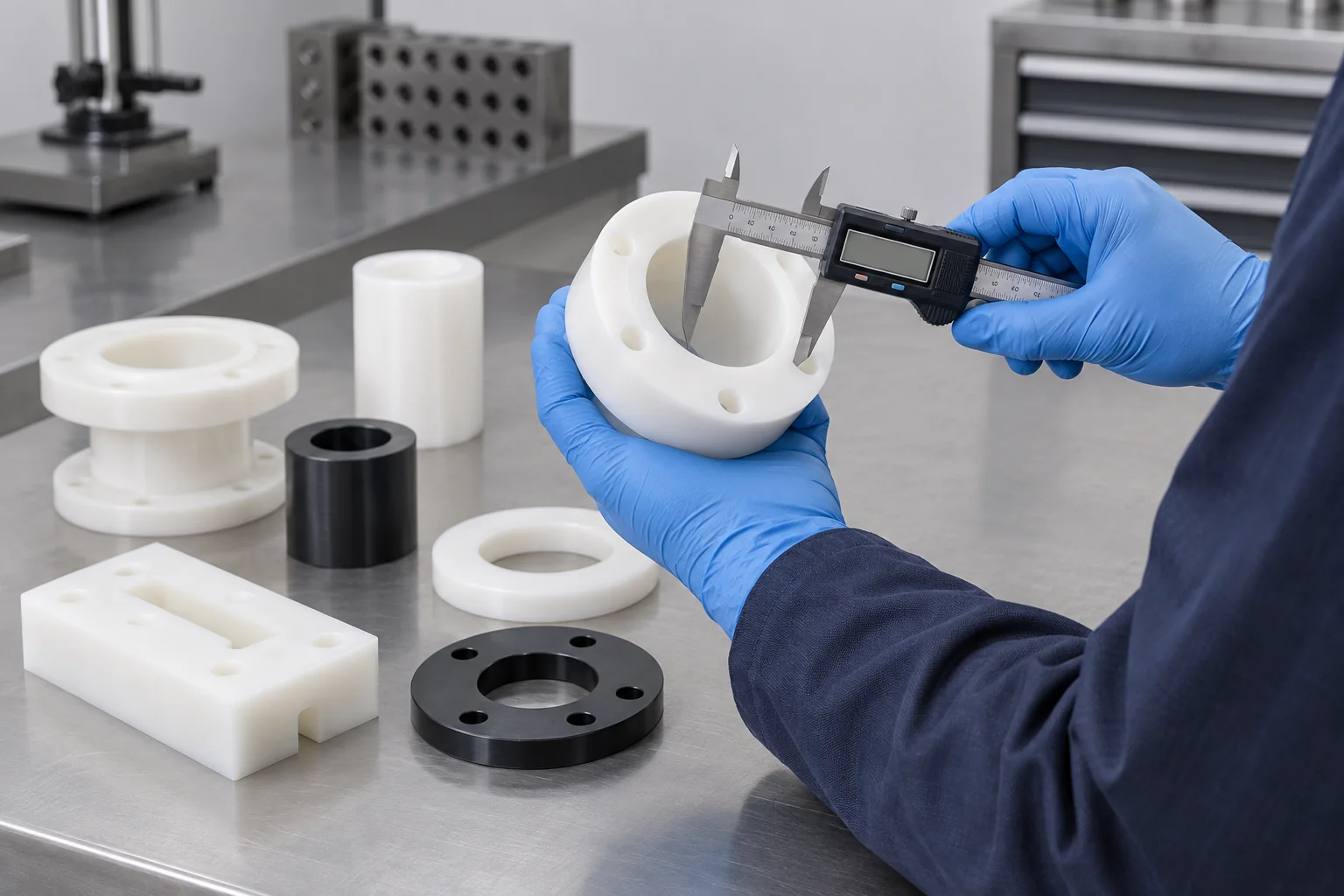
Material Grade Verification — identify the specified stock and required supplier records.
Drawing & Critical Dimension Review — confirm revision, datums and functional features.
First Article Inspection — agree whether a first article and approval record are required.
In-Process Dimensional Checks — check features while access and correction remain practical.
Final Part Inspection — verify agreed dimensions, surface condition and drawing requirements.
Cleaning & Protective Packaging — apply the specified handling and packing requirements.
Measurement equipment and methods must suit the polymer, feature size and contact sensitivity. Where a report is required, agree the characteristics, sampling and format; inspection documents or certifications are not assumed included in every order.
Use the same approved component definition as the project develops.
Custom functional parts support dimensional validation, assembly testing and design changes. Record changes before releasing the next revision.
Small batches can be machined from stock without dedicated molding tooling. Review setup work, material availability and the required quantity.
Controlled drawings, machining programs and specified inspection requirements support recurring orders. Review substitutions or revision changes before production.
A component-focused review connects the drawing to the material, process and acceptance requirements.
Review stiffness, moisture, creep, temperature and chemical exposure for the specified component duty.
Define custom geometry and functional interfaces using the approved CAD and drawing revision.
Choose the process around rotational features, cavities, tool access and multi-face relationships.
Identify the features that govern function and discuss practical radii, wall thickness and inspection.
Plan the route around the current stage and preserve the approved requirements for future batches.
Agree what must be measured, under which conditions and with which records.
Review applicable polishing, bonding and assembly together with the finished dimensions and interfaces.
Follow a drawing-controlled route from inquiry to protected delivery.
Upload CAD, an engineering drawing or sample information. Identify the part number and revision.
Confirm polymer grade, quantity, application and specifications. Include finish and documentation requirements.
Review manufacturability, tolerances and cost drivers. Resolve critical interfaces and acceptance conditions.
Select milling, turning or a combined process. Plan workholding and access around the geometry.
Manufacture the parts to the approved definition. Complete the specified feature and surface operations.
Perform critical dimensional and final inspection. Use the agreed method and reporting requirements.
Complete agreed finishing and protective packaging. Protect mating faces, transparent surfaces and edges.
They are components cut from polymer stock to customer-specific geometry, dimensions and requirements. The drawing and material specification define the part rather than a fixed catalog size.
PEEK, Delrin/POM, PTFE, Nylon, UHMW, polycarbonate, acrylic and Ultem/PEI are examples. The exact grade and component geometry determine suitability and machining considerations.
Yes, CAD and dimensioned drawings provide the basis for review. Include the revision, exact material grade, quantity and any critical fits or inspection requirements.
CNC machining removes material from stock; injection molding forms parts in dedicated tooling. Volume, geometry, material, design maturity and tooling economics determine the more suitable route.
Tolerances require component-specific review. Polymer behavior, size, geometry, workholding and inspection conditions prevent one numerical tolerance from applying to all parts.
There is no universal best material. POM, Nylon, PEEK and other grades may be considered based on load, speed, wear, temperature, lubrication and mating surfaces.
Yes, it can suit prototypes and small batches without dedicated molding tooling. Setup effort, stock availability and geometry still affect cost and delivery.
Yes, threads and insert interfaces can be reviewed with the component design. Specify the standard, engagement, installation method and required retention or fastening performance.
Send a 3D CAD model and dimensioned drawing where available, plus material, quantity and critical requirements. A PDF drawing and a ZIP containing CAD and supporting instructions can be uploaded through the inquiry form.
Repeat orders can be reviewed against controlled drawings, approved grades and inspection requirements. Identify the current revision and discuss any material or hardware substitutions before release.
YOUR DRAWING. YOUR COMPONENT.
Upload your CAD model or engineering drawing and specify the plastic material, quantity, critical dimensions, tolerances, surface finish and application. TOPS Plastics can review the manufacturing approach and quote against your custom component requirements.
Include annual demand, part dimensions, assembly requirements, critical tolerances and additional instructions in your drawing package or email. Company, name, email and phone are required; country, part number, quantity and drawing upload are optional.
info@tops-precision.comSTEP / STP / IGES / X_T / DWG / DXF / PDF or ZIP, maximum 10 MB. Larger packages can be shared by email. Agree confidential-file handling before sending sensitive drawings.