01
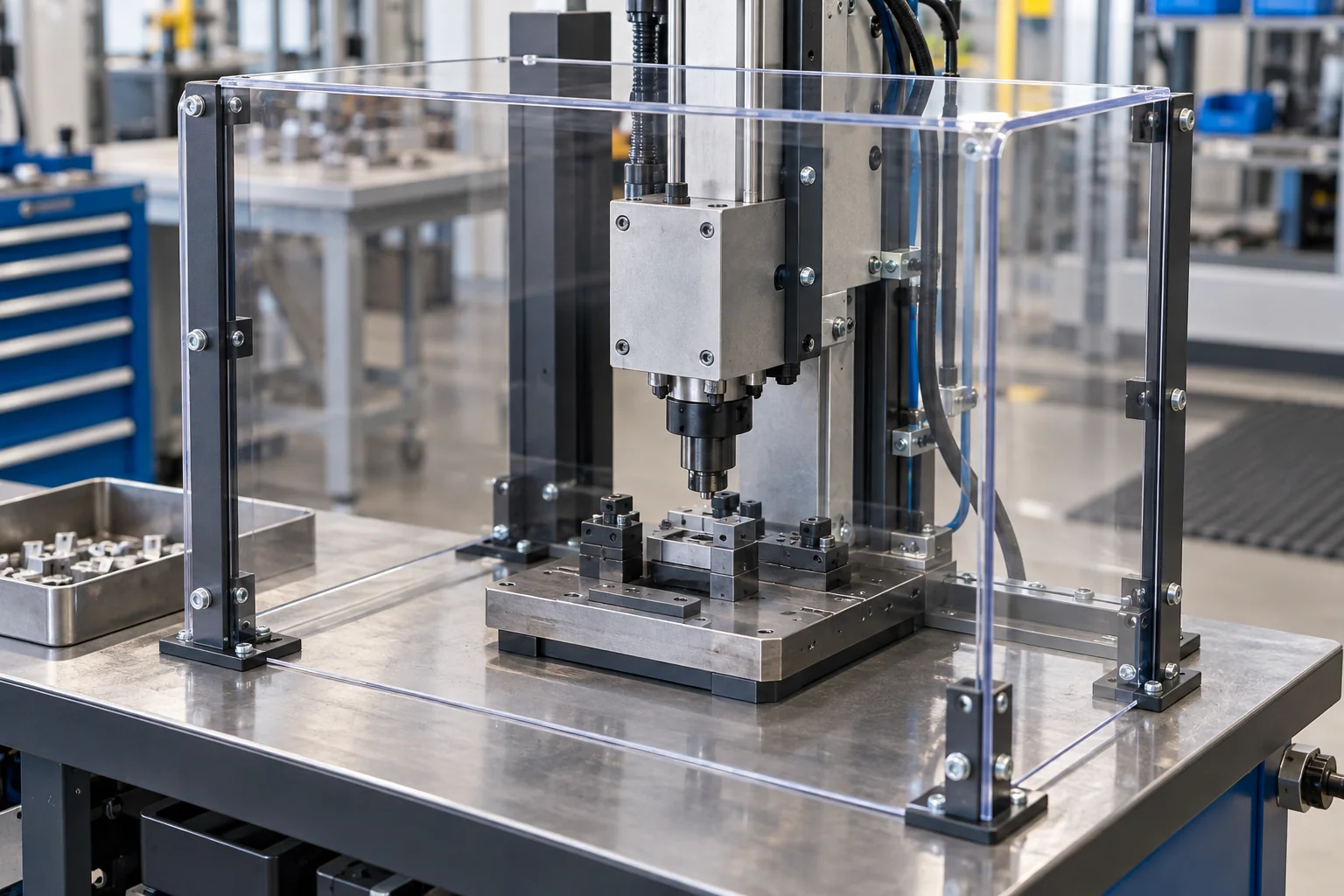
Point-of-Operation Guards
Barriers around the machine working area, with openings and distance from the hazard defined by the machine safety design. Specify loading, tooling and observation needs.
Discuss this guard →
CLEAR VIEW. CUSTOM FIT.
TOPS Plastics manufactures custom plastic machine guards, polycarbonate safety shields, protective covers and equipment panels for industrial machinery, automation systems and OEM equipment. We fabricate flat, bent and multi-feature guards with custom mounting holes, slots, cutouts, hinges and access features according to customer drawings and machine interfaces.
Bring the machine envelope, guard specification and mounting details. We review fabrication feasibility and the drawing-defined acceptance requirements before quotation.
| Feature | Project requirement |
|---|---|
| Guard types | Flat panels, bent guards, protective covers, safety shields and access panels |
| Primary material | Polycarbonate in the specified sheet grade |
| Other materials | Acrylic, ABS, HDPE, PVC and specified plastics where appropriate |
| Processes | CNC routing, drilling, cutting, bending and fabrication |
| Features | Mounting holes, slots, viewing areas, hinges, fasteners and specified labels |
| Supply format | Single panels, coordinated kits or agreed assemblies |
| Production | One-off replacement, low-volume and repeat OEM supply |
| Input | CAD, DXF, drawings, dimensioned sketches and physical samples |
| Inspection | Dimensions, hole position, bend geometry, surface condition and agreed fit checks |
Select a guard construction around the machine hazard, viewing needs and mounting arrangement. Each part follows the released drawing and approved specification.
Barriers around the machine working area, with openings and distance from the hazard defined by the machine safety design. Specify loading, tooling and observation needs.
Discuss this guard →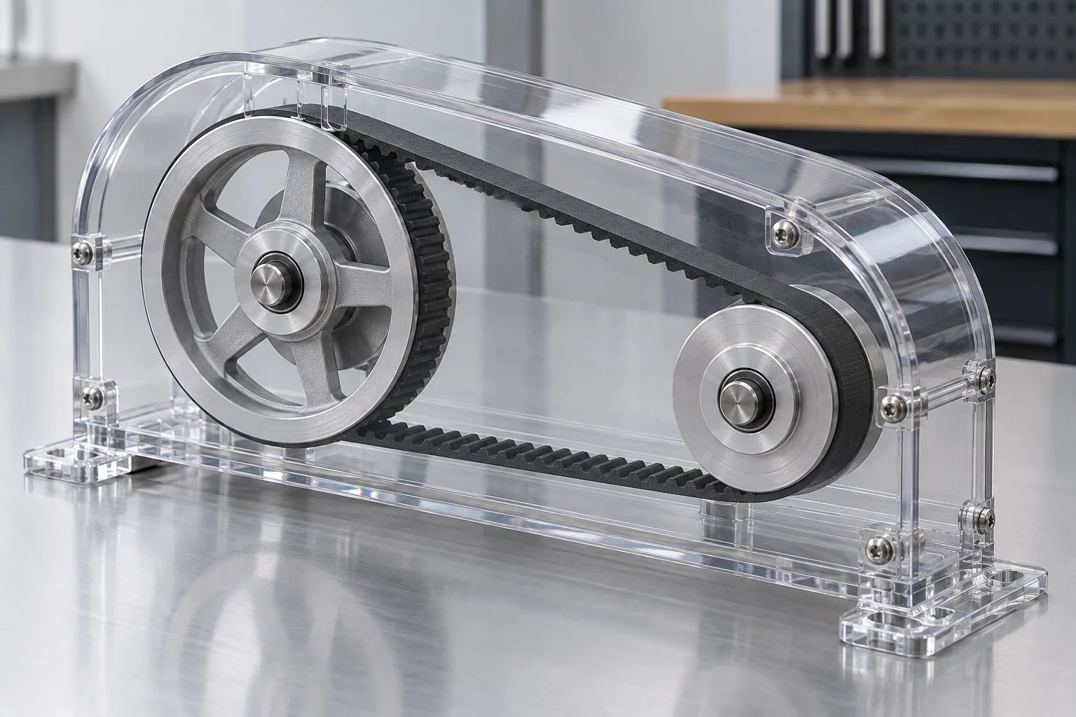
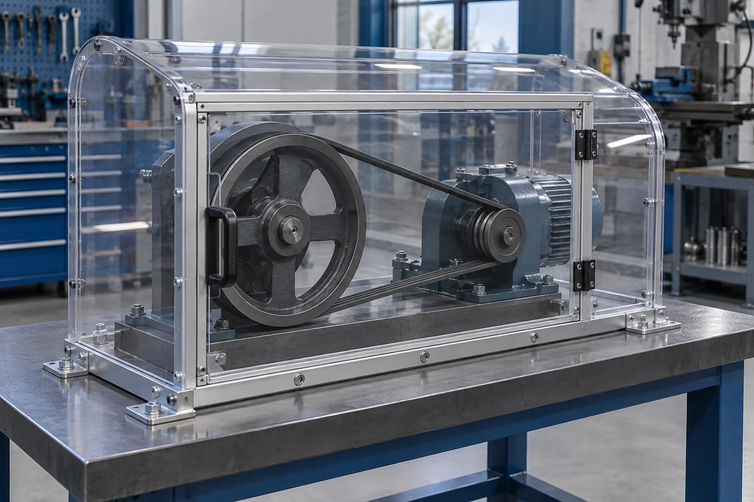
Custom covers for belts, pulleys, shafts, couplings and fans. Coordinate the complete enclosure, supporting frame, clearance and maintenance access.
Discuss this guard →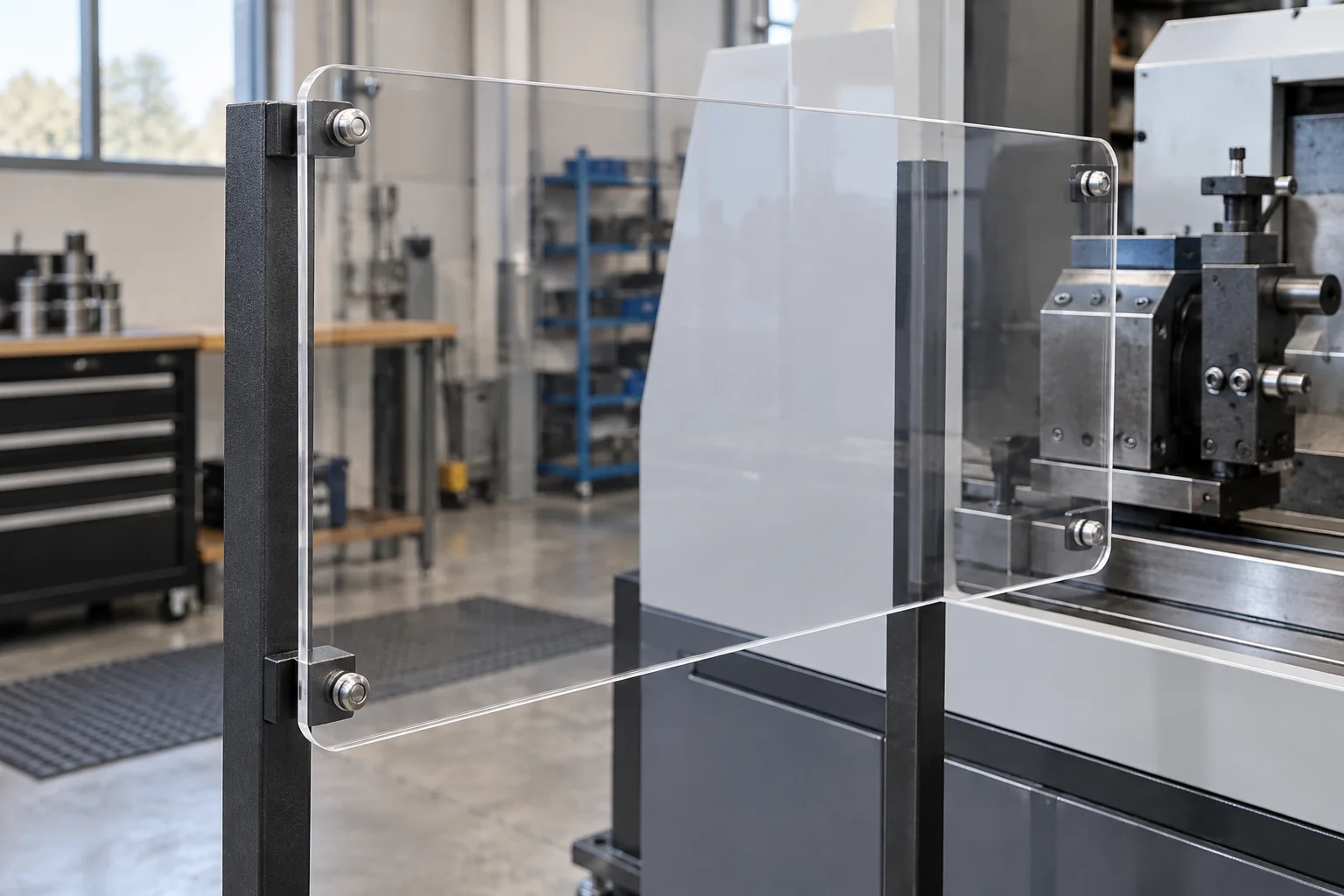
Clear process-viewing panels with drawing-defined profiles and mounting features. Distinguish splash shielding from engineered impact containment.
Discuss this guard →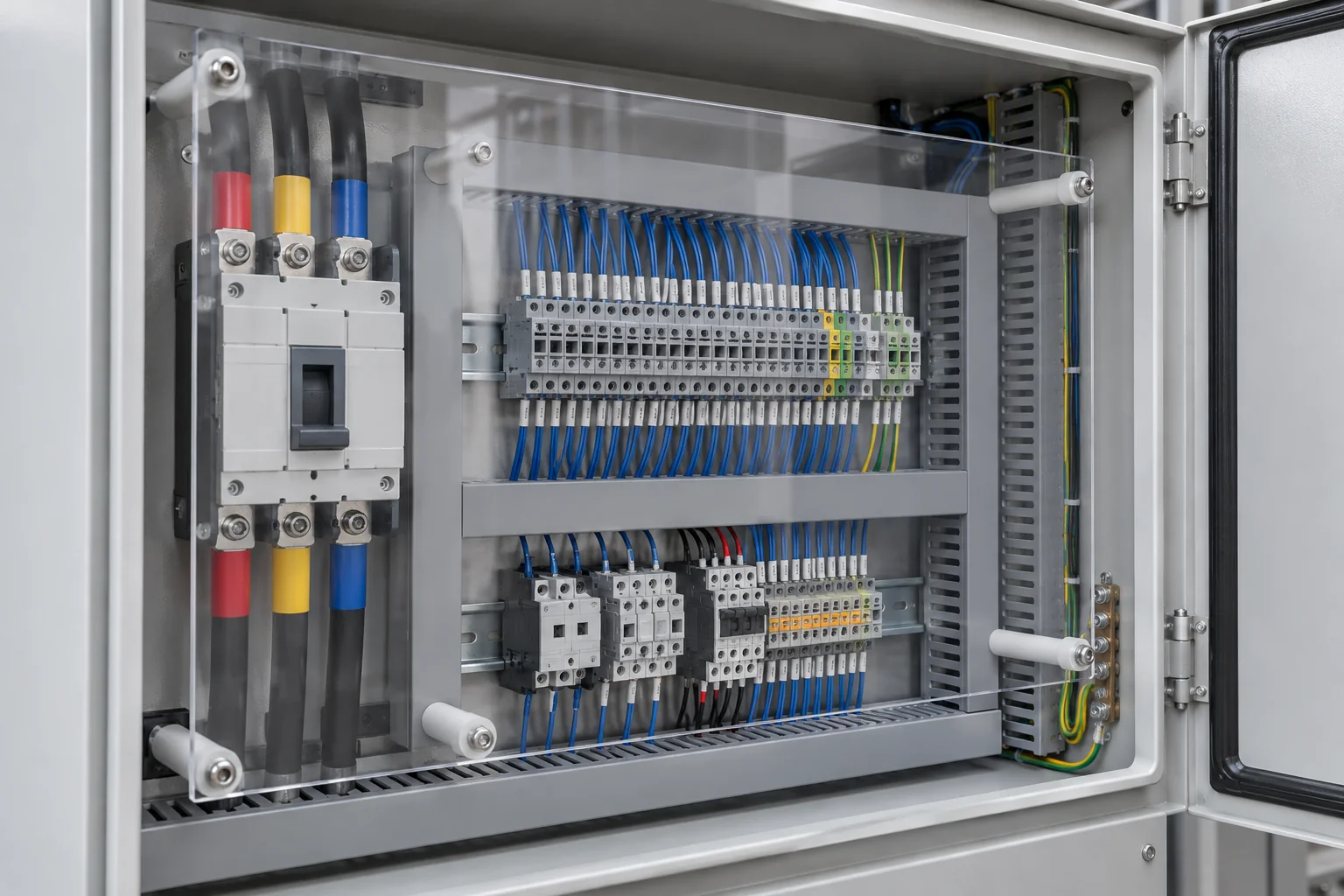
Insulating barriers for selected electrical equipment. Specify voltage, clearances, grade, flame requirements and access with the responsible electrical engineer.
Discuss this guard →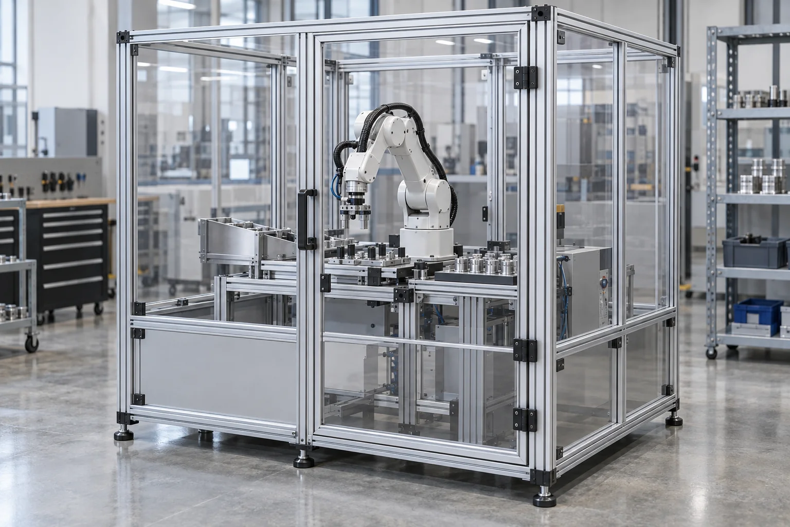
Panels for automation cells and machinery boundaries. Integrate with the specified frame, access doors, separation distances and safeguarding system.
Discuss this guard →
Opening guards with specified hinges, handles and latch or interlock interfaces. The safety design must determine when and how access is permitted.
Discuss this guard →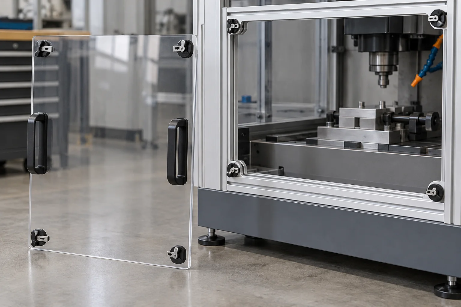
Service panels with defined lifting or handling features and specified retention. Identify tool-required or captive fasteners and safe removal procedures.
Discuss this guard →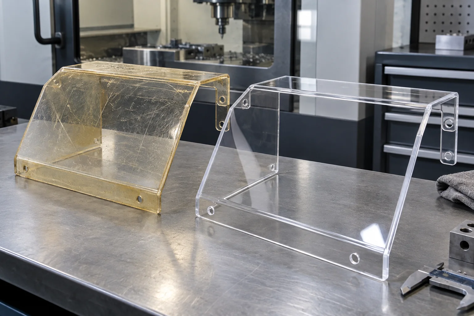
Reproduce documented geometry from existing CAD, old drawings, dimensions, sketches or physical samples, including damaged original guards where measurable.
Discuss this guard →Plastic machine guards are protective barriers, covers or shields used to separate operators from moving machine components, debris, fluids, electrical hazards or process areas while maintaining required access and visibility.
Transparent polycarbonate is commonly considered when process visibility and impact resistance are important. Electrical insulation and corrosion behavior must be assessed for the actual grade and operating environment. A transparent panel alone does not establish safe separation or containment.
Machine guards serve a different purpose from a plastic enclosure around a complete system or a structural plastic housing around a component. Plastic fabrication is the manufacturing route; the guard specification comes from the machine hazard assessment.
Polycarbonate combines clear viewing with useful toughness and fabrication options. Evaluate the exact sheet grade, thickness, coating, condition and mounting arrangement for the machine.
Often a stronger candidate than acrylic where impact is a concern. Material test data do not by themselves validate the finished guarding system.
Observe mechanisms and processes through the guard, reducing the need to open it for routine viewing. Define the required clear area.
Lower density can help with hinged or removable panels. Final weight depends on thickness, frame and hardware.
Many unfilled grades provide insulation, subject to thickness, environment and electrical design requirements. Do not assume a complete electrical safety rating.
Useful in suitable wet or chemically exposed environments. Review coolant, cleaner, oil, concentration, temperature and applied stress.
Route, drill, cut and form suitable grades into custom profiles, returns and covers. The sheet supplier guidance determines forming limits.
Impact performance varies with grade, thickness, test method, temperature, aging and exposure. Select documented material data for the actual project rather than a generic strength multiplier.
Polycarbonate is the main transparent option to review for impact-related guarding. Other polymers can suit opaque covers or lower-impact viewing applications when the safety design permits them.
| Material | Potential use | Main consideration |
|---|---|---|
| Polycarbonate | Transparent impact-related guarding | Scratching, chemical stress cracking and grade-specific performance |
| Hard-Coated Polycarbonate | Abrasion-exposed viewing surfaces | Higher cost; coating orientation and forming limitations |
| Acrylic / PMMA | Clear visual panels in lower-impact applications | More brittle; assess fracture and impact risk |
| HDPE | Opaque impact or chemical guard panels | No transparency; stiffness, creep and thermal movement |
| ABS | Opaque formed equipment covers | Grade-dependent temperature, stiffness and flame behavior |
| PVC | Selected chemical or electrical barriers | Grade, temperature, impact and exposure limits |
A coating may improve abrasion resistance without making every chemical or forming process acceptable. Obtain the exact supplier data, identify coated faces and agree the permitted cleaning method. Material family names do not prove food-contact, electrical or safety certification.
Locate the guard from the machine frame and the defined hazard envelope. Installation, opening travel and servicing must work with the complete safeguarding arrangement.
Dimension the pattern from machine datums. Specify edge distances, support, fastener contact and any allowance for thermal movement.
Define hinge locations, opening direction, travel and load support. Coordinate any guard switch or interlock interface with the safety engineer.
Position handles for controlled opening or removal without creating a new interference or trapping point. Review weight and handling clearance.
Specify the required retention method, including captive or tool-required fasteners where the safety design requires them. Avoid local over-clamping of the polymer.
Define openings for controls, tooling, maintenance or material loading. Their size and hazard separation must be reviewed as part of the safety design.
Check the moving envelope, vibration, service components and all opening positions. A nominal CAD clearance must remain adequate in operation.
Supply frame CAD or a dimensioned interface drawing together with hinge, latch, handle and switch part numbers. Indicate hardware supply and installation responsibility. A switch mounting hole is not a validated interlocking function.
Separate the structural mounting zones from the critical viewing zones. Viewing areas may need tighter cosmetic acceptance, protective film, abrasion-resistant coatings or controlled cleaning.
Mark the clear viewing envelope on the drawing. Agree acceptable scratches, haze, distortion and inspection lighting for that area.
Consider abrasion-resistant sheet for frequent cleaning or abrasive exposure. Review the exact coating compatibility with machining, bends and chemicals.
Retain suitable film during fabrication, handling and installation where practical. Identify when it must be removed and protect exposed edges.
Use the sheet supplier approved cleaner and method. Incompatible solvents or aggressive cleaning can cause crazing, haze or loss of clarity.
Visibility is an operating requirement. Plan periodic inspection and replacement criteria for scratched, cracked, yellowed or chemically damaged panels; the machine owner determines the maintenance procedure.
Choose construction around the machine envelope, mounting frame and approved safety specification. Forming and assembly details must suit the actual sheet grade.
CNC-cut sheet with rounded profiles, mounting holes, slots and access cutouts. Frame support and unsupported span remain important.
Returns, flanges and shaped covers can wrap around the equipment or add stiffness. Confirm bend radius, process, springback, coating and residual-stress limits.
Coordinate panels, brackets, hinges, handles and fasteners as a kit or agreed assembly. Control the interfaces and installation sequence.
Cold bending, line bending and thermoforming have different grade and geometry limitations. We review the appropriate fabrication route rather than assuming that every hard-coated or transparent sheet can be formed in the same way.
Machine guard thickness should not be chosen from a generic chart alone. It depends on the hazard being contained, panel dimensions, unsupported span, impact energy, mounting method, material grade and applicable safety requirements.
Identify flying debris, chips and potential tool or workpiece release. Splash protection and impact containment are different duties.
Define the unsupported area, support continuity, edge retention and fastening arrangement. Sheet thickness cannot compensate for an unsuitable frame.
The safety assessment must consider the release path, mass, velocity and credible operating or failure conditions.
Use relevant grade data and consider temperature, UV exposure, chemicals, aging, forming stress and damage.
The machine OEM or qualified safety engineer should specify the thickness and retention system and determine any testing or validation required. TOPS Plastics reviews whether the specified construction can be manufactured; we do not infer containment performance from thickness alone.
TOPS Plastics can fabricate guards to customer drawings and specified requirements. The machine owner, OEM or qualified safety engineer should determine the required guard design, material thickness, mounting, interlocks and applicable standards for the specific hazard.
| Responsibility | Scope |
|---|---|
| Hazard assessment | Machine owner / OEM and qualified safety personnel define hazards, tasks, access and protective measures |
| Guard specification | Responsible designer defines material, thickness, geometry, separation distances, frame and retention |
| Fabrication | TOPS Plastics reviews and manufactures the agreed drawing, material and supplied specification |
| System validation | Responsible integrator verifies installation, interlocks and complete safeguarding performance |
| Inspection and maintenance | Machine owner establishes inspection, cleaning, damage limits and replacement procedures |
Depending on jurisdiction and machine, references may include OSHA machine-guarding requirements, the ANSI B11 series, ISO 14120 for guards, ISO 13857 for safety distances, ISO 10218 for robotics and local machinery-safety regulations. The responsible safety specialist must identify the applicable requirements and editions.
Fabricating a panel to a drawing is different from certifying a guarding system. Do not treat a material certificate, hinge, switch interface or this product page as a declaration that a complete machine is OSHA or ISO compliant.
Start with the approved safeguarding concept, then define a fabrication-ready part and machine interface.
Guard geometry, openings and retention must follow the assessed hazard and operator tasks.
Show mounting datums, hole patterns, frame geometry and the complete moving envelope.
Review panel span and supporting frame. Bends, returns or external framing may be required by the design.
Use practical cutout radii and edge finishing to reduce stress concentration and handling damage.
Keep mounting hardware and unnecessary cutouts outside the critical observation area where practical.
Define removal, opening and service requirements together with the required isolation and interlocking arrangements.
Large plastic panels can move relative to metal frames. Agree mounting allowances without compromising retention.
List coolant, cleaners, oils and other chemicals, including concentration, temperature and cleaning frequency.
The fabrication route follows the approved material, flat pattern, formed geometry, hardware and inspection requirements.
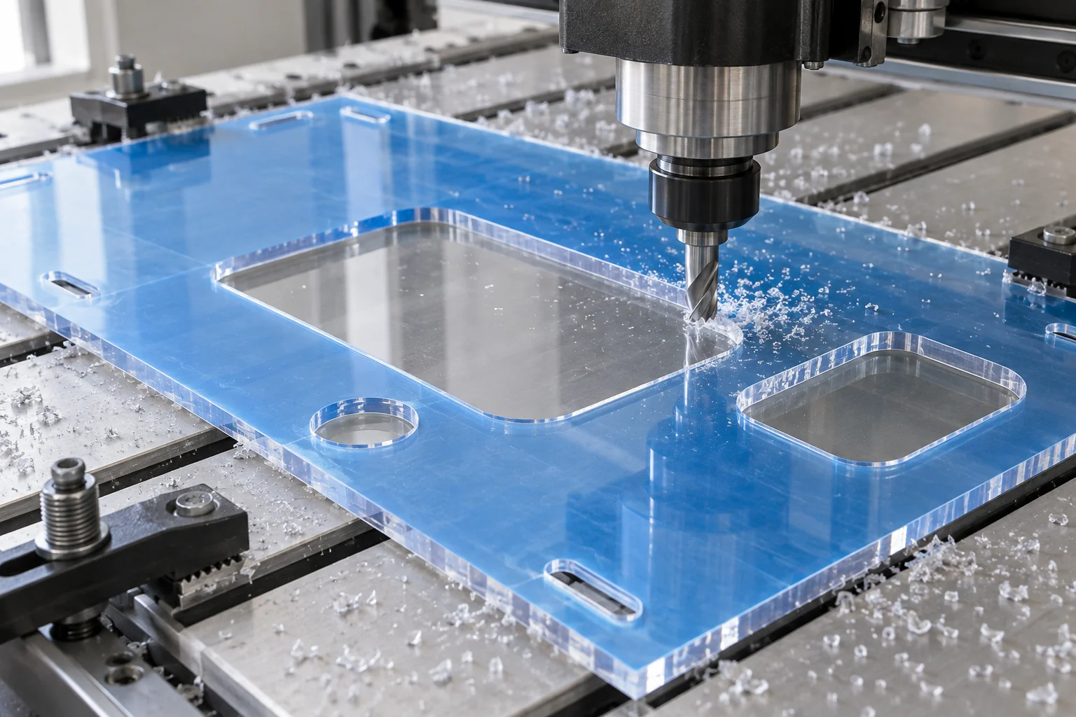
Produce outer profiles, mounting holes, slots, access openings and specified ventilation features. Review tool access and protected viewing surfaces.
Machine drawing-defined interfaces for fasteners and hardware. Control location and edge condition.
Make specified flanges, returns and shaped covers using a process compatible with the grade, thickness and coating.
Install agreed hinges, handles, fasteners, brackets and labels to the specified BOM and method.
Coordinate multi-panel kits and agreed assemblies, with defined frame interfaces and component identification.
Check dimensions, hole position, bend geometry, viewing condition and agreed assembly fit before protective packing.
Cutting method depends on the polymer and edge requirements. CNC routing is often appropriate for polycarbonate; laser cutting is a separate process that requires material-specific review and is not assumed suitable for every guard.
Yes, where the geometry and material requirements can be adequately documented. A replacement can be reviewed from an existing drawing, dimensioned sketch, CAD model or physical sample.
Document the original geometry and failure location. The responsible engineer should review whether the cause affects the replacement specification.
Review visibility, grade, outdoor exposure and cleaning history before specifying a new panel.
Reconstruct measurable interfaces for discontinued machinery while identifying missing or uncertain requirements.
Record the revised drawing and have the access change reviewed within the machine safeguarding design.
A damaged sample may be distorted or incomplete. Confirm critical dimensions, nominal shape, material grade, thickness, mounting and hardware before releasing a replacement drawing.
Reproducing geometry does not automatically validate the original guard against current safety requirements. Changes to material, thickness, opening, mounting or access require review by the responsible machine safety designer.
Consider polycarbonate when visibility, lower weight, insulation or suitable corrosion resistance matter. Metal may be better where high stiffness, elevated temperature or specific containment requirements dominate. The hazard assessment controls the final choice.
| Factor | Plastic / Polycarbonate | Metal |
|---|---|---|
| Visibility | Clear viewing with suitable transparent grades | Mesh or a designed window may be needed |
| Weight | Often lower density; thickness and frame affect final mass | Usually greater density; section design matters |
| Electrical isolation | Many grades are insulating; verify design and environment | Generally conductive; isolation may be required |
| Corrosion | Polymer and chemical compatibility dependent | Alloy and coating dependent |
| Impact stiffness | Lower stiffness; toughness and support need assessment | Often higher stiffness; containment still needs validation |
| High temperature | Grade-specific limits and thermal movement | Often better suited, depending on alloy and conditions |
| CNC customization | Profiles, holes and formed features where suitable | Profiles, holes and fabricated features where suitable |
| Washdown / chemical use | Grade, cleaner, stress and temperature dependent | Alloy, coating and cleaner dependent |
Neither transparency nor high stiffness proves containment. Evaluate the complete panel, frame, fasteners, joints, openings and credible release scenario.
Examples describe fabrication uses. The responsible designer specifies guarding performance, environmental suitability and project documentation.
Viewing panels and splash or chip guards with the specified containment and chemical requirements.
Protective covers around moving mechanisms, coordinated with machine access and interlocks.
Robot-cell panels and equipment shields within a properly engineered safeguarding system.
Point-of-operation and drive-system guards with defined loading and maintenance access.
Washdown-compatible guarding in specified documented grades, with hygienic design and cleaner compatibility reviewed.
Assembly-line and automation guard panels with controlled frame and service interfaces.
Transparent equipment covers and guards with defined cleaning, visibility and documentation requirements.
Inspection verifies the released fabrication requirements. Agree the sampling, reports, fixture or machine-interface checks and surface acceptance before production.
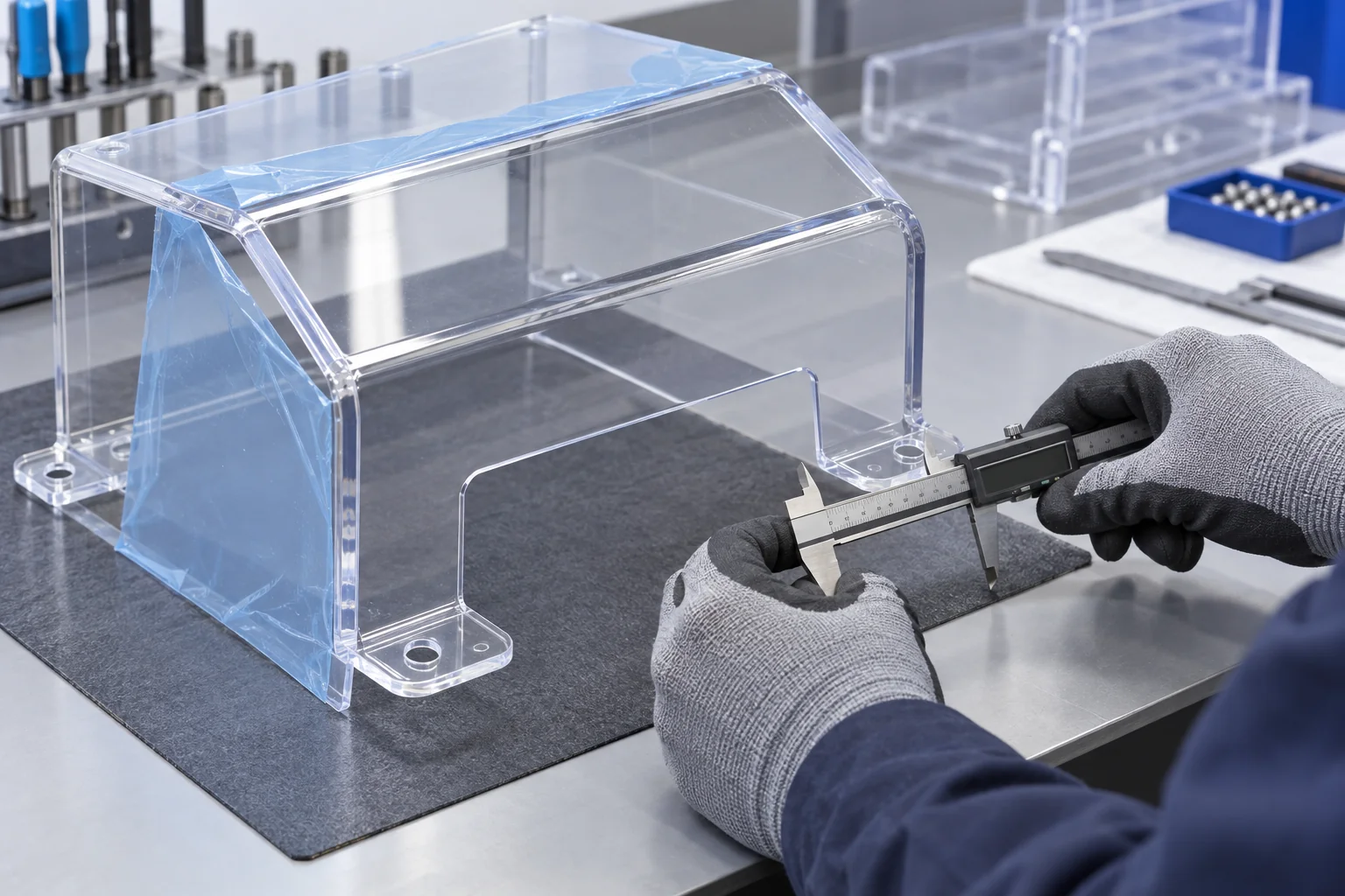
Check the specified stock, thickness, coating and required supplier documentation.
Confirm revision, flat pattern, formed geometry, mounting datums and supplied hardware.
Measure the outline, cutouts, slots and hole pattern against the drawing.
Check specified angles, returns, radii and overall formed dimensions.
Verify fastener interfaces, support areas and required clearances.
Check scratches, haze, cracks, edge damage and coating orientation where coated sheet is specified.
Check part numbers, mounting locations, opening movement and agreed installation requirements.
Use the agreed frame, template or supplied mating parts where included in scope.
Protect clear viewing faces, formed corners and hardware during transport.
Dimensional and visual inspection does not replace installed-machine safety validation, impact containment testing or interlock verification. Agree these responsibilities and acceptance requirements separately.
Keep the machine interface and approved specification controlled from the first guard through repeat supply.
Evaluate machine fit, mounting geometry, visibility and access. The responsible integrator validates the safeguarding arrangement before operation.
Produce documented maintenance, retrofit or specialized-machine parts after material and design review.
Control drawing revision, material grade, thickness, hole pattern, bends, viewing acceptance and hardware BOM.
A guard is more than a clear sheet. Hazard type, grade, span, mounting, visibility, access and environmental exposure determine whether the specified construction suits the machine.
Work from released CAD, drawings and documented machine interfaces.
Review routing, drilling and forming against the actual grade and geometry.
Coordinate holes, slots, bends, cutouts and access features.
Define cosmetic acceptance and protect important clear surfaces.
Agree hinges, handles, brackets, fasteners and installation scope.
Review measurable original guards, sketches and obsolete equipment interfaces.
Maintain approved revisions across development and subsequent orders.
Check the agreed geometry, surface condition and assembly interfaces.
Answers about materials, thickness, machine interfaces, replacement guards and safety-design responsibility.
They form barriers or shields around moving mechanisms, process areas, debris or other specified hazards while allowing required visibility and access. The complete guard and its installation must follow the machine risk assessment.
Polycarbonate is commonly reviewed for transparent impact-related guarding. Hard-coated PC, acrylic, HDPE, ABS or PVC may suit particular duties. Choose the exact grade from the hazard, span, exposure, thickness and safety specification.
Polycarbonate generally offers greater impact toughness, while acrylic can suit lower-impact viewing applications. Neither material is automatically suitable for a specific hazard. Review grade data, fracture behavior, exposure and complete mounting design.
It depends on the hazard and engineering assessment, including release energy, panel dimensions, unsupported span, material grade, frame and retention. The responsible machine safety designer should specify thickness and any required testing; there is no universal safe thickness chart.
Suitable grades can be routed, drilled and formed into flat, bent or multi-part guards. Review bend radius, thickness, coating and supplier processing guidance before confirming the fabrication route.
Yes, where its geometry and required specification can be documented from CAD, drawings, sketches or samples. Confirm dimensions that are missing or distorted. Reproduction does not validate the original safety design.
Yes, specified hinges, handles, fasteners, brackets and switch interfaces can be reviewed for inclusion. The safety designer determines access control and interlocking requirements; installed hardware alone does not establish safe operation.
Selected grades can provide insulating barriers, but voltage, clearances, flame behavior, thickness, environment and access require electrical engineering review. A clear PC panel is not by itself an electrical safety certification.
A guard can be fabricated to an engineered specification addressing applicable requirements. Compliance depends on the complete design, installation, machine hazards and validation. TOPS Plastics fabrication to a drawing is separate from certifying the guarding system.
We can review CAD, DXF, dimensioned drawings, sketches and measurable samples. Provide machine interfaces, material and thickness, hardware, viewing and access requirements, hazard information and the approved safety specification.
YOUR MACHINE. YOUR GUARD SPECIFICATION.
Upload your guard drawing, CAD model, sketch or reference photos and provide the material, machine type, dimensions, mounting method, access requirements, hazard information and applicable safety specification. We can review fabrication requirements and provide a manufacturing quotation.
Company, name, email and phone are required. Country, part number, quantity and drawing upload are optional. Include the technical and safety specification in your drawing package or send it by email.
info@tops-precision.comSTEP / STP / IGES / X_T / DWG / DXF / PDF or ZIP, maximum 10 MB. Larger packages can be shared by email. Agree confidential-file handling before sending sensitive drawings.