01
Plastic Electronics Enclosures
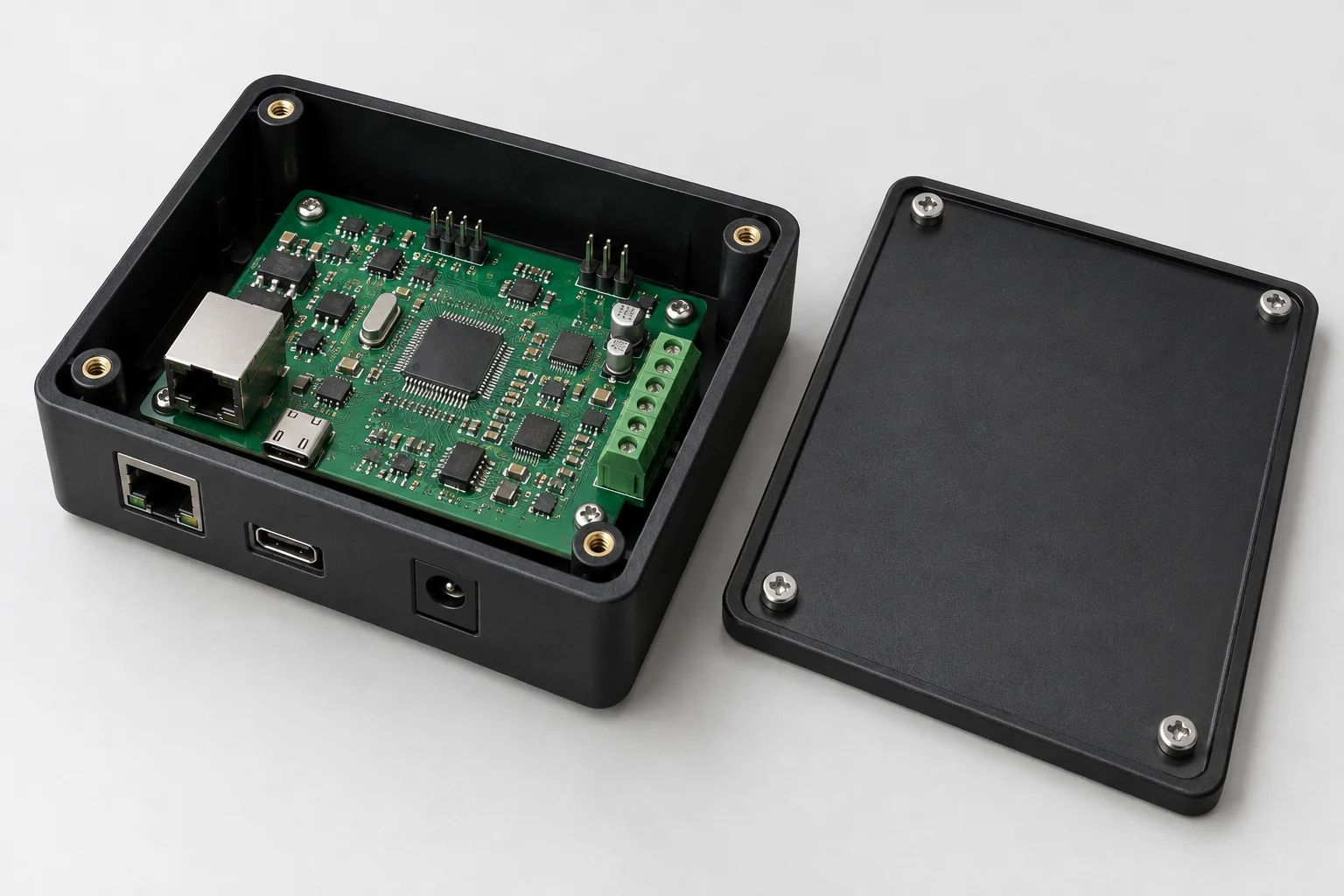
Protect PCBs, controllers, IoT modules and embedded systems. Define board supports, connector access, cable space and the enclosure mounting pattern.
Discuss this enclosure →
BUILT AROUND WHAT GOES INSIDE.
TOPS Plastics manufactures custom plastic enclosures for electronics, sensors, instruments, automation and industrial equipment. We machine and fabricate internal cavities, PCB mounting bosses, cable entries, connector cutouts, display windows, inserts and assembly features from your CAD model and drawings.
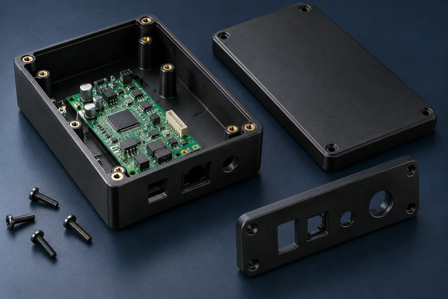
Start with the components the enclosure must accommodate. We review geometry, material, interfaces and assembly before confirming the manufacturing scope.
| Design item | Project requirements |
|---|---|
| Enclosure types | Electronics, instrument, control, sensor, transparent and industrial enclosures |
| Materials | ABS, Polycarbonate, Acrylic, POM, PEI and other specified engineering plastics |
| Machined features | Internal cavities, bosses, windows, cable entries, ventilation slots and connector ports |
| Hardware | Specified inserts, screws, hinges, brackets and gaskets, subject to assembly review |
| Processes | CNC milling, drilling, tapping, routing, bonding and assembly as appropriate |
| Production | Prototype, low-volume and repeat production to controlled revisions |
| Design input | 3D CAD, 2D drawings, PCB outlines and internal component dimensions |
| Inspection | Dimensions, mating fit, cosmetic surfaces and agreed assembly checks |
Choose the enclosure construction around your component layout, access needs and operating environment. Each design is made to the approved drawing.
Protect PCBs, controllers, IoT modules and embedded systems. Define board supports, connector access, cable space and the enclosure mounting pattern.
Discuss this enclosure →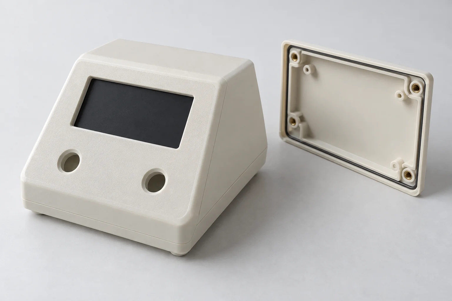
Custom cases for measurement, laboratory and diagnostic instruments, with display openings, controls and access to internal components.
Discuss this enclosure →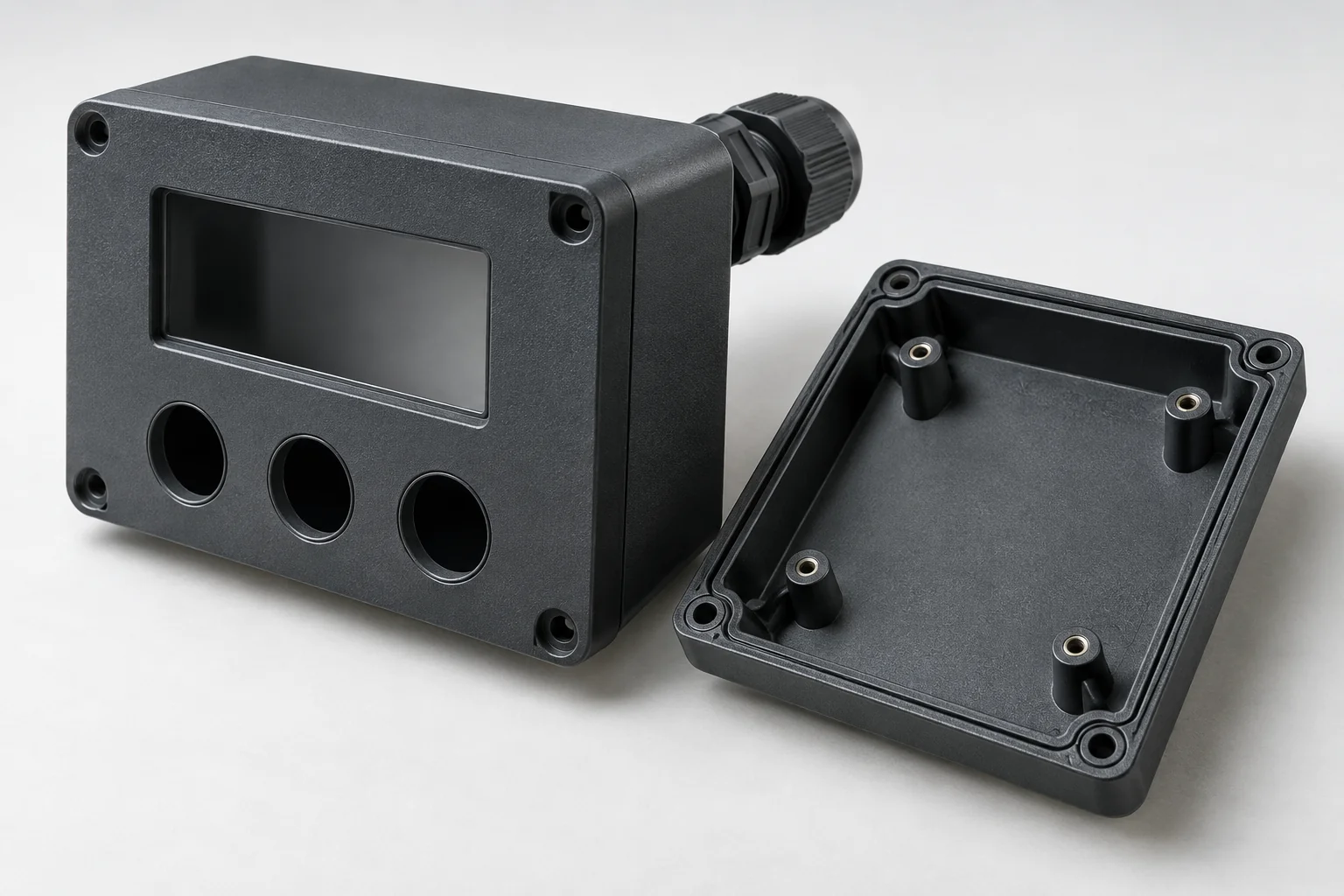
Bring switches, displays and control boards together in an enclosure designed around the operator interface and automation installation.
Discuss this enclosure →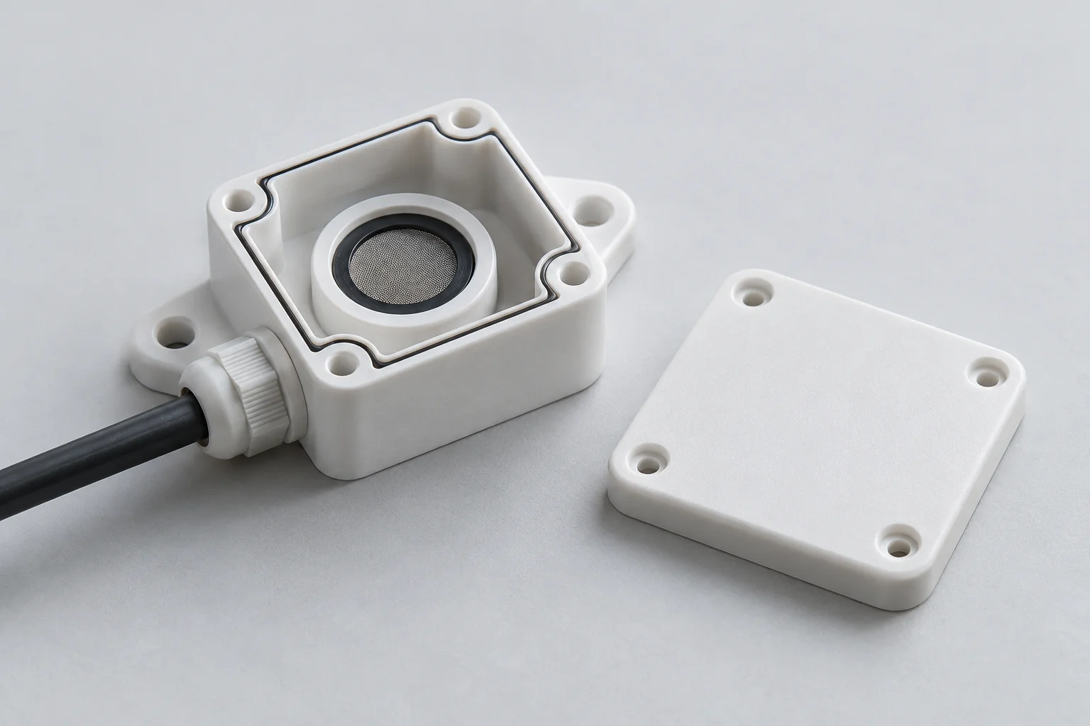
Compact protective bodies for probes, sensors and monitoring devices. Specify the sensing opening, cable entry, mounting and environmental exposure.
Discuss this enclosure →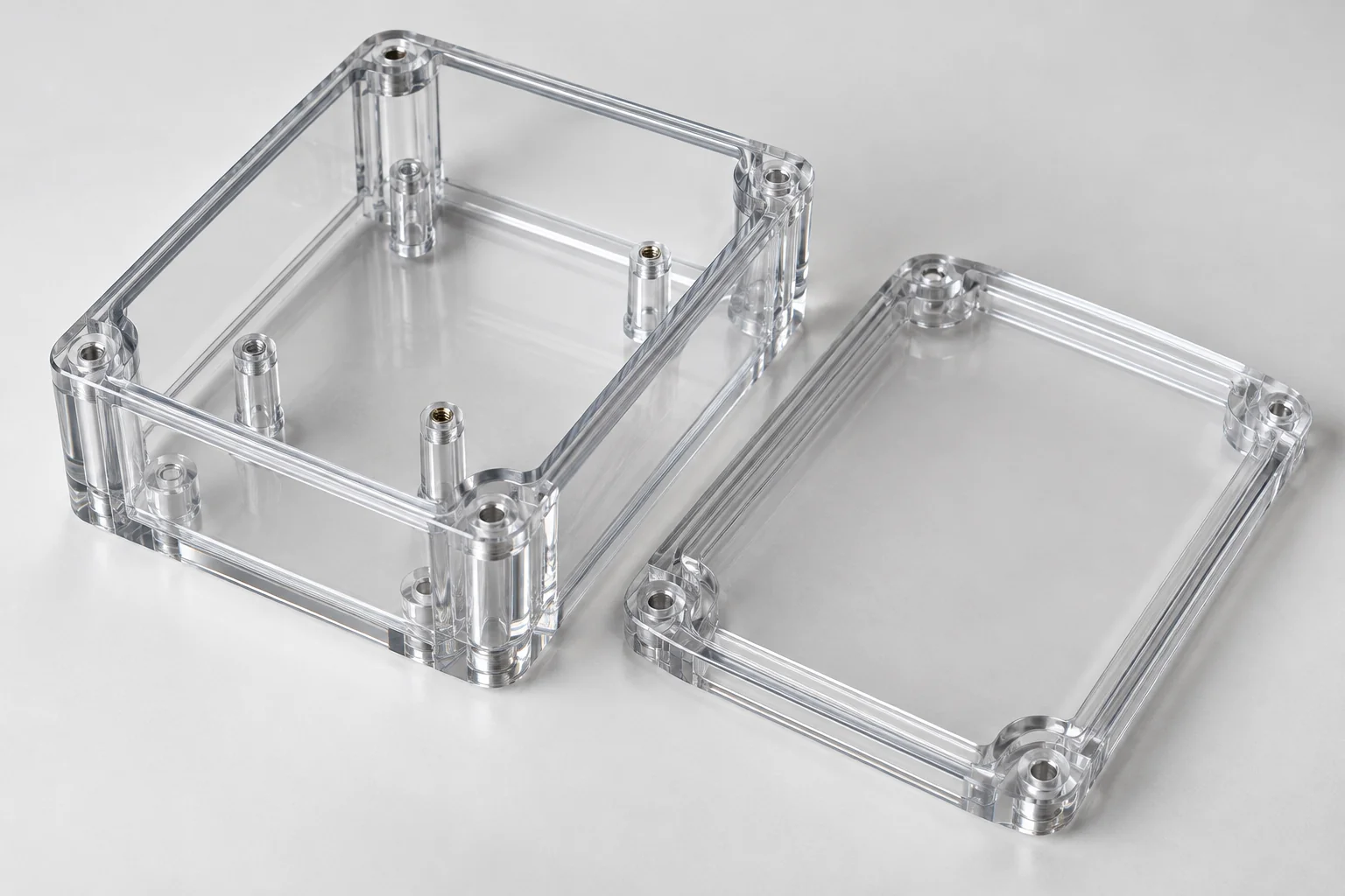
Acrylic or Polycarbonate covers and boxes provide visibility of displays and internal equipment. Choose the grade for impact, chemical and optical requirements.
Discuss this enclosure →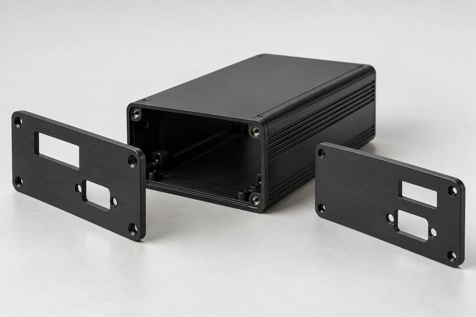
Front and rear panels with display windows, connector cutouts and removable service access, matched to the enclosure body and internal layout.
Discuss this enclosure →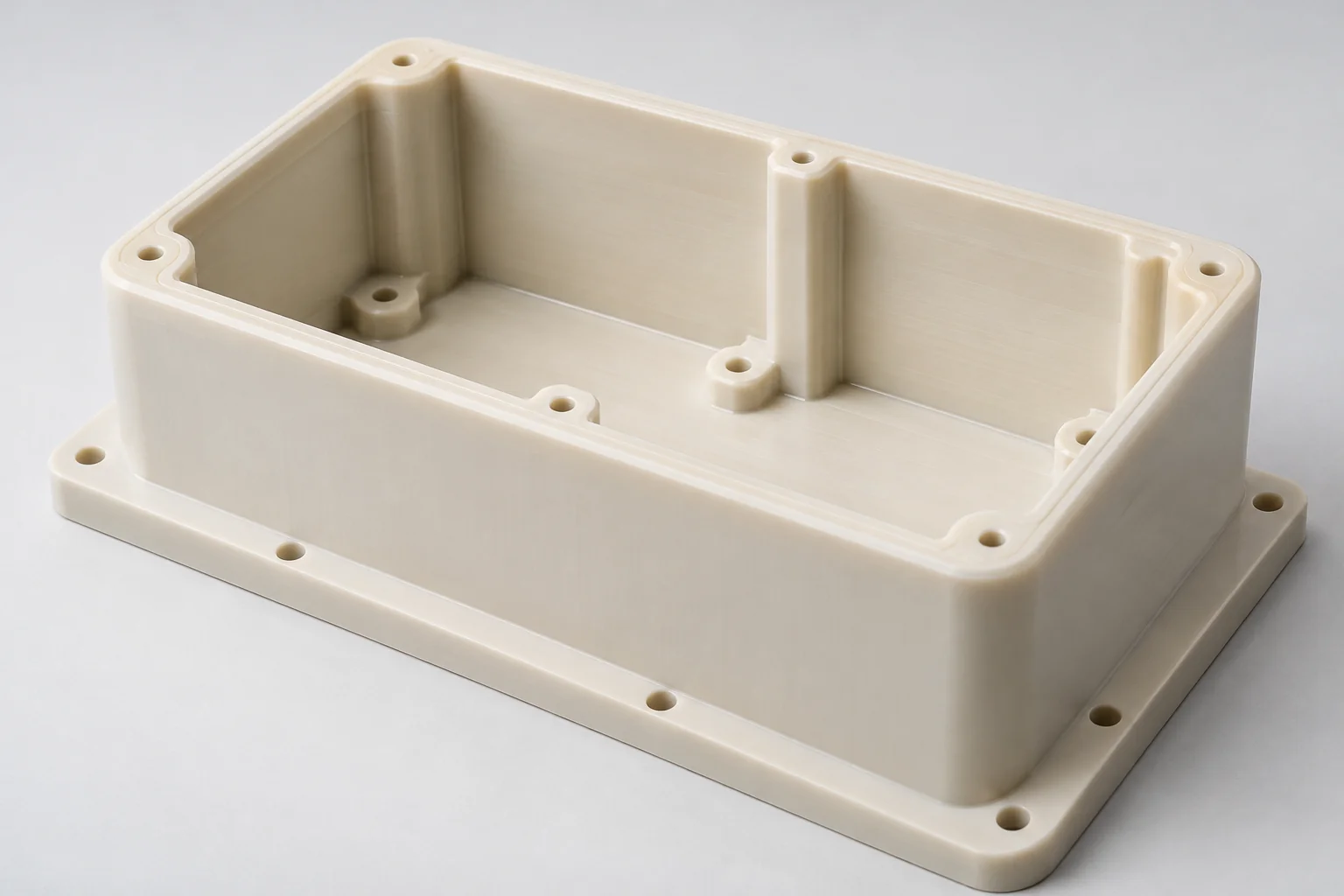
Custom protective covers around mechanisms or electronics, with mounting flanges, openings and access features suited to the installed equipment.
Discuss this enclosure →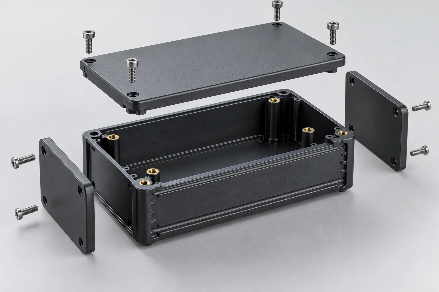
Bases, lids, frames and removable panels manufactured as a coordinated assembly. Define mating datums, hardware and the sequence of assembly.
Discuss this enclosure →Custom plastic enclosures are protective boxes or cases made around a specific electronic assembly, instrument or piece of equipment. Their cavities, mounting features, cable paths and access panels follow the installed components rather than a standard catalog size.
A complete enclosure combines the body, lid or panels and specified interfaces. A plastic housing is a broader structural body or casing and may remain open; a machine guard is a barrier around machinery. These parts have different design and inspection priorities.
CNC machining is useful when quantities are low to moderate, geometry is unusual or the design is still evolving. The preferred process depends on size, material, access, cosmetic expectations and the total project cost.
Machining lets the enclosure follow the product layout while avoiding a dedicated injection mold. Tool access, stock size and assembly requirements still need review.
Machine from stock without an injection mold. Fixtures, setup and programming may still be needed.
Update released CAD to move a connector, change a cavity or revise a panel before the next manufacturing run.
Combine pockets, mounting bosses, recessed panels and accessible side features in a drawing-defined body.
Specify actual ABS, POM, PC, PEI or PEEK stock grades. Machining stock and injection molding resin grades are not automatically interchangeable.
Control the locations and fits that matter to PCB mounting, connectors, lids and hardware rather than applying a tight tolerance everywhere.
Compare setup and unit costs for the expected order pattern. Machining can suit specialized equipment without committing to a mold.
Select the exact grade for impact, temperature, chemicals, electrical requirements, appearance and machining behavior. Material family names alone do not establish flame performance or system compliance.
| Material | Useful characteristics | Typical enclosure applications |
|---|---|---|
| ABS | Machinability, practical cost and suitability for specified coating systems | Electronics cases, prototypes and instrument panels |
| Polycarbonate | High impact resistance and available transparent grades | Protective covers, windows and equipment enclosures |
| Acrylic / PMMA | Optical clarity and polished appearance; lower impact toughness than typical PC grades | Display cases and transparent covers |
| Delrin / POM | Machinability and dimensional stability under appropriate conditions | Precision instrument bodies and mounting features |
| Ultem / PEI | Heat resistance and electrical insulation; flame data are grade and thickness specific | Higher-temperature electrical and instrument applications |
| PEEK | Temperature and chemical performance in specified grades | Demanding process and equipment enclosures |
| PVC | Chemical resistance and electrical insulation within grade limits | Process equipment and electrical covers |
| Polypropylene / HDPE | Chemical resistance and low moisture uptake; stiffness and thermal movement need allowance | Wet-process and chemical equipment covers |
Check supplier data for the exact grade, thickness and service conditions. A resin flame classification does not certify the finished enclosure; UV exposure, stress cracking, temperature and cleaning agents also influence material selection.
Begin with the PCB and component envelope, then work outward to walls, connectors, fasteners and service access. Allow for manufacturing variation and installed cable movement.
Locate the board on its mounting points. Check connector access at the wall, route the cable clear of the lid and keep the service area reachable.
Specify mounting-hole positions, boss diameter and height, and whether the joint uses a screw, standoff or insert. Keep sufficient surrounding material for the chosen fastening method.
Reserve space for connectors, cable plugs, heat sinks, displays, batteries and sensors. Include insertion travel and electrical clearances defined by the product design.
Set pocket depth and wall thickness around the internal assembly. Deep, narrow pockets increase tool-access difficulty and may leave flexible walls.
Include connector backshells, strain relief and cable bend radius. A cable that fits before lid installation may be trapped when the enclosure closes.
Make fasteners and connectors reachable in the intended sequence. Plan how the board, hardware and lid will be installed and removed for service.
Review the enclosure together with a PCB outline and component-height model. The layout below is conceptual: it does not define electrical clearance, dimensions or an approved assembly design.
Dimension the actual mating component and its required access envelope. Standard connector names alone do not define the cutout or fastening pattern.
USB, D-sub, circular and custom connector openings with drawing-defined locating and mounting features.
LCD, LED, touchscreen and indicator openings; define visible area, bezel support and any separate window.
Gland, grommet and cable-pass openings, with the specified hardware and strain-relief arrangement.
Openings for the thermal design. Ventilation changes dust, moisture and access protection and must be assessed with the product.
Round or shaped openings for controls, including anti-rotation features, mounting faces and operating clearance.
Optical, proximity and environmental sensor access matched to the sensing function and exposure conditions.
Drawing-defined part numbers or control markings. Confirm method, contrast and durability; printing and special finishes require separate review.
Pockets for membrane keypads, nameplates or front panels, with controlled depth and practical internal corner radii.
Choose the closure around access frequency, material flexibility, fastener loads and sealing requirements. Establish the lid-to-body datums and a workable assembly sequence.
A straightforward removable closure. Specify screw type, engagement, spacing and the material around each fixing.
Use specified inserts where repeated opening or joint requirements justify them. Boss geometry and installation method must suit the polymer.
Feasibility depends on material strain capability, flexure geometry and machining access. Do not transfer a molded snap design directly to machined stock without review.
Define hinge location, opening envelope, retention and clearance to nearby equipment. Confirm the supplied or installed hardware scope.
Provide practical slide clearance and retention while allowing for thermal movement, wear and the intended access direction.
Separate interface panels simplify connector or display revisions. Control panel location, fixing and any perimeter seal.
Seal design brings the body, lid, fasteners and all penetrations together. A gasket alone does not establish an IP rating.
Specify the seal, groove dimensions, mating finish and compression from the seal supplier design. Account for enclosure stiffness and movement.
Define gasket material, thickness, contact width and allowable compression. Check the joint around corners and fastener locations.
A compatible bonding process can join selected materials. Surface preparation, joint geometry and inspection must be agreed; bonded access is less serviceable.
Fastener spacing, torque and local support influence uniform seal loading. Avoid damaging the plastic while achieving the required joint compression.
Dust or moisture protection depends on the full assembly, including windows, cable glands, connector interfaces, vents and closure tolerances. Specify the target protection level and validation plan. IP65 or IP67 must not be assumed from the presence of a gasket; a rating requires appropriate testing of the defined enclosure configuration.
Specify hardware part numbers, supplier drawings, installation requirements and responsibility for procurement. TOPS Plastics can manufacture components and support agreed assembly operations where the project scope allows.
Match insert geometry and installation method to the exact plastic and boss design.
Define type, length, engagement and any controlled tightening requirements.
Review opening travel, mounting footprint and lid support.
Coordinate the enclosure-to-machine interface and load path.
Set PCB or component height and avoid interference with underside features.
Identify handling loads and reinforcement at the attachment points.
Specify material compatibility, joint compression and service life expectations.
Supply the board hole pattern and hardware stack height.
Match cable size, panel thickness, thread and required sealing arrangement.
Define material, optical area, retention and any window-to-body seal.
Control the interfaces that determine assembly. Choose achievable tolerances around the material, size, wall stiffness, temperature and inspection method.
| Design item | Project requirements |
|---|---|
| PCB boss position | Board mounting alignment and connector location relative to enclosure datums |
| Connector cutout | Mating connector outline, mounting pattern and plug insertion space |
| Display opening | Visible area, bezel fit and alignment to the display assembly |
| Lid fit | Locating features, perimeter gap and assembly freedom |
| Gasket groove | Seal cross-section, compression and the mating surface relationship |
| Internal cavity | Component envelope, assembly clearance and pocket depth |
| Hole position | Fastener, bracket and panel mounting relationships |
| Flatness | Lid, panel and sealing-face contact in the defined measurement state |
| Wall thickness | Stiffness, fastening support and remaining material around pockets |
Mark critical dimensions and datums on the drawing. Agree whether measurements apply free-state or assembled, after stabilization, and at what environmental conditions. Avoid a blanket tight tolerance that adds cost without improving fit.
Design the case and its contents together. Early interface review helps prevent an attractive enclosure that is difficult to machine, close or maintain.
Use actual PCB outlines and component heights, including connectors and service envelopes.
Provide stiffness for machining, handling, fasteners and the installed environment.
Allow cutter radii in corners; identify where a mating part truly requires a different solution.
Review deep pockets, side features, undercuts and access to every machined surface.
Locate board bosses, cutouts and lid features from consistent functional references.
Assess heat generation, ventilation and thermal paths at product level; plastic typically offers limited heat conduction.
Allow adequate wall and boss support, edge distances and controlled installation loads.
Mark visible surfaces, allowable tool marks, scratch limits and any finish before manufacturing.
Select machining and fabrication processes to suit the body, panels, material and agreed assembly requirements.
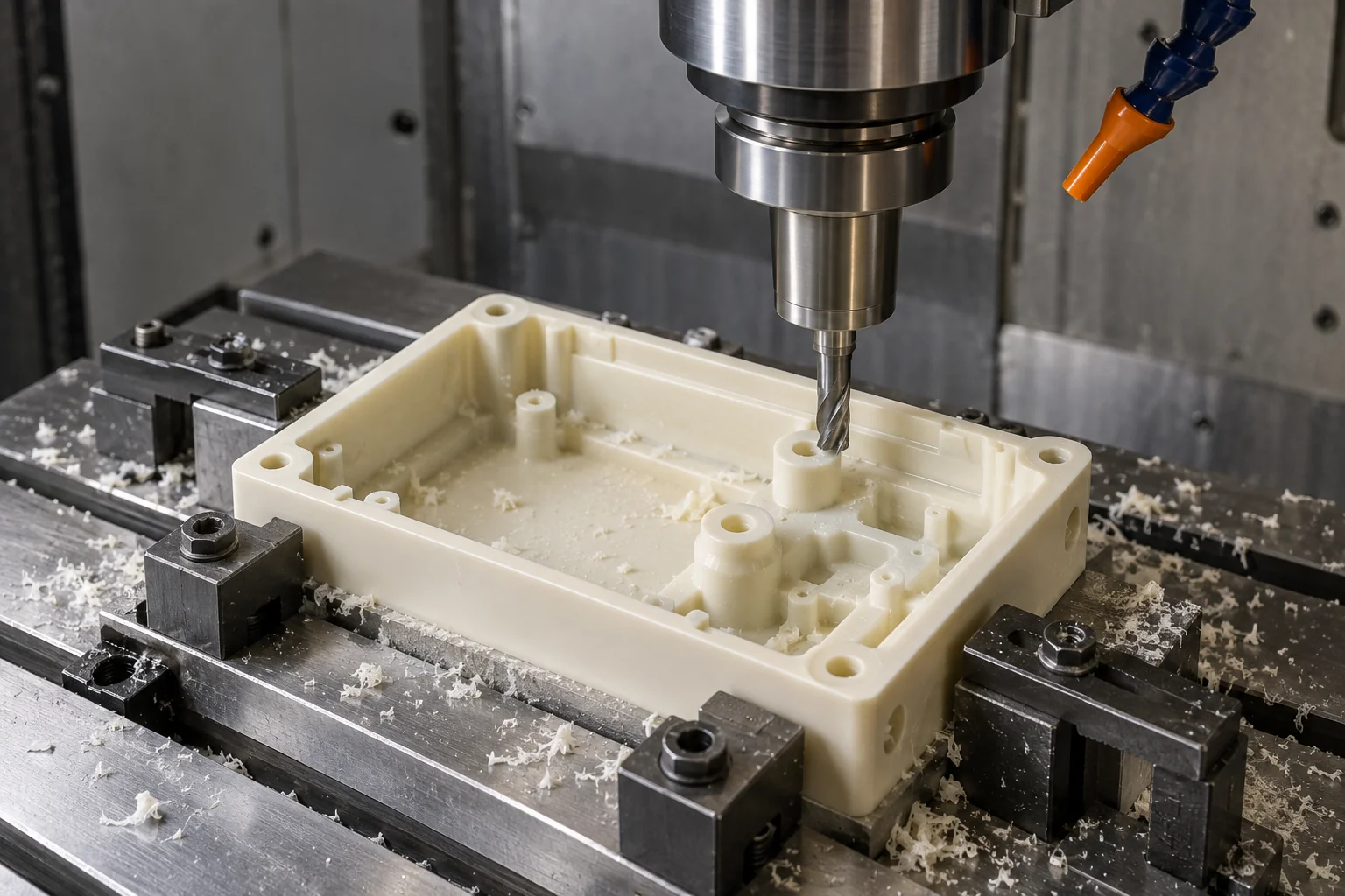
Machine outer profiles, internal cavities, PCB bosses, recesses and accessible cutouts from specified plastic stock.
Produce fastening holes, insert preparations, PCB mounting patterns and cable or connector features to the drawing.
Cut sheet panels and covers where the design suits routed stock and fabricated construction.
Join compatible materials and install specified components using a reviewed joint and assembly plan.
Review suitable processes for Acrylic or Polycarbonate windows and visible surfaces. Material, stress and optical expectations govern the choice.
Check body-to-lid fit, panel interfaces and agreed hardware installation against the released drawing and assembly requirements.
Compare the total project: geometry, quantity, design maturity, grade, finish and repeat demand. Neither process is the automatic choice for every enclosure.
| Factor | CNC machined enclosure | Injection molded enclosure |
|---|---|---|
| Tooling | No dedicated injection mold; setup and fixtures may apply | A mold and molding development are required |
| Prototype | Useful for functional fit and geometry revisions | Molded samples follow tooling or prototype tooling |
| Low volume | Can suit small runs and specialized equipment | Tooling amortization may dominate small orders |
| Design changes | Revise CAD, programming and any affected setup | May require mold modification or replacement |
| Internal features / cutouts | Limited by cutter reach, access and fixturing | Limited by mold release, cores, draft and parting strategy |
| High-volume unit cost | Machining time continues for each part | May offer lower unit cost at sufficient stable demand |
| Material selection | Available machining stock grades and sizes | Molding resin grades and processing requirements |
Request a process review for the expected lifetime quantity and revision plan. A machined prototype can validate assembly, but it does not reproduce every property, wall detail or manufacturing effect of a molded production enclosure.
Choose around the installed requirements. Plastics can offer insulation, lower weight, visibility or RF access; metals can offer stiffness, thermal conduction and conductive shielding.
| Factor | Plastic enclosure | Metal enclosure |
|---|---|---|
| Weight | Often lower density; actual weight depends on wall design | Often heavier for a comparable geometry |
| Electrical insulation | Many grades are insulating; verify application data | Conductive bodies need appropriate isolation and grounding |
| Corrosion | Compatibility depends on polymer, chemical and stress | Resistance depends on alloy, finish and environment |
| EMI shielding | Usually needs conductive treatment or an additional shielding solution | Conductive body helps, but seams, apertures and grounding still matter |
| Machining / customization | Custom pockets, windows, bosses and panels | Also readily customized; process and finish depend on alloy |
| Extreme temperature | Grade-specific limits and thermal movement need review | Often preferable for higher temperature or heat dissipation |
| Transparency | Clear Acrylic or PC can provide visibility | A separate transparent window is required |
| RF transparency | Selected unfilled polymers can suit antenna access; verify frequency and geometry | Conductive walls may impede radio signals without a designed aperture |
EMI, thermal and environmental behavior must be validated for the complete product. A metal enclosure is not automatically compliant, and a plastic enclosure cannot be assumed RF-transparent in every grade or configuration.
Application examples identify design priorities rather than certify a finished product. Share the equipment requirements and any required documentation.
Controllers, embedded modules and connected equipment with board, connector and antenna requirements.
Control interfaces, sensors and machine-mounted enclosures with vibration, access and mounting constraints.
Instrument and diagnostic cases to project-defined material, cleaning and documentation requirements; suitability requires application review.
Display, connector and control interfaces with repeatable internal positioning and service access.
Specified materials and surface handling for equipment modules; cleanliness and traceability must be agreed.
Cases and covers designed for the actual reagents, cleaning method and operating temperature.
Operator panels and equipment enclosures with defined wiring, mounting, heat and exposure conditions.
The inspection plan follows the functional and cosmetic interfaces on the released drawings. Confirm sampling, reporting and any assembly fixtures before production.
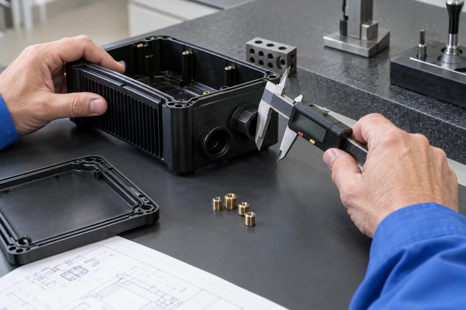
Check specified stock grade and required supplier documentation.
Confirm revision, component envelope and the agreed critical interfaces.
Check connector, display and control openings against dimensions and datums.
Check mounting positions, heights and board-support relationships.
Assess locating features, closure gap and panel alignment in the specified state.
Check specified parts, locations and installation requirements.
Review visible faces and agreed limits for scratches, haze, cracks and polishing quality on clear parts.
Verify agreed mating components or gauges where provided and included in scope.
Protect visible surfaces, corners, windows and installed hardware during shipment.
Dimensional and assembly checks do not establish an IP, EMC or product safety certification. Environmental or electrical qualification requires a separately defined test plan and the appropriate facilities.
Carry the approved interfaces and inspection requirements forward as the enclosure moves from design validation to recurring supply.
Validate component fit, connector placement, display alignment and the assembly sequence. Record changes in the released drawings.
Support specialized equipment with machining or fabrication without dedicated mold tooling when the geometry and economics fit.
Control the CAD revision, approved BOM, machining program, finish references and inspection standards. Review changes before the next run.
Internal component layout, connector access, wall thickness, fastening, sealing, thermal management and assembly sequence determine whether a custom enclosure works in the final product.
Review the enclosure against your drawing and component layout.
Consider machined construction for development and suitable production quantities.
Match the specified grade to the operating conditions and drawing requirements.
Coordinate cavities, mounting bosses and board support.
Manufacture accessible interfaces for connectors, displays and controls.
Review inserts, hardware and assembly as a defined project scope.
Maintain approved revisions and documented assembly interfaces.
Define functional fits and visible-surface acceptance together.
Practical answers about enclosure materials, PCB mounting, windows, seals and manufacturing routes.
Custom plastic enclosures are protective cases made around specific components or equipment, with drawing-defined cavities, mounting features, openings, lids and panels rather than a fixed catalog size.
ABS, Polycarbonate, Acrylic, POM and PEI are useful options for different requirements. Select an exact grade for impact, temperature, electrical insulation, chemicals, appearance and any specified flame performance.
Yes. Suitable enclosure bodies and panels can be machined from stock without an injection mold. Setup, programming and fixtures may still be required, and geometry must allow tool access.
Yes, drawing-defined bosses and insert preparations can be reviewed for machining and agreed installation. Provide the PCB mounting pattern, height, fastener or insert specification and surrounding component clearances.
Yes. Provide the component drawing, opening size, mounting pattern, insertion space and any separate window or seal requirements.
An enclosure is a protective box or case around equipment, generally with a lid or panels. A housing is a broader structural casing or body and does not necessarily form a closed protective assembly.
They can be designed with gaskets, O-ring grooves, bonded joints and specified sealed penetrations. Protection depends on the complete assembly and must be validated; a gasket alone does not confer an IP rating.
Typical Polycarbonate grades have higher impact toughness than typical Acrylic grades. Acrylic often offers excellent clarity and polished appearance. Compare the exact grades, wall design, chemical exposure and operating conditions.
Consider machining for prototypes, changing designs, accessible custom geometry and suitable low-volume demand. Compare injection molding when a stable design and production quantity justify tooling. The decision needs a total-cost and manufacturability review.
We can review a CAD model, dimensioned drawing or existing sample for manufacturing feasibility. A sample may need dimensional reconstruction and an approved drawing before production. Include the PCB layout, material, hardware and quantity.
YOUR COMPONENTS. YOUR INTERFACES. YOUR ENCLOSURE.
Upload your enclosure CAD model or assembly drawing and provide the material, quantity, internal component layout, PCB dimensions, cutouts, mounting features, lid design, hardware and environmental requirements. Our team can review the enclosure design and machining strategy before quotation.
Company, name, email and phone are required. Country, part number, quantity and drawing upload are optional. Add technical requirements to the drawing package or share them by email; the form stays short.
info@tops-precision.comSTEP / STP / IGES / X_T / DWG / DXF / PDF or ZIP, maximum 10 MB. Larger packages can be shared by email. Agree confidential-file handling before sending sensitive drawings.