
Thin-wall plastic machining succeeds when the drawing, support strategy and inspection method describe the same component condition. A wall that looks accurate while restrained may move after release. A part that meets a free-state requirement may behave differently when bolted into an assembly. Decide which condition matters before selecting a manufacturing route or requesting a tight tolerance.
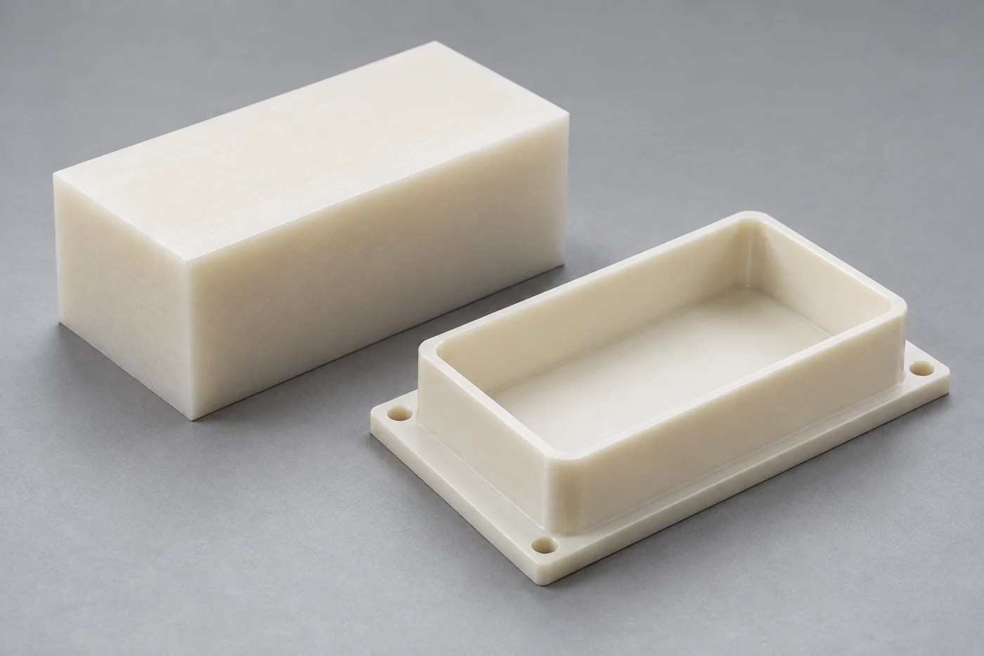
For buyers, the useful question is whether the proposed geometry can be produced, handled and accepted consistently in the specified material. There is no universal minimum wall thickness for every plastic. Wall height, unsupported span, corner geometry, material grade and functional loading all affect the answer. This guide provides a practical review sequence for a machined tray, housing, sleeve or open frame.
What Makes A Plastic Wall Difficult To Machine?
Thinness is a relationship between dimensions and support. A short lip backed by a thick floor can behave very differently from a tall wall of equal thickness. A long open side can flex even when a smaller enclosed pocket remains stable. Review the complete shape rather than approving a thickness value in isolation.
Cutting, clamping and measuring all apply forces. If these forces move a wall, the apparent geometry can change during the operation. Heat and changes in the material's internal stress state can add further movement. These mechanisms can overlap, so a single correction may not resolve every dimensional problem.
Distinguish immediate springback from later dimensional change. Immediate movement after unclamping points toward restraint and elastic deflection as possible contributors. A gradual change deserves a broader review of temperature, moisture, stock history and residual stress. The observations help organize investigation; they do not establish a cause without evidence.
A small prototype quantity also needs an acceptance plan. One attractive sample does not demonstrate that a delicate geometry can survive a different setup, packing method or repeat order. Use the first article to test the proposed manufacturing and inspection assumptions together.
Define The Functional Condition First
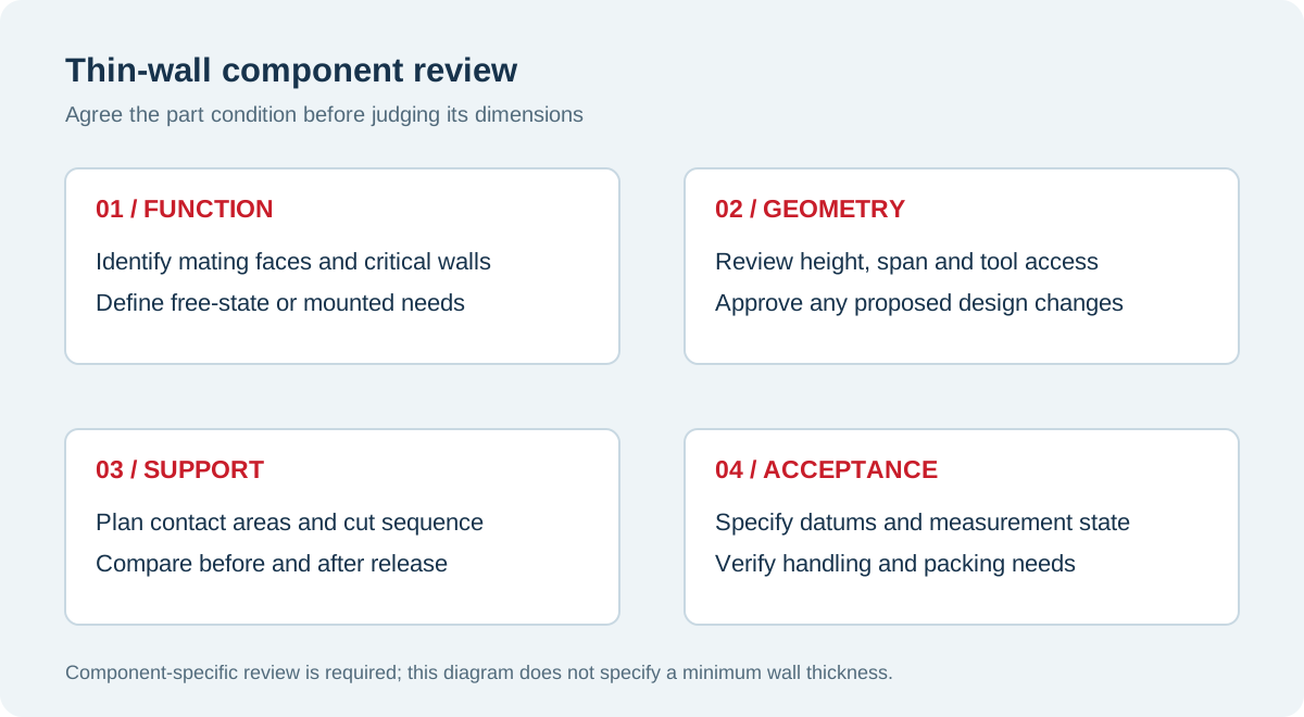
Identify whether the wall locates another part, carries a seal, protects equipment or simply provides a cover. Those jobs require different controls. A sealing land may need a defined relationship to the mounting face. A cosmetic cover may instead need an agreed gap and surface appearance after installation.
State whether a dimension applies in the free state or in a defined restrained condition. If assembly restraint is relevant, describe the support surfaces, fasteners, sequence and agreed loading method. Avoid using an improvised clamp during inspection to make a flexible part appear compliant. The restraint must represent a documented acceptance condition.
Discuss datums before machining. A narrow flexible rim may be a poor reference for inspecting the rest of the component. A substantial mounting face or a set of defined support locations may provide a more useful basis. The design authority should approve the datum scheme and any difference between manufacturing references and functional datums.
Connect these requirements to the quality and inspection discussion. Request evidence that addresses the critical features rather than a generic statement that every dimension has been checked.
Improve Geometry Before Adding Process Complexity
Start by shortening unsupported spans where the design permits. A thicker local section, a return edge or a structural rib can change how a wall responds to cutting and handling forces. Evaluate these changes against the actual function, cleaning needs and available assembly space. Additional material is useful only when it supports the right load path.
Provide realistic internal radii. Very small corners can require smaller tools with longer reach, especially in deep pockets. Review whether the corner is functionally necessary or merely inherited from a metal design. Where another part must fit into the pocket, a local corner relief may deserve discussion instead of demanding an unnecessarily sharp internal corner.
Keep substantial material around mounting holes where possible. A counterbore through a slender flange can leave a fragile section under the fastener head. Ask whether a different fastener location, a load-spreading feature or a revised joint would make the design easier to manufacture and assemble.
Changes require design approval. A machinist should not silently thicken a wall or add a rib to improve yield. Mark permissible alternatives on a review drawing, record the selected revision and use that revision for both quotation and inspection.
| Feature under review | Why it deserves attention | Useful design discussion |
|---|---|---|
| Tall open wall | Limited support near the cutting zone | Reduce height or add permitted support geometry |
| Broad thin floor | Can respond to fixture and measurement forces | Define support locations and free-state acceptance |
| Deep narrow pocket | Restricts tool access and chip clearance | Review depth, radii and access from another face |
| Thin mounting flange | Concentrates clamping and assembly loads | Preserve local thickness or spread the load |
| Slender turned sleeve | Radial restraint can change its shape | Agree bore, outside diameter and inspection state |
Select A Material Grade, Not Just A Familiar Name
The material must satisfy the application before machinability is optimized. Chemical exposure, temperature, electrical requirements and wear can rule out an otherwise convenient candidate. Identify the supplier designation, fillers and stock form. A family label alone leaves too much uncertainty for a demanding thin-wall component.
A reinforced grade can change stiffness and machining behavior, but it also introduces other considerations. Directional properties, tool wear, surface condition and application compatibility need review. Do not substitute a filled grade solely because a sample appears more rigid. Use the identified product's technical information and discuss its suitability with the material supplier.
For moisture-sensitive materials, define the relevant condition at measurement and use. Ensinger's machining FAQ discusses dimensional effects from moisture uptake in polyamides. For a thin nylon feature, the purchasing specification should therefore identify any conditioning requirements rather than leaving incoming inspection to assume an unspecified dry or ambient state.
Compare candidates through the intended function using the engineering plastic selection guide. Choosing a premium polymer does not remove the need for sensible geometry and a reproducible support arrangement.
Plan Workholding Around Support And Release
A fixture must resist the machining loads without imposing unacceptable distortion. More clamp force is not automatically better. Broad contact surfaces and support near the operation can be more useful than strong localized restraint. Keep tool clearance, chip escape and protection of finished faces in the same review.
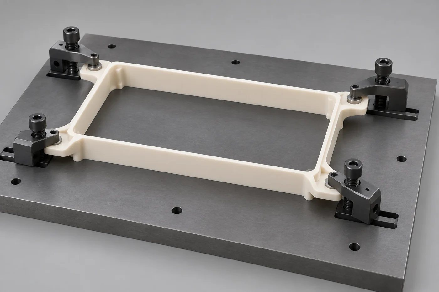
For an open tray, consider where clamps can bear on substantial material while the surrounding plate supports the floor. For a frame, evaluate whether temporary stock or approved sacrificial tabs can support the shape until later operations. These are possible process approaches, not instructions that fit every part.
The fixture illustration shows an open polymer frame resting on a broad support plate, with clamps positioned on substantial external tabs. Its purpose is to illustrate the support discussion. Actual tab dimensions, contact forces and cutting clearances need a component-specific plan and trial.
Vacuum workholding may be suitable for some plate geometries, but suitability depends on available sealing area, leakage paths and cutting loads. Through holes and pocket breakouts can change the holding condition during a program. Request a process review rather than specifying vacuum as a universal solution for every thin floor.
Release and recheck a representative feature during first-article development. Record whether its position changes when restraint is removed. The objective is to understand the relationship between the setup and the finished geometry, not to use fixture pressure as an undocumented adjustment to the final dimensions.
Sequence Material Removal To Preserve Control
Leave enough material for useful support during early operations, then approach the finished geometry through a planned sequence. The appropriate allowances depend on the stock and part. There is no single roughing allowance or number of passes that guarantees a stable result across all engineering plastics.
Discuss how opposing faces and deep pockets will be approached. Removing a large volume from one side may expose movement that was not apparent in the original blank. The plastic machining warpage guide explains why stock removal and restraint should be considered together.
Sharp tools, clearance and chip evacuation remain essential. Mitsubishi Chemical Group's machinist toolkit emphasizes controlling heat and removing swarf in plastic machining. Apply its guidance to the identified stock product and operation rather than transferring a metal cutting recipe unchanged.
Do not assume an extremely light pass always produces the best result. Rubbing, chip formation, tool geometry and unsupported wall movement must be evaluated together. The process should demonstrate a clean cut and acceptable released geometry. This article intentionally provides no universal speed or feed table for an unspecified machine, tool and polymer.
If intermediate stress relief is proposed, review its compatibility with the grade and geometry before adding it to the route. The annealing guide outlines the information needed. A heat treatment is not a substitute for correcting an unsuitable fixture or impossible acceptance condition.
Inspect Without Forcing The Part Into Shape
Inspection equipment can influence a flexible feature. A contact instrument with excessive force may move the wall it is intended to measure. Define the support and measurement approach for critical dimensions. Where noncontact equipment is proposed, confirm that the chosen method can resolve the actual surface, edges and required feature relationship.
Agree temperature and conditioning requirements in advance. Record the relevant state rather than taking measurements immediately after machining and treating them as final. If the drawing specifies a restrained inspection, identify the fixture and method so another inspector can reproduce the result.
Compare measurements before and after release when investigating a discrepancy. Repeating the same measurement under the same undocumented force can produce consistent numbers without revealing the problem. The useful evidence is how the geometry responds to controlled changes in support, restraint and time.
For a delicate rim or thin floor, packaging is also part of acceptance planning. Avoid arrangements that impose uncontrolled bending loads during transit. Define where the part can be supported and whether contact with a finished face is permitted. Handling instructions should follow the drawing's functional priorities.
A Hypothetical Housing Review
Consider a proposed machined housing with a deep central pocket, a broad floor and a narrow top rim. This is a design example, not a TOPS customer case. The original request applies the same tight dimensional requirement to every wall, while leaving the inspection state unspecified.
A useful review starts with the mating surfaces. The buyer identifies the mounting base and a connector opening as critical. The design team can then consider wider allowances on nonfunctional exterior faces, a larger internal corner radius and substantial clamp locations that remain available until finishing.
The parties also agree how the housing will be supported during inspection and which dimensions apply after release. This does not guarantee production success. It creates a meaningful first-article trial, because the supplier and buyer are testing the same acceptance conditions instead of comparing unrelated measurements.
What To Include In Your RFQ
Send the current drawing and model, quantity, material designation and revision. Mark the critical walls, functional datums and surfaces that must remain free from clamp marks. Identify any dimensions that apply in assembly, together with the approved restraint or mounting details.
Explain whether design changes are possible and who can approve them. A supplier can offer more useful feedback when a radius, wall height or clamp tab is open to review. If the geometry is fixed, say so before a quotation assumes a simpler alternative.
Request the first-article evidence, packaging expectations and repeat-order controls you actually need. For custom machined plastic parts, production cost includes setup and verification as well as cutting time. Compare quotations against the same drawing revision and acceptance scope.
Frequently Asked Questions
What Is The Minimum Wall Thickness For CNC Machined Plastic?
There is no universal value. The feasible thickness depends on wall height, span, material, access, support and tolerances. Submit the complete geometry and functional requirements for review instead of approving a design from thickness alone.
Can A Thin Wall Be Accurate While Clamped But Fail After Release?
Yes. Restraint can hold a flexible feature in a different shape. Specify whether acceptance is free-state or restrained, and document any fixture used for the latter. First-article measurements should address the required condition.
Should Every Thin Plastic Part Be Annealed?
No. The decision depends on the stock, material guidance and observed or anticipated movement. Any proposed cycle needs review. Annealing cannot compensate for an unsuitable datum scheme or excessive fixture distortion.
Is A Tighter Tolerance The Best Way To Improve Assembly Fit?
Start with functional datums, operating conditions and the mating parts. A tighter number does not explain which state to measure. An appropriate tolerance with a clear inspection method is more useful than an ambiguous requirement.
Discuss Your Thin-Wall Component
Send TOPS Plastics your drawing for review. Include the material, quantity and critical acceptance conditions. Identify where geometry changes are permitted so the discussion can address wall support, machining access and inspection before a production commitment.