
Choose acrylic or polycarbonate by the finished component’s visual, mechanical and environmental requirements. Both material families can provide transparent machined parts, but transparency alone does not establish suitability. The useful comparison identifies the actual stock product, the loads and exposures it will encounter, and the evidence needed to accept the finished component.
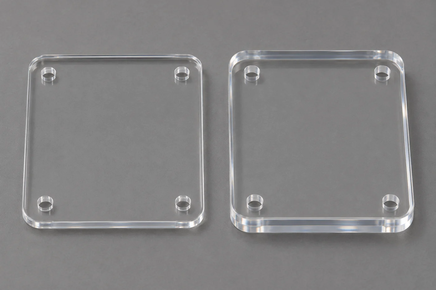
For a buyer sourcing a clear cover, viewing component, enclosure detail or equipment panel, the drawing should explain what clear means in use. A surface that looks attractive on a sample may not meet an optical task, and a transparent sheet is not automatically a qualified protective guard. This guide sets out the questions to resolve before ordering.
Identify The Visual Function First
Start with what the user must see through the component. General visibility, reading a display and performing an optical measurement are different jobs. State the viewing area and relevant conditions rather than relying on a broad note such as crystal clear.
A component may need transparency only through a central region, while its mounting flange is hidden. Mark that distinction. It can help the supplier focus handling and finishing controls on the surfaces that matter without imposing an unexplained cosmetic requirement everywhere.
Describe any permitted marks, edge appearance or haze through an agreed inspection approach. If a reference sample is used, define its role and how comparisons are made. An unrecorded visual preference can become difficult to reproduce across inspectors or repeat orders.
Use the surface-finish guide to organize the discussion. Surface texture, appearance and optical performance need their own acceptance basis rather than being treated as interchangeable descriptions.
Distinguish The Material Families And Products
Acrylic commonly refers to polymethyl methacrylate, or PMMA. Polycarbonate is commonly abbreviated PC. These are different polymers, and their stock products can also differ in grade, manufacturing route, additives and surface treatment. Identify the product proposed for the actual order.
SyBridge’s acrylic and polycarbonate machining comparison describes their use in transparent machined components and distinguishes polycarbonate’s impact-related characteristics. Treat that as a starting point for selection. It does not establish a safety rating or service guarantee for every product or component geometry.
Ask whether the stock has a coating, tint or other treatment relevant to the application. A coated sheet and an uncoated stock shape may require different handling and machining discussions. Confirm how any treatment relates to the faces being cut or finished.
Record the approved designation in the drawing or purchasing documents. The material traceability guide explains why appearance cannot establish the supplied grade or its supporting evidence. Two clear parts can look similar while representing different products.
Separate Impact Needs From General Durability
If impact is relevant, describe the actual requirement. Object type, energy, support, temperature and geometry can influence the evaluation. A general statement that polycarbonate is tough does not specify whether a finished panel will perform a protective function in a machine.
For a protective application, the responsible design or safety team should define the required evaluation and applicable evidence. Do not transfer a material data-sheet result directly into an unrestricted claim about the assembled guard. Mounting and surrounding structure form part of the system.
For a simple viewing cover, the dominant concern may instead be handling damage or occasional contact. That can lead to a different acceptance plan. Clarify the consequence of failure so the material decision is proportionate to the actual function.
Keep appearance and mechanical behavior separate in the comparison. A candidate can meet a visual requirement while leaving the impact question unresolved. The approval record should show which requirements have evidence and which still need evaluation.
Review Geometry And Machining Access
Both candidates require a manufacturing review of the drawing. Hole locations, remaining sections, deep pockets and sharp internal corners can affect how the component is held and machined. A material’s suitability for CNC processing does not establish every geometry as practical.
Ensinger’s polycarbonate machining information describes milling and turning as routes for PC components. Use that information to support a product-specific discussion rather than assuming a process established for PMMA transfers unchanged to PC.
The pocket-design guide explains why internal radii and cavity depth deserve review together. Where design changes are possible, ask the supplier to identify alternatives and their functional consequences before approving a revision.
Review thin areas around holes and edges. A mounting feature close to an unsupported corner can deserve more attention than a hole in a broad section. The complete geometry and assembly matter more than a universal minimum-thickness rule.
Treat Mounting As Part Of The Design
Describe how the clear component is attached and supported. Fasteners can introduce local loads, while the surrounding structure can constrain movement. A material comparison that ignores the mounting arrangement leaves an important part of the component’s behavior unreviewed.
Discuss hole clearance, contact areas and any requirement to accommodate movement. The responsible engineer should determine the joint details. Do not use a single generic screw-torque recommendation for an unspecified plastic product, thickness and assembly.
The mounting illustration shows a transparent panel beside separate hardware. It illustrates a joint-review discussion. It does not prescribe washer dimensions, screw loading or an approved fastening method for a real protective or optical component.
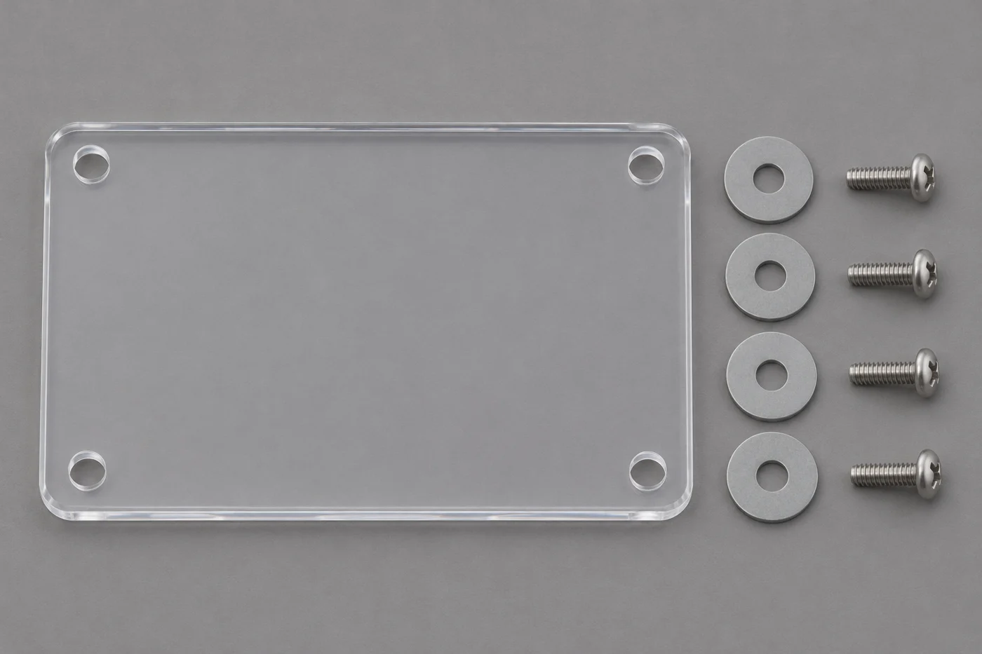
For a broad panel or thin frame, define whether inspection applies in the free state or a documented restrained condition. The thin-wall machining guide discusses why support and restraint can influence the apparent shape.
Consider Temperature And Mating Materials
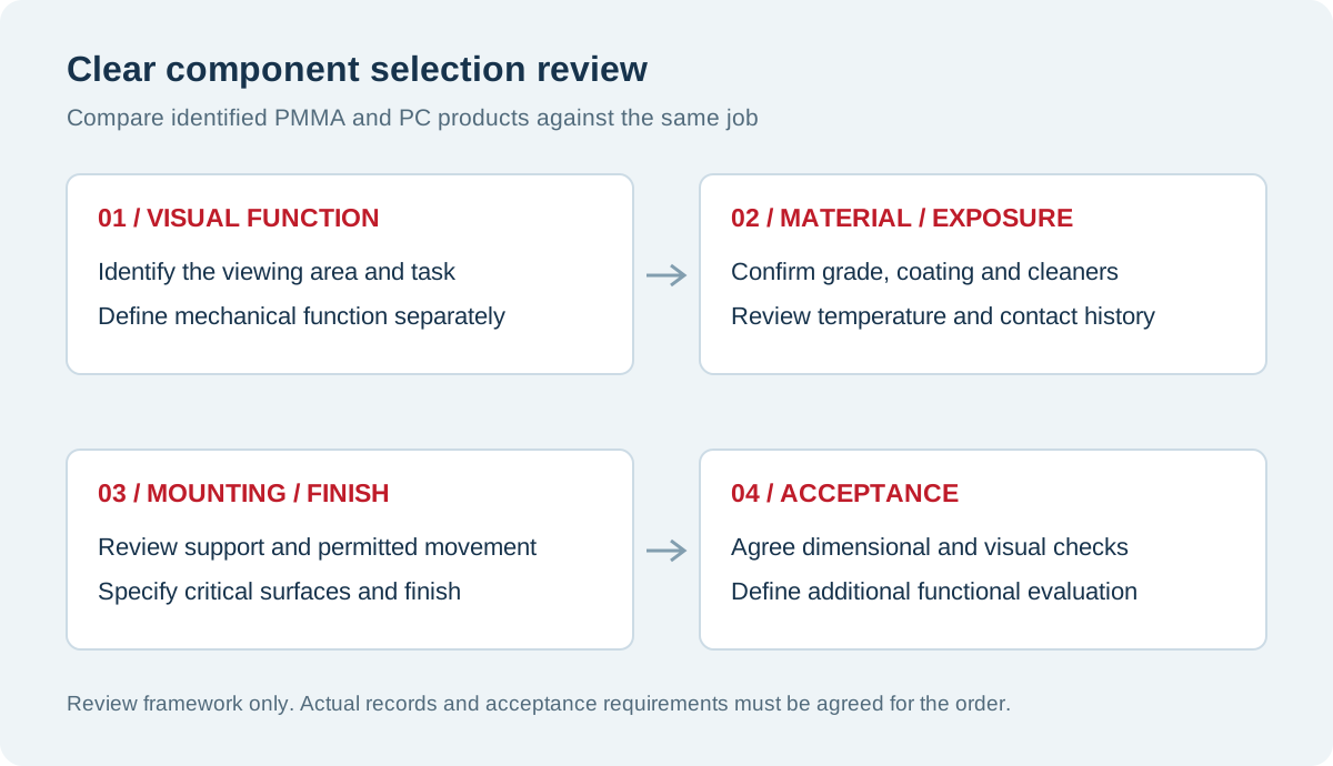
Specify normal operating temperature and relevant changes during startup, cleaning or storage. The clear part may expand differently from its surrounding structure. The design should account for the assembly rather than checking only the polymer’s initial room-temperature dimensions.
The thermal expansion article provides a framework for reviewing movement and fit. Use grade-specific information where a calculation or evaluation is required. Do not assume every PC or PMMA product shares one expansion value.
A close-fitting recess can create a different situation from a freely supported panel. Identify where movement is permitted and where the component locates another feature. Those conditions help the supplier understand which dimensions and mounting relationships are critical.
Define the measurement state for acceptance. A dimensional comparison is more useful when supplier and buyer use compatible temperature, support and timing conditions. An unexplained tight tolerance does not resolve differences between those states.
| Selection question | Information to establish | Useful acceptance discussion |
|---|---|---|
| Visibility | Viewing area, task and conditions | Define appearance or optical evidence |
| Mechanical role | Contact, handling and any protective function | Establish the required component evaluation |
| Stock identity | Grade, form, coating and source | Confirm the actual approved product |
| Mounting | Support, fasteners and permitted movement | Review the assembled load path |
| Exposure | Process media, cleaners and temperature | Check the complete material-contact route |
| Finish | Critical faces, edges and permitted marks | Agree a reproducible inspection method |
Review Chemicals And Cleaning Agents
List the actual substances the part will encounter, including cleaning and maintenance products. Concentration, temperature, duration and loading condition belong in the review. A broad chemical-resistance description does not establish compatibility with every cleaner used around the equipment.
The chemical resistance guide explains why those details matter. Ask for guidance relevant to the exact stock product. If information does not cover the proposed exposure, identify what further evaluation is needed before approving the material.
Machining fluids and post-machining cleaning also deserve review. Mitsubishi Chemical Group’s machining toolkit discusses the risk of stress cracking from some fluid combinations in certain amorphous plastics. Keep that guidance within its stated scope and verify the proposed material-fluid route.
The coolant article provides a structured discussion of processing exposure. Do not prescribe a universal solvent or cleaning cycle for every transparent part. The required residue removal and the material’s compatibility need to be considered together.
Plan Finishing Before The Final Dimensions
A machined clear surface can require additional finishing to achieve an agreed appearance. Identify which faces need that work and what result is required. Do not assume the word polished describes a single process suitable for both materials and every feature.
Review whether finishing can affect dimensions, edges or the material state. If a functional face or close-fitting feature is involved, connect the finishing route to the inspection plan. Acceptance should describe the delivered condition rather than only the shape before finishing.
Use the plastic polishing page to begin a project-specific inquiry. Ask the supplier to identify the proposed approach, limitations and any surface that cannot receive the same treatment as an open face.
Keep the first article representative. A flat polished sample may help communicate appearance, but it cannot establish every result for a pocketed cover with small holes and constrained edges. The geometry used for approval should reflect the important production features.
Protect Surfaces Through Handling And Shipment
Identify permitted contact locations and surfaces that require protection. The relevant controls extend beyond cutting to deburring, cleaning, inspection, packaging and receiving. A clear component can be damaged after machining even when the cutting operation itself was satisfactory.
Agree how protective materials are used and removed where that affects acceptance. Do not assume every film or packaging contact is compatible with every coating or finish. The proposed handling route should be suitable for the identified product and critical faces.
At receipt, keep the component associated with its identity and inspection records. If damage is observed, document the condition and packaging before altering it. That evidence helps distinguish a surface-acceptance issue from a later handling event.
Specify storage or installation instructions where the project requires them. A delivery requirement should reflect the buyer’s actual workflow, including any inspection step before assembly, rather than applying only to an unopened package.
Make First-Article Checks Match The Requirement
Agree dimensional and visual checks before the first article is made. Identify critical faces, viewing conditions and mounting relationships. If the application requires an optical or mechanical test, define its scope with the responsible technical team.
The first-article inspection guide explains how measurement state and support make results comparable. A report with correct dimensions can still leave the visual or functional requirement unanswered if those checks were never defined.
Record what the approval covers. A successful sample from one grade or finishing route should not silently authorize a different stock product. Changes affecting material, surface treatment or mounting need review against the original acceptance basis.
A limited evaluation does not prove every possible service outcome. Describe differences between the trial and the intended application, especially where impact, exposure or operating duration differs. This lets reviewers use the evidence without extending it beyond its scope.
A Hypothetical Display-Cover Decision
Imagine a buyer selecting a transparent machined cover for an equipment display. The initial drawing says clear plastic and provides overall dimensions, but it does not identify the viewing area, cleaner or mounting arrangement. This is a hypothetical example, not a TOPS customer case.
The review establishes the visual task, expected contact and cleaning conditions. The team then compares identified PMMA and PC products and checks the proposed finishing and support. Any protective function is evaluated separately under a defined requirement.
The approved result becomes a material designation and acceptance plan tied to the drawing revision. Future orders can then use that controlled reference instead of relying on the appearance of an old sample or a broad transparent-material label.
What To Include In Your RFQ
Send the current drawing and model, quantity and proposed material designation. Mark the viewing area, critical mounting features and surfaces needing additional finish. Describe the use environment and cleaning contacts that influence selection.
State any mechanical or optical evaluation required for release. Ask the supplier to identify limitations and proposed exceptions before production. Compare quotations against the same stock, finish, inspection and packaging scope so the commercial decision represents the accepted component.
Frequently Asked Questions
Are Acrylic And Polycarbonate Interchangeable Because Both Are Clear?
No. Compare identified grades against the actual visual, mechanical, chemical and temperature requirements. Transparency alone does not establish equivalence. Any substitution needs approval against the component specification.
Does A Polycarbonate Sheet Automatically Make A Qualified Safety Guard?
No. The assembled component, mounting and required performance need their own evaluation. Material information supports the review but does not automatically qualify every finished guard design.
Will Polishing Produce The Same Result On Every Clear Plastic?
No. The material, geometry, process and acceptance requirement matter. Define the critical faces and intended result, then review a representative first article where needed.
Can Appearance Be Accepted Without A Defined Viewing Method?
It can create disagreement. Agree the relevant area, conditions and permitted marks so supplier and receiving inspection evaluate comparable results. Use additional optical evidence when the application requires it.
Discuss Your Transparent Component
Send TOPS Plastics your drawing and viewing requirements. Include quantity, material candidates, mounting details and critical surfaces. Those details support a practical comparison of machining, finishing and acceptance before production.