
CNC plastic manifold design starts with the fluid circuit, not the outside shape. Define connections, isolated passages, port interfaces and sealing requirements together. Then review material, machining access and acceptance evidence. A complete drawing package helps you compare quotations without confusing dimensional manufacture with validated fluid-system performance.
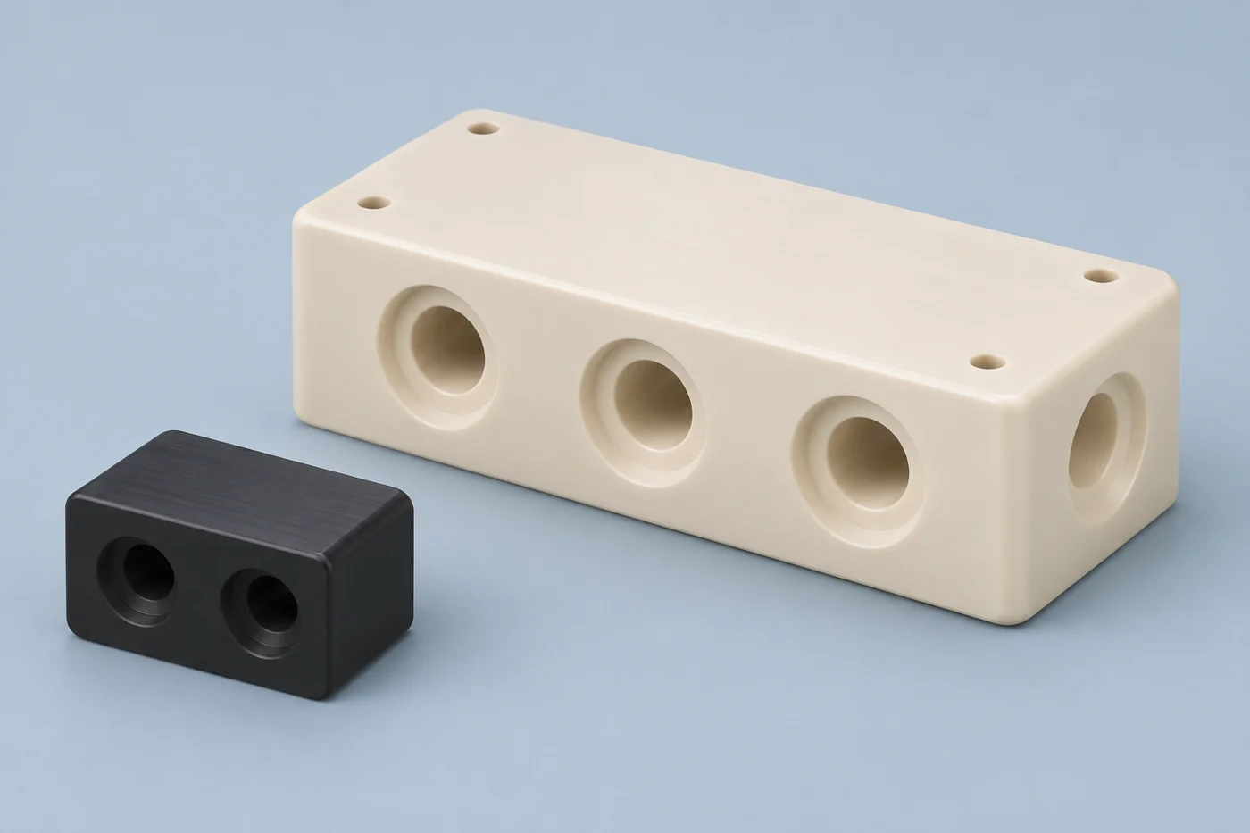
What Should You Define Before Modeling The Block?
Define what each port connects to and which circuits must remain isolated before choosing the block layout.
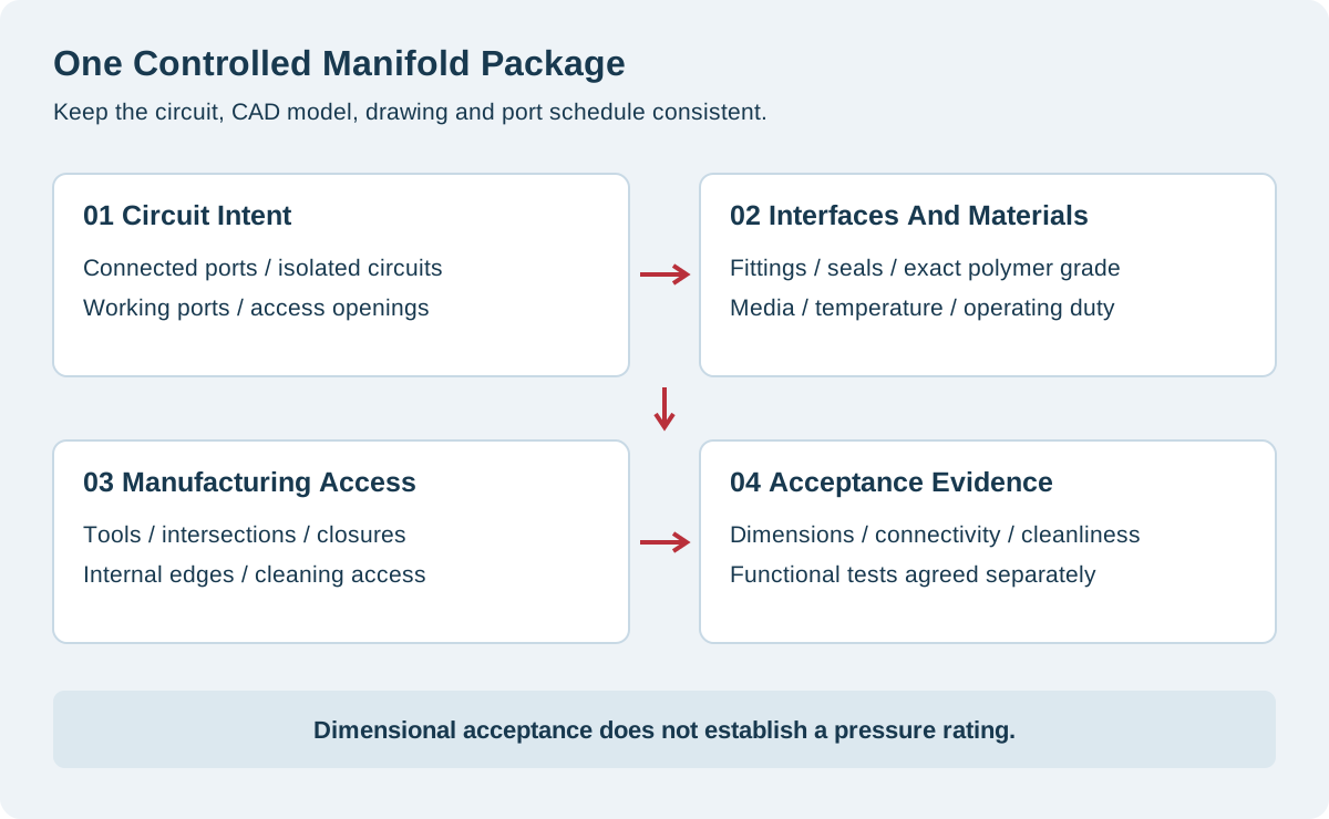
Create a circuit map with unique port identifiers. Separate working connections from drilling-access openings and mounting holes. Add the intended flow direction where relevant, without assuming that an arrow proves balanced distribution.
For an illustrative distribution circuit, label one inlet P1 and two outlets P2 and P3. State explicitly that those ports communicate. If a second circuit exists, identify its ports and required isolation. This example communicates design intent, not an approved channel arrangement.
Record the medium, operating temperature, pressure or vacuum, and expected flow. Include startup, shutdown and cleaning conditions. Mark unknown inputs instead of allowing an estimate to become an unintended requirement.
Keep the circuit map beside the model throughout review. An attractive exterior rendering cannot communicate hidden connections reliably. Section views and a port schedule provide a clearer basis for manufacturing discussions.
Check Connections In Both Directions
For the illustrative circuit, check P1 against P2 and P3 individually. Then list any ports that must not communicate. This review catches a different error from merely counting visible openings.
Use the same identifiers in the model sections and inspection record. If an opening exists only for machining access, mark its closure requirement separately. Do not describe it as an available equipment connection by accident.
During revision review, compare the connection list before and after the change. A deeper passage can affect a neighboring circuit even when the port face remains unchanged. This is a design-review example, not evidence that a particular block is suitable for service.
What Belongs In A Manifold Port Schedule?
A manifold port schedule should identify the complete connection and its relationship to the fluid circuit.
Do not specify a port only by its nominal size. Record the thread or connection standard, size, pitch where applicable, depth and sealing location. Include the mating fitting designation and supplier drawing when available.
The Swagelok thread identification guide distinguishes thread taper, diameter, pitch and end connection. Identifying a thread does not establish the suitability of that fitting in your polymer body.
| Schedule Field | What You Should Record | Why It Matters |
|---|---|---|
| Port identifier | Unique label matching circuit and drawing | Prevents ambiguous inspection and assembly |
| Connection definition | Standard, size, pitch and mating fitting | Separates similar-looking interfaces |
| Sealing location | Thread, face, radial gland or specified seat | Identifies the functional surfaces |
| Position and direction | Datum-based location and axis | Controls assembly alignment |
| Depth and clearance | Functional engagement and internal boundary | Protects neighboring passages |
| Acceptance evidence | Required dimensions and agreed checks | Makes quotation scope comparable |
Use the actual fitting geometry when checking assembly space. Include wrench access, tube routing and the installation sequence. A port may fit within the block while remaining inaccessible after adjacent fittings are installed.
If you receive a sample fitting without documentation, request positive identification. Do not freeze the manifold drawing around a guessed thread. Record any identification uncertainty before ordering tooling or stock.
How Do You Separate Retention From Sealing?
Identify which feature retains the fitting and which surface or element creates the fluid seal.
A thread description alone does not specify every sealing interface. Some connections use tapered threads; others use separate seals with retaining threads. Follow the selected fitting's approved interface and installation requirements.
Do not apply a metal assembly's torque assumptions to an arbitrary plastic port. Review the fitting, remaining material and service conditions together. Ask the responsible designer to resolve installation limits before manufacturing approval.
For O-ring connections, identify whether compression is axial or radial. The Parker O-Ring Handbook explains these arrangements and the relationship between gland and compound selection.
Specify the selected seal and its supporting geometry. Include groove dimensions, tolerances, relevant surface requirements and the mating component. Avoid copying a generic groove into the model before selecting the complete sealing arrangement.
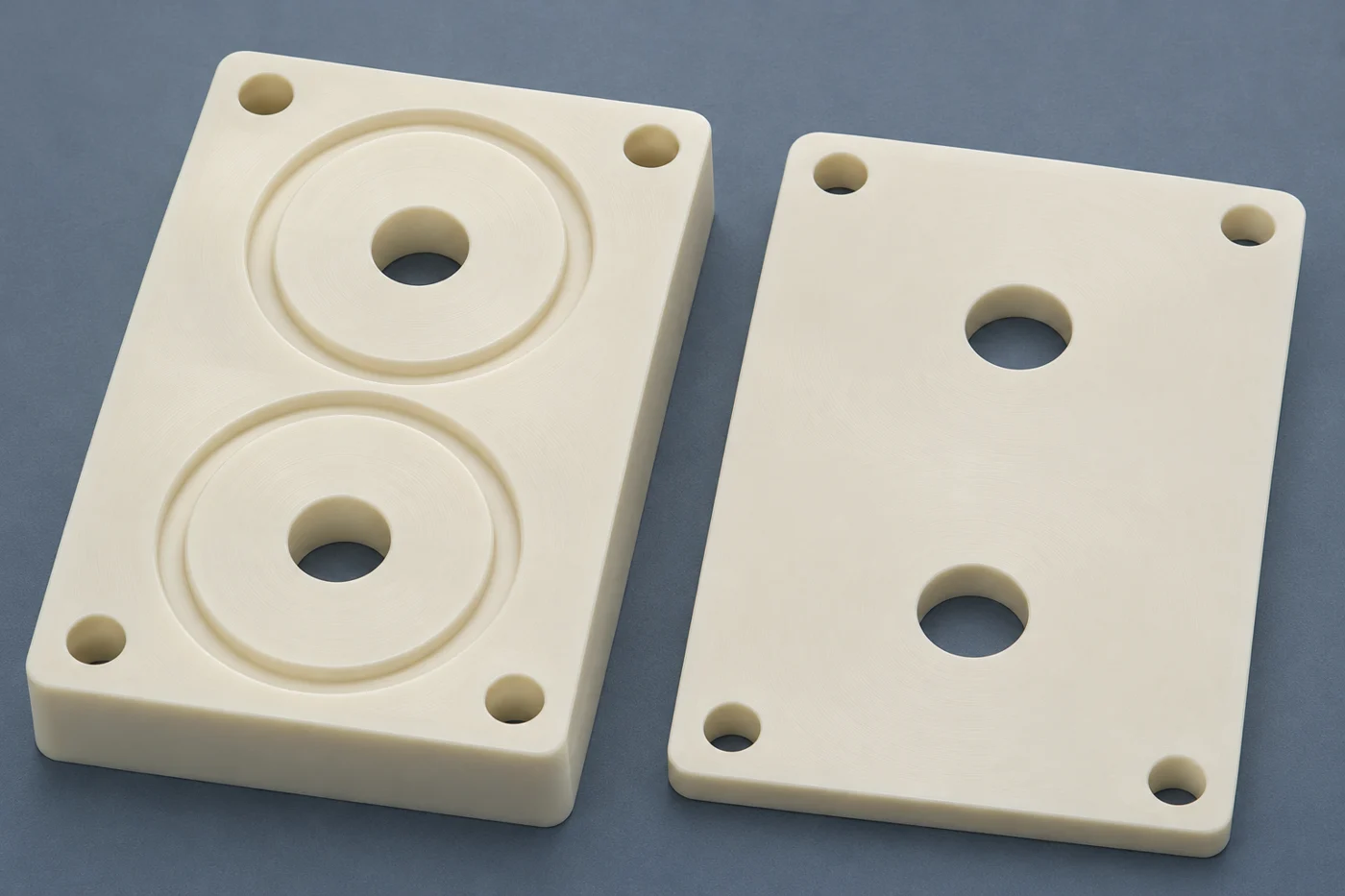
The sealing illustration shows separated plates and conceptual circular glands. It does not provide seal dimensions, bolt loading or a pressure rating. Use it to distinguish a machined feature from an approved sealing design.
How Should You Review The Wetted Materials?
Review every wetted component against the complete process and cleaning cycle, not only the manifold body.
Identify the purchased polymer grade and required documentation. Record the fluid or mixture, concentration, temperature and exposure duration. Add seal compounds, plug materials, fitting materials and any proposed assembly chemicals.
Ensinger's chemical-resistance training overview identifies temperature, concentration, exposure time and mechanical stress as relevant factors. A room-temperature compatibility entry cannot answer every assembled-service question.
Build a short compatibility record for your project. List each wetted item, its exact designation and the evidence supporting its use. Identify any remaining validation work separately from the manufacturing drawing.
If transparency is required, specify its purpose. Viewing bubbles, checking assembly and measuring optical transmission are different requirements. Choose the necessary viewing faces and acceptance method rather than asking for an undefined clear finish.
Use our chemical resistance guide for a broader selection checklist. Keep material compatibility separate from pressure capability, cleanliness and regulatory documentation. One favorable property does not establish the others.
How Does Machining Access Change The Channel Layout?
Channel layout must provide a practical route for cutting tools and a defined closure for every access opening.
Review the block from each machining direction. Identify where a drill enters, where it stops and which passages it intersects. Include section views that expose the intended connections and neighboring boundaries.
The MCG machining toolkit discusses drilling heat and chip removal in engineering plastics. These concerns belong in the manufacturing review, especially for long internal passages. They do not establish one universal drilling limit.
Discuss access before locking the external dimensions. A small relocation may simplify machining and inspection. Conversely, an inaccessible intersection can require a different channel layout or assembly concept.
Treat cross-drill closures as designed interfaces. Identify the plug, retention, sealing method and final inspection. An access hole does not disappear from the functional specification merely because it is absent from the normal flow diagram.
Review the remaining material around ports, grooves and mounting features. There is no single minimum wall dimension for every polymer manifold. Geometry, material, temperature, loading and fitting installation require project-specific assessment.
How Can You Make Internal Passages Inspectable?
Design the passages so you can obtain credible evidence of the required connections, surfaces and cleanliness.
Separate three questions during review. Do the intended ports communicate? Do isolated circuits remain separate? Are internal features acceptable for the specified use? A single observation may not answer all three.
Identify hidden intersections and access restrictions on the drawing package. Discuss the available inspection method before production. If a feature cannot be evaluated adequately, consider changing access or revising the design.
Use our plastic deburring guide when defining edge requirements. Specify which internal edges matter and what acceptance evidence you require. An external cosmetic check cannot verify every hidden intersection.
Define cleaning requirements in measurable project terms. State the permitted cleaning media, any residue or particle criteria, and the agreed verification method. Do not assume that visually clear liquid proves validated cleanliness.
Include drying, temporary port protection and packaging where the application needs them. Agree which materials may contact finished passages. Keep any special handling requirement visible in both the quotation and purchase specification.
Which Dimensions Deserve Functional Tolerances?
Apply functional tolerances to the relationships that control connection, sealing, mounting and circuit boundaries.
Choose datums that represent how the manifold locates in the assembly. Relate port axes and mounting features to those datums. Avoid locating every feature from a different convenient model edge.
| Feature Group | Functional Question | Drawing Review |
|---|---|---|
| Port axes | Will fittings align with the mating equipment? | Position, direction and reference datums |
| Sealing faces | Will the specified seal contact its support? | Flatness, finish and mating geometry |
| Glands | Does the feature match the selected seal design? | Width, depth, corners and tolerances |
| Internal intersections | Do passages connect without unintended breakthrough? | Sections, depths and boundary locations |
| Mounting features | Can the block locate without assembly interference? | Hole pattern and installed relationships |
Specify the inspection condition for critical dimensions. Identify whether the part is free, supported or evaluated in an agreed fixture. Measurement conditions matter when the component can deform under support or contact forces.
Avoid applying the tightest tolerance to every outside surface. Connect each demanding requirement to a functional reason and inspection method. This helps the supplier quote the work you actually need.
What Should The Manufacturing Review Cover?
The manufacturing review should connect the approved circuit and interfaces to an agreed process and inspection plan.
Our custom plastic manifold service covers drawing-based ports, internal passages, sealing features and mounting geometry. Milling, drilling, tapping and related operations are reviewed against the specific design. Special functional tests require a separately agreed scope.
Use a review sequence such as this:
- Confirm the model, drawing revision, circuit map and port schedule.
- Identify the exact stock grade and required traceability documents.
- Review machining directions, tool access, closures and remaining material.
- Agree critical dimensions, internal checks and edge acceptance.
- Define cleaning, handling and packaging requirements.
- Separate prototype evaluation from repeat-production acceptance.
Resolve discrepancies between documents before machining begins. If the model and port schedule disagree, record the decision and revise the controlled package. Do not rely on an informal interpretation that later orders cannot reproduce.
How Do You Define Testing Without Assuming A Rating?
Define functional acceptance separately from dimensional inspection and assign responsibility for each test.
A correctly measured bore does not establish a pressure rating. A leak check at one condition does not establish lifetime performance. Keep design qualification, production acceptance and maintenance checks distinct.
Ask your responsible engineer to define the required test specification. It should identify the assembly configuration, medium, conditions, duration and acceptance criteria. Confirm provider capability and the required report before including testing in the order.
Specify which ports are connected, closed or monitored during each check. Otherwise, a reported pass may not demonstrate the isolation or external leakage requirement you intended. Include fitting and closure configurations in the record.
Do not invent test pressures or transfer them from unrelated metal fittings. Higher pressure is not automatically a better acceptance test. Testing needs an appropriate procedure and controlled arrangement for the actual assembly.
How Do You Compare Cost And Control Revisions?
Compare quotations against the same drawing package, material identity and acceptance scope.
Review stock size, machining directions, difficult passages, closures, sealing features and inspection effort. Include cleaning, documentation and packaging. A low piece price may omit requirements that another quotation includes.
Separate development quantities from expected repeat orders. State which features remain open for review and which interfaces are fixed. Request proposed design changes explicitly, rather than accepting an undocumented substitute.
When a prototype changes, update the model, drawing, circuit map and port schedule together. Review whether the change affects previously accepted evidence. A moved port can alter more than the outside appearance.
For a drawing-based quotation, contact us with CAD, drawings, grade, quantities, port schedule and operating conditions. Include sealing, inspection and testing requirements. Agree confidential-file handling before sharing sensitive designs.
Frequently Asked Questions
Use these answers to close common drawing-package gaps before requesting a manifold quotation.
Is A 3D Model Enough For A Manifold Quote?
It supports geometry review, but hidden circuit intent and acceptance requirements may remain unclear. Include sections, a circuit map and port schedule.
Can Similar-Looking Threads Be Substituted?
Do not assume interchangeability. Confirm the complete thread and end connection, mating fitting and sealing arrangement before approving a substitution.
Does Every Threaded Port Seal On Its Threads?
No. Some connections use a separate seal. Identify the sealing location and follow the selected interface requirements.
Can I Copy An O-Ring Groove From Another Part?
Only after checking the complete seal design and operating conditions. A matching appearance does not establish correct gland dimensions or support.
Do Transparent Blocks Prove The Channels Are Clean?
No. Visual access can help observation, but it cannot replace specified cleanliness criteria and an appropriate verification method.
Does Dimensional Inspection Establish Pressure Capability?
No. It verifies specified geometry. Application qualification and any production leak or pressure acceptance require their own defined evidence.
What If An Internal Intersection Cannot Be Inspected?
Resolve the evidence gap before approval. Review additional access, an alternative method or a revised layout with the supplier and designer.
Should I Request The Lowest Price Before Design Review?
Request comparable scope first. Material, closures, inspection, cleaning and documentation must be clear before price differences become meaningful.
Release A Complete Manifold Package
Good CNC plastic manifold design connects the circuit, ports, seals and acceptance plan. Resolve hidden connections and interface uncertainty before release. Compare manufacturing quotations against the same controlled package, then validate the assembled system against its intended duty.