
Choosing tapped threads vs threaded inserts in plastic parts starts with joint requirements. Direct threads may suit simpler assemblies. Inserts deserve review when repeated servicing or demanding joint conditions make them useful. Your grade, geometry, installation process and validation plan determine the final choice.
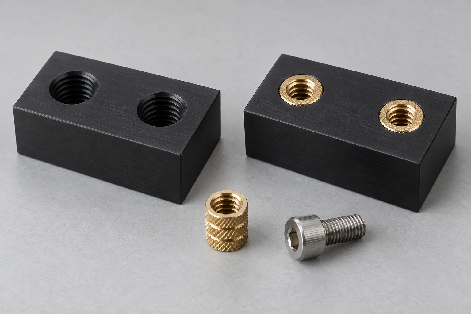
Should You Tap Plastic Directly Or Use An Insert?
Choose the joint around its loads and service life, rather than assuming every plastic hole needs a metal insert.
Direct tapping creates the female thread in the polymer. An insert provides a separate threaded component anchored in the plastic.
Mitsubishi Chemical Group’s machining toolkit says inserts are unnecessary for many engineering-plastic applications. It recommends considering them for strong vibration or repeated clamping and unclamping.
Treat that guidance as a starting point. A removable inspection cover and a permanently assembled spacer have different service requirements.
You still need to establish acceptable assembly torque, retention and environmental exposure for the actual joint.
How Do The Two Options Compare?
Direct threads simplify the component list, while inserts introduce a separate hardware and installation specification.
Use this comparison to identify questions for your design review. Neither column guarantees successful performance.
| Decision | Directly Tapped Plastic | Threaded Insert |
|---|---|---|
| Thread interface | Screw engages the polymer thread | Screw engages the insert thread |
| Manufacturing scope | Machine and inspect the specified thread | Prepare the receiving hole, install hardware and inspect |
| Service requirement | Validate repeated assembly if required | Review retention and repeat-use requirements |
| Drawing information | Thread designation, usable depth and location | Insert part number, receiving geometry and installed position |
| Potential failure to investigate | Damaged threads or inadequate engagement | Insert rotation, pull-out or surrounding plastic damage |
| Cost comparison | Consider machining, inspection and rework | Include hardware, installation, checks and rejected assemblies |
This table is a procurement checklist. Final acceptance must reflect your particular material and assembly.
When Can Directly Tapped Threads Be A Practical Choice?
Direct threads merit evaluation when the assembly requirements can be met without additional hardware.
Start with the exact polymer grade and the available geometry. Avoid specifying only a family name when fillers or modifications matter.
For Delrin / POM machining, identify the required grade before agreeing on threaded features.
Ask how the thread will be produced and inspected. The MCG toolkit highlights pilot-hole sizing and suitable tapping methods.
A thread that accepts the screw does not automatically establish adequate retention. Validate the usable engagement and assembly conditions separately.
If customers will repeatedly open the assembly, include that requirement in the review. Do not assess the joint using one successful tightening.
When Should You Evaluate Threaded Inserts?
Evaluate inserts when your joint requirements justify separate hardware and a controlled installation operation.
SPIROL’s insert design guide distinguishes torque resistance from axial pull-out resistance. Its selection guidance also connects insert choice with the installation method.
These are separate design questions. Ask whether the insert rotates during tightening and whether it resists the specified axial loading.
Then consider the surrounding plastic and mating component. A metal female thread does not validate the complete assembly by itself.
You should also review contamination, electrical isolation and material-compatibility requirements where relevant. Adding metal can change the component specification beyond its thread.
Do not replace an approved direct thread with an insert without checking the drawing and customer requirements.
How Do Material And Environment Change The Decision?
Review the exact plastic grade and operating conditions before transferring a successful thread design to another component.
For example, a dry inspection fixture and a washdown enclosure have different exposure histories. Ask which state your acceptance measurements represent.
For Nylon machining, include relevant moisture conditions in the specification. Our Nylon vs Delrin comparison explains why that distinction matters.
For filled grades, identify the filler and supplier designation. Do not treat an unfilled material’s installation trial as approval for a reinforced version.
SPIROL’s performance guidance identifies material composition, hole consistency, installation and mating-component support as performance variables.
That makes a copied catalogue result insufficient for approving a different assembly. Use it to plan your evaluation, then test representative parts.
Include cleaning chemicals, temperature changes and any restrictions on metal content. If compatibility remains uncertain, resolve it before selecting hardware.
A change from brass to another insert material also needs review. Matching the internal thread alone does not establish equivalent performance.
Which Insert Installation Method Should You Specify?
Specify the exact insert and an installation method approved for its material and receiving geometry.
Common product categories include heat-installed, ultrasonic, press-in and self-tapping inserts. Molded-in inserts belong to a different manufacturing route.
For a machined part, do not assume that molded-in installation is available after the blank has been manufactured.
An insert described only as “M4 brass insert” leaves several decisions unresolved. Different designs can require different receiving holes and installation controls.
Ask the hardware manufacturer to confirm suitability for the exact polymer and machined-hole condition. Avoid copying molded-part test results without checking applicability.
Your supplier should confirm the proposed assembly scope before quotation. This article does not establish a universal installation temperature or torque.
What Hole And Thread Details Belong On The Drawing?
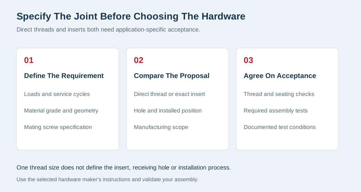
Your drawing should define the final joint and the geometry needed to manufacture it.
For direct threads, specify the thread system, size, pitch, usable depth and location. Distinguish usable threaded depth from total drilled depth.
For inserts, identify the manufacturer, series and part number where specified. Include installed position and any restrictions on substitution.
SPIROL warns that receiving-hole size affects performance and installation stress. It also identifies screw bottoming as a potential jack-out mechanism.
Use the selected insert’s current guidance for hole geometry. Confirm screw length and mating-part thickness across the complete tolerance stack.
Ask these questions during the drawing review:
- Is the hole blind or through?
- What usable thread engagement must the screw achieve?
- Can the proposed screw bottom out before the joint seats?
- Does the local geometry accommodate the selected insert?
- Which dimensions require inspection before and after installation?
These questions support a review; they do not replace a qualified joint design.
Which Failure Are You Actually Trying To Prevent?
Identify the failure mechanism before changing the thread or adding hardware.
A stripped female thread, a rotating insert and a cracked boss are different problems. Record what failed and when it happened.
| Observation | Review Before Changing The Design |
|---|---|
| Screw turns without holding in direct threads | Screw identity, engagement, thread damage and assembly history |
| Insert rotates during tightening | Receiving-hole conformity, installation records and local geometry |
| Insert lifts from its seat | Screw length, mating component, seating and axial loading |
| Plastic cracks around the hole | Hole condition, surrounding material and installation process |
| Joint loosens after use | Complete load path, servicing, environment and retained clamping requirement |
Treat these entries as investigation prompts, not diagnoses from a photograph. Preserve failed parts and compare them with accepted samples.
For each proposed correction, write down the expected improvement. Then define the measurement or test that would demonstrate it.
Avoid changing hole size, insert series and installation settings simultaneously without recording each change. Otherwise, the successful trial may be difficult to reproduce.
How Should You Validate The Finished Joint?
Validate the features and loading conditions that could cause failure in your assembly.
Start with thread conformity, position and usable depth. For installed hardware, check alignment, seating and visible damage.
Then define application tests, such as agreed assembly cycles or retention checks. State the sample quantity and acceptance criteria before testing.
Separate screw tightening torque from insert installation settings. Also distinguish application loading from destructive test results.
Record the material grade, screw specification and test conditions. Otherwise, different test reports may describe different assemblies.
Your quality and inspection plan should identify which checks are routine and which need separate agreement.
For broader drawing preparation, use our plastic machining tolerance checklist.
Separate Dimensional Checks From Performance Tests
Use separate acceptance records for geometry and application performance. They answer different questions and may need different samples.
A dimensional report can record thread position, installed depth and surrounding geometry. A performance report should describe the fixture and loading direction.
State whether each test is destructive. Do not return destructively tested samples to the production batch as ordinary accepted components.
For repeated assembly, define the screw, tightening procedure and number of cycles. Record the condition after testing, rather than only saying “passed.”
You may also need to evaluate the assembled cover or bracket. Testing an isolated insert may omit important mating-component effects.
Define The Complete Clamping Path
Check what carries the clamping force between the screw head and the threaded connection.
A threaded insert and a compression limiter serve different functions. An insert provides a female thread; a limiter can restrict compression in the plastic stack.
SPIROL’s compression-limiter guidance highlights alignment with the insert to avoid jack-out.
Do not assume that adding an insert solves every clamping problem. Ask whether the mating component requires a separate load-path review.
The appropriate solution depends on your assembly. Any limiter, washer or spacer should appear in the agreed bill of materials.
What Changes The Total Cost?
Compare the cost of an accepted assembly, including hardware and validation, rather than the price of machining one hole.
Ask each supplier to quote against the same drawing revision, grade, quantity and inspection requirements.
For inserts, clarify whether procurement and installation are included. Identify any supplied hardware and responsibility for its conformity.
For either option, review the consequence of a rejected joint. A small threaded feature can affect the usability of a larger component.
A trial batch can help resolve uncertain installation or inspection requirements before committing the full order. Define its purpose in advance.
Do not request extra operations without a clear requirement. Equally, do not remove necessary checks merely to reduce the initial quotation.
Keep Quotation Assumptions Visible
Ask the supplier to list exclusions and unresolved requirements. A quotation should distinguish the machined component from any optional assembly operation.
Confirm who approves hardware substitutions and revised receiving-hole dimensions. Record that approval against the drawing revision used for production.
If the trial changes the process, update the quotation and inspection plan together. Do not leave production relying on an email description.
For recurring orders, retain the approved hardware identity and relevant setup records. Changes in supplier or material grade should trigger an agreed review.
This documentation makes later price comparisons more meaningful. It also helps you distinguish an intentional design change from an unexplained production variation.
How Would You Compare Options For A Removable Cover?
Compare both proposals against the same servicing and acceptance requirements before choosing a thread solution.
Consider a hypothetical machined enclosure with a removable cover. This example illustrates a review process; it is not a TOPS customer case.
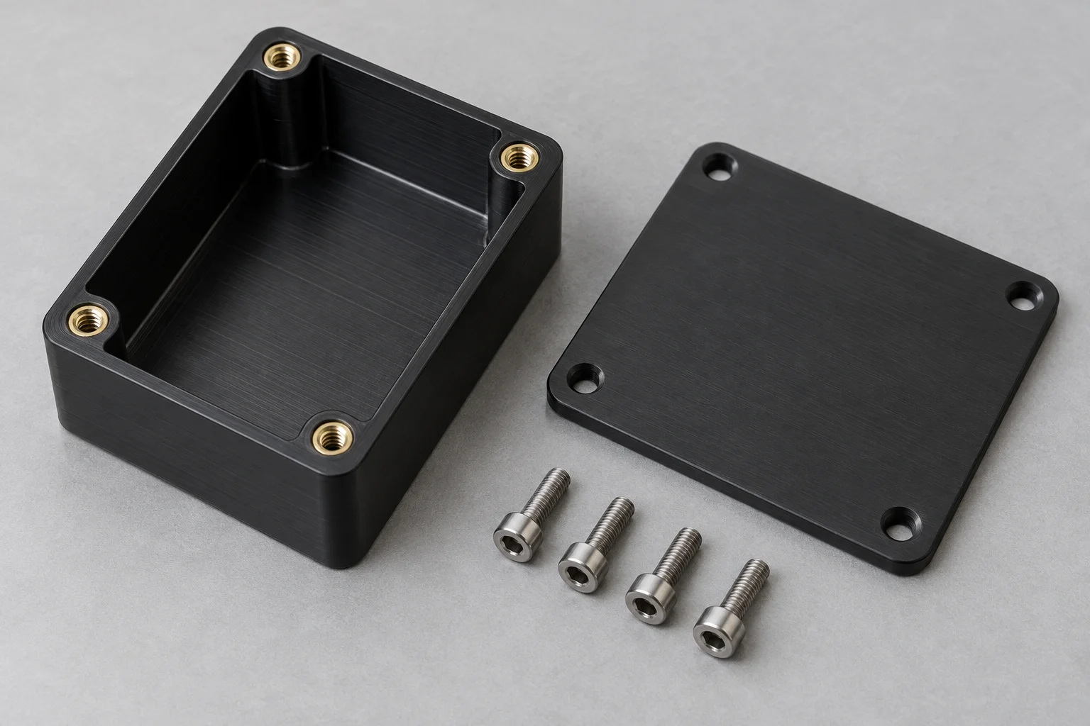
Your first question is how the cover will be used. A permanently closed assembly differs from one opened during routine maintenance.
Next, identify the enclosure grade, cover thickness and screw specification. Define the required installed condition and servicing procedure.
Ask for two proposals if both remain feasible: directly tapped holes and a specified insert arrangement. Keep the acceptance requirements identical.
For the insert proposal, confirm receiving geometry, hardware procurement and installation responsibility. For direct threads, confirm usable depth and inspection requirements.
Review how either proposal accommodates screw length across the assembly stack. A screw should not be selected from hole depth alone.
Finally, agree on a representative trial and its acceptance records. Approve the proposal that meets your requirements with a repeatable manufacturing scope.
If neither proposal succeeds, revisit the local geometry or assembly concept. Selecting a different insert is only one possible design change.
What Can TOPS Plastics Review With Your RFQ?
TOPS Plastics can review your drawing-based plastic machining requirements and confirm the proposed scope in a quotation.
For custom plastic CNC machining, send your drawing, CAD file, material grade, quantity and critical joint requirements.
Include the screw specification and expected servicing conditions. For inserts, provide the required hardware part number and installation requirements.
If you need installation, retention testing or special reports, request confirmation explicitly. Do not assume these operations are included automatically.
The quotation should resolve any remaining capability or acceptance questions before production approval.
Frequently Asked Questions
These answers clarify common thread-selection decisions without prescribing universal dimensions or load limits.
Do All Plastic Parts Need Metal Threaded Inserts?
No. Direct threads may meet the requirement. Evaluate the actual grade, geometry, loading and servicing conditions before adding hardware.
Are Threaded Inserts Always Stronger Than Direct Threads?
No universal comparison applies. The selected insert, surrounding plastic and installation quality determine the assembly’s performance.
Can I Specify An Insert Using Only Its Internal Thread Size?
That usually leaves important details unresolved. Specify the hardware design and receiving geometry, together with the required installed condition.
Can The Same Insert Hole Be Used For Every Plastic Grade?
Do not assume so. Ask the insert manufacturer to confirm the design for your exact grade, including any fillers.
Is Passing A Thread Gauge Enough To Approve The Joint?
Thread inspection alone does not establish application performance. Agree on any additional assembly or retention validation your design requires.
Choose The Joint Before Releasing The Drawing
Define loads, servicing and acceptance first. Then compare direct threads and the specific insert proposal. To discuss manufacture, contact us with your drawing, grade, quantity and joint requirements.