
Plastic wear pad design connects the sliding surface, supporting structure and maintenance plan. You need a documented material grade, realistic contact conditions and mounting that protects the running face. This guide explains how to specify custom machined pads without assuming a universal load rating or replacement interval.
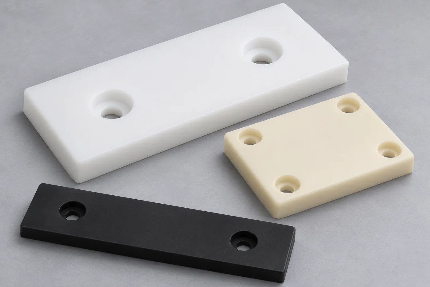
Define What Your Wear Pad Must Control
Your wear pad specification should identify the sliding interface, permitted movement and consequence of excessive wear.
Start with the machine function. A guide pad controls lateral movement, while a supporting slide plate carries a different loading arrangement. Identify which surfaces touch, where forces enter and how the assembly moves throughout its stroke.
Record normal load, occasional overload, sliding speed, dwell periods and reversals. Include startup after extended shutdown. A pad carrying a stationary load overnight presents different questions from a continuously moving conveyor guide.
Describe the environment around the actual interface. Dust, water, cleaning agents and nearby heat sources can change the operating conditions. State whether lubrication is prohibited, optional or required. Do not describe a contaminated installation simply as dry running.
Explain what failure means for your equipment. Your limit might involve excessive clearance, surface marking, unstable movement or potential contact with mounting hardware. Defining that limit helps you select meaningful dimensions, inspection methods and maintenance checks.
Compare Documented Grades Before Selecting A Polymer
You should screen exact stock-shape grades against the application rather than purchasing a wear pad by color or resin family.
UHMW-PE, nylon, PET and POM are possible candidates for different sliding applications. Modified grades may address specific friction or wear requirements. Your shortlist still needs relevant property data and evidence matching the intended operating conditions.
| Candidate | Reason To Include In Screening | Question To Resolve |
|---|---|---|
| UHMW-PE | General sliding guides and replaceable wear surfaces | Does deformation or temperature limit your geometry? |
| Nylon | Toughness and mechanically loaded sliding components | What moisture condition defines dimensions and clearance? |
| PET Or POM | Applications emphasizing dimensional control | Does the grade suit the counterface and exposure? |
| Modified Engineering Plastic | A documented requirement beyond the base grade | Are test conditions relevant to your installation? |
The Mitsubishi Chemical wear-strip overview identifies UHMW-PE, PET and nylon among common wear-strip materials. Use this as a screening reference. Its application examples do not establish a rating for your pad or demonstrate TOPS customer experience.
Ask for the grade designation, stock form and applicable documentation. A change from natural stock to a filled grade can affect more than appearance. Compare environmental compatibility, machining requirements and relevant sliding data before approving a substitution.
Avoid selecting the most expensive polymer as an automatic precaution. Higher temperature capability may not address poor support, abrasive contamination or an unsuitable counterface. Establish the limiting mechanism before paying for a material change.
Evaluate Contact Area And Long-Term Deformation
You need the actual supported contact area and loading arrangement before judging a wear pad's mechanical suitability.
A large outside footprint does not guarantee uniform contact. Misalignment, frame distortion or a proud fastener can concentrate load near an edge. Consider the assembled structure rather than dividing force by the entire rectangular outline without review.
Separate short-term compression from deformation during sustained loading. A pad may initially fit correctly while its supported clearance changes during service. Assess the exact grade at the relevant load duration and temperature. Do not treat a room-temperature strength value as a long-term allowable stress.
Check every operating position. A carriage might transfer load between pads as it extends, reverses or carries an offset payload. Your drawing package should identify those load cases and the supporting geometry associated with each case.
Where sliding pressure and speed influence your screen, use consistent definitions and units. Published limits reflect particular test arrangements. They cannot independently establish acceptable temperature, wear or service life for a rectangular pad assembly.
The plastic creep guide explains why loading time belongs in a polymer design review. Use that distinction when discussing allowable movement with your design owner.
Keep Mounting Hardware Below The Running Surface
Your retention design must secure the pad while preserving clearance between the moving component and mounting hardware throughout service.
Define the running face, backing face and mounting features on the drawing. Show counterbore dimensions and the actual fastener arrangement. Include the minimum acceptable remaining material above hardware as part of your replacement review.
Check this relationship using the assembled fastener, not just the nominal screw description. Head height, washers, recess depth and seating condition can change the available clearance. A loose screw or trapped debris can also defeat the intended arrangement.
The mounting illustration shows a conceptual pad supported on a backing plate, with hardware recessed below the running face. It is a review aid rather than an approved fastening arrangement or installation procedure.
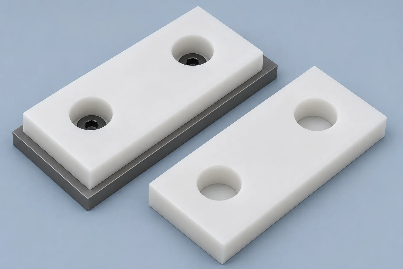
Avoid prescribing a universal tightening torque for plastic pads. Fastener size, support, grade, retention method and temperature affect the result. Have the responsible engineer define the arrangement and assembly procedure, including any required hardware or mechanical stops.
Plan maintenance access at the design stage. Confirm whether technicians can remove the pad without dismantling unrelated equipment. Accessible mounting and identifiable replacement parts can reduce service disruption without changing the sliding material.
Allow Movement Without Losing Location
Your mounting arrangement should accommodate expected dimensional changes while maintaining the pad's required position and support.
A long polymer strip and its metal support may change dimensions differently with temperature. Moisture can introduce another change for susceptible grades. Identify the operating range and assembly condition before deciding how holes, slots or retainers should locate the part.
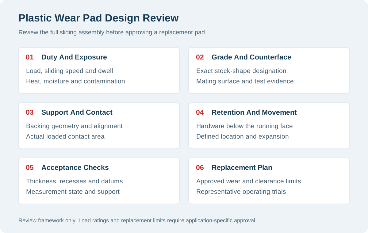
Use a defined locating strategy rather than adding elongated holes everywhere. Establish which feature controls position and where movement is allowed. Check that fasteners, shoulders or clamps do not unintentionally prevent the movement your design requires.
Review available clearance along the whole pad. End stops, adjoining segments and nearby guards may become interference points after installation. A nominal gap needs an associated temperature and material condition if different teams must verify it consistently.
Consult the plastic thermal expansion guide when documenting those states. Your assembly review should distinguish free movement from deformation caused by restraint.
Do not assume movement allowance can compensate for an inadequately supported backing face. Retention, location and support perform different functions. Review each function explicitly before approving a drawing revision.
Specify The Counterface And Contamination Conditions
Wear performance depends on the sliding pair and environment, so the polymer cannot be evaluated in isolation.
Identify the opposing material, coating and surface condition. Include joints, weld transitions, damaged areas and direction changes along the sliding path. A smooth test coupon does not represent a corroded rail or an uneven production assembly.
Ensinger's friction and wear guidance explains why published friction values depend on material pairing and test conditions. Treat those values as comparative evidence. They are not fixed constants for every installed pad.
Describe contamination realistically. Loose particles may enter from the product, surroundings or wear elsewhere in the machine. Your design review should address where particles collect and how inspection or cleaning removes them.
Evaluate grooves or relief features according to their purpose. A groove intended to manage debris also changes the contact surface and local geometry. Do not add features solely because a previous pad had them. Review their effect on support, cleaning and the mating component.
If lubrication is proposed, verify compatibility and maintenance requirements. A lubricant can affect both sliding behavior and the polymer itself. Record the exact product and application method instead of allowing uncontrolled workshop substitutes.
Agree On Machining And Inspection Requirements
Your drawing should distinguish functional dimensions, mounting features and cosmetic expectations before the supplier plans machining.
Prioritize thickness where it establishes installed clearance. Identify the relationship between running and backing faces. Specify holes relative to functional datums, including any locating features. Avoid applying the tightest tolerance to every dimension without a functional reason.
Use a manufacturing review sequence that connects material preparation with acceptance:
- Confirm the drawing revision, grade, quantity and documentation requirements.
- Review stock availability, blank dimensions and relevant material condition.
- Agree on machining access, support surfaces and practical feature geometry.
- Define edge treatment without changing required contact or locating features.
- Inspect functional dimensions using the agreed fixture and measurement condition.
- Protect finished faces and identify parts for receiving and maintenance.
A flexible pad can respond to the measuring fixture and contact force. State whether inspection occurs freely supported or under defined restraint. Where face geometry matters, use the plastic flatness guide to frame that discussion.
| Feature | Acceptance Question |
|---|---|
| Running Thickness | Will the installed pad establish the intended clearance? |
| Mounting Recess | Is the agreed hardware clearance preserved? |
| Backing Face | Does inspection represent the intended support arrangement? |
| Locating Features | Can you install the pad without unintended restraint? |
| Edges And Surfaces | Could damage affect travel, handling or the mating component? |
Validate Wear And Establish Replacement Criteria
You should define measurable replacement criteria before using operating trials to approve a pad design.
Choose observations that reflect your machine's failure limits. Record remaining thickness, guide clearance, movement quality and hardware condition as appropriate. Specify where measurements occur so different technicians can compare results.
A trial should reproduce the relevant counterface, loading, speed, environment and maintenance practice. Include representative reversals and stationary loading where applicable. Track changes over time rather than recording only whether the machine initially runs.
Fraunhofer IWM's polymer tribology research distinguishes material testing from component and system evaluation. This supports a staged validation approach. A laboratory ranking alone cannot settle every installation question.
Set stopping criteria before hardware becomes exposed or guidance becomes unacceptable. The appropriate remaining thickness depends on your pad, fasteners and machine risk assessment. This article does not prescribe a universal wear allowance or inspection interval.
If you change grade, backing geometry or lubrication after approval, review whether earlier trial results remain applicable. Keep approved samples and records linked to the relevant drawing revision. Otherwise, a replacement order can introduce an unreviewed design change.
Record A Baseline After Installation
Measure the approved assembly before routine operation begins. Record pad identification, installed clearance and the locations used for thickness checks. Include the measurement method and machine condition so future readings have a useful reference.
When wear appears uneven, inspect the opposing surface and supporting structure before ordering a harder grade. Localized damage may indicate misalignment, trapped particles or movement at the mounting interface. Preserve the removed pad for review instead of discarding evidence immediately.
Compare Quotes Against The Same Functional Scope
A useful wear pad quotation should cover the same grade, drawing, inspection evidence and delivery requirements across suppliers.
Stock size, material removal, mounting complexity and quantity affect the manufacturing scope. Inspection, documentation, identification and protective packaging add further requirements. Evaluate total replacement effort alongside part price, especially where access or downtime drives maintenance cost.
TOPS describes drawing-based machining of mounting holes, counterbores, grooves and wear allowances on its plastic wear pads page. Use that scope to begin a project review. Confirm grade availability and inspection requirements for your specific part.
Do not interpret a manufacturing quotation as approval of the machine design. Separate supplier responsibilities from the design owner's load assessment, mounting decisions and operating validation. Record any proposed deviations before purchase approval.
Consider another arrangement when your required movement, temperature or consequential failure risk cannot be supported by adequate evidence. A different material, rolling interface or redesigned support may deserve evaluation. A replaceable polymer pad is one design option, not a universal solution.
Plastic Wear Pad Design FAQ
These answers help you prepare a drawing package and ask focused questions before ordering machined wear pads.
Is UHMW Always The Best Wear Pad Material?
No. Evaluate the exact grade against deformation, temperature, contamination and dimensional requirements. Compare relevant evidence for your intended sliding pair.
Does A Low Friction Value Guarantee Low Wear?
No. Friction and wear describe different outcomes. Check the test conditions and validate the behavior relevant to your machine.
How Thick Should Your Wear Pad Be?
Thickness depends on support, clearance, mounting hardware and replacement requirements. Establish those relationships before specifying stock thickness.
Can You Use The Same Pad Without Lubrication?
Only when your grade and operating arrangement support that condition. Verify performance and compatibility before removing an existing lubrication requirement.
Should Every Mounting Hole Be A Slot?
No. Define location and movement deliberately. Uncontrolled slots may change position without solving the actual restraint problem.
Can You Copy A Worn Pad From A Sample?
A sample helps identify interfaces, but wear can hide original dimensions. Obtain approval for reconstructed thickness and mounting details.
When Should You Replace A Pad?
Use approved limits for remaining thickness, installed clearance and hardware protection. Establish inspection intervals from operating evidence and machine risk.
What Information Does A Supplier Need?
Provide drawings, exact grade, quantities, mating details and operating conditions. Include functional tolerances, inspection requirements and documentation expectations.
Request A Wear Pad Drawing Review
A useful plastic wear pad design defines the sliding pair, support, retention and replacement limits together. Send your drawing, grade, quantities and operating conditions. Contact us to confirm machining feasibility and quotation scope for your part.