
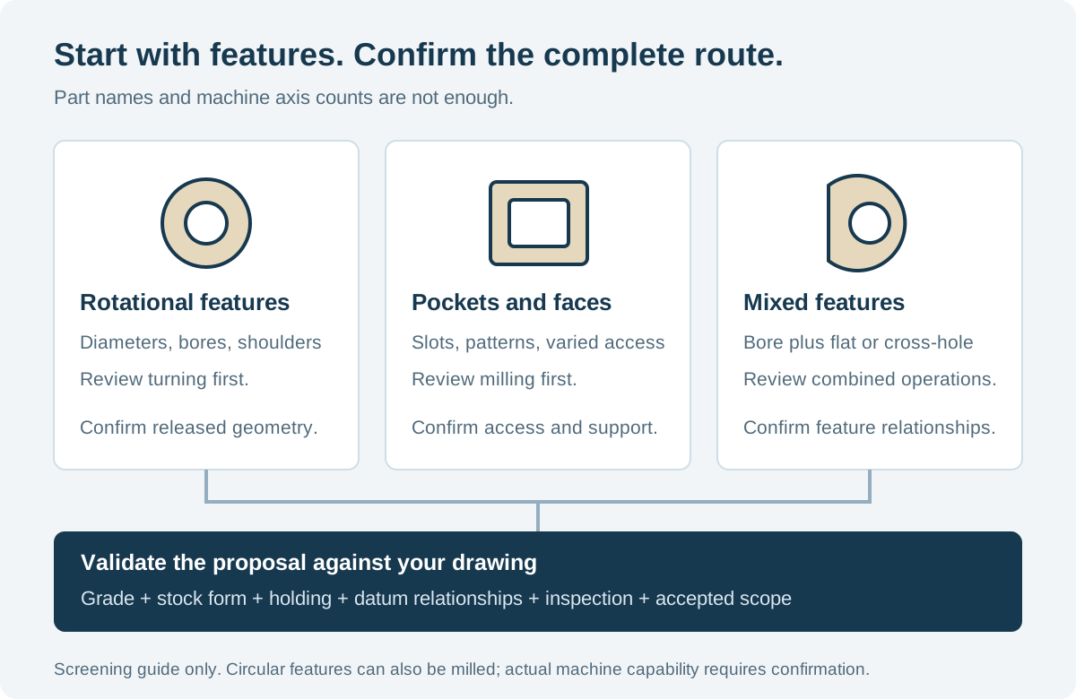
For CNC turning vs milling for plastic parts, start with the functional geometry. Turning suits features around a common axis. Milling suits pockets, flats and varied tool approaches. Some parts need both. Compare material behavior, holding and inspection before approving the route.
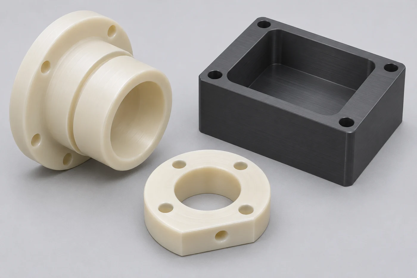
What Is The Difference Between CNC Turning And Milling?
Turning usually rotates the workpiece, while milling uses a rotating cutter to remove material from a supported component.
In turning, the cutting tool follows the rotating workpiece to create diameters, faces and profiles. In milling, the cutter and machine axes create features across selected surfaces. Machine configurations can combine these functions, so the distinction describes operations rather than every possible machine.
The Mitsubishi Chemical Group machinist’s toolkit explains plastic turning and milling alongside material-specific machining considerations. Use its process overview as technical background. Your supplier still needs the actual geometry and grade to propose a route.
For purchasing, ask which operation creates each critical feature. That question is more useful than requesting an impressive machine description. It connects the manufacturing proposal to the result your drawing requires.
When Does Plastic Turning Make Sense?
Turning is a strong starting point when functional diameters, bores and shoulders share a common axis.
Bushings, sleeves, rings, rollers and spacers often fit this pattern. Turning can address outside profiles and internal features where access permits. The full drawing determines whether additional operations are necessary.
Your bore-to-outside relationship may matter more than either diameter alone. Identify that relationship using the appropriate drawing controls. Avoid relying on an informal request for concentricity without clarifying the actual functional requirement.
A long sleeve also needs sufficient support during machining and inspection. A thin ring may change shape under gripping pressure. These risks remain even when the component looks like a straightforward turning job.
When Does Plastic Milling Make Sense?
Milling suits pockets, slots, planar faces, hole patterns and other features that do not follow one rotational profile.
Housings, fixture plates, manifolds and brackets commonly contain these features. Cutter access and remaining material affect the proposed sequence. A part may need several setups or a suitable multi-axis approach.
Your drawing should identify which faces locate the component in service. It should also show which hole patterns or pockets relate to those faces. Without that information, the supplier cannot fully connect the machining route to acceptance.
Milling can also create circular features. A round shape does not automatically require a lathe. Compare tool access, functional relationships, stock use and support before deciding which operation should create the feature.
Can One Plastic Component Need Both Processes?
A component needs a combined route when rotational and nonrotational features must coexist with controlled relationships.
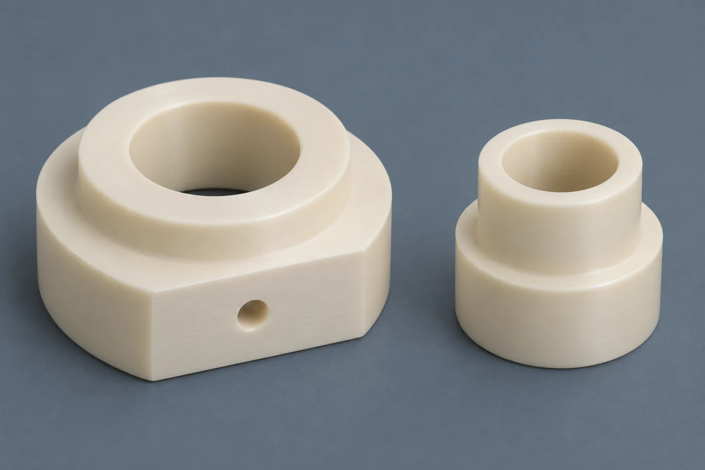
A sleeve with a mounting flat is one example. Its main bore and outside diameter may favor turning. Its flat or cross-hole may need another operation.
The secondary-feature illustration shows this geometry concept. It does not prescribe a machine, fixture or operation sequence. Your supplier should explain how the proposed route preserves the important feature relationships.
Some lathes provide driven tooling for operations beyond conventional turning. The Haas lathe operator manual describes live tooling for milling, drilling and slotting. This is a machine-function reference, not evidence that TOPS owns a particular machine or option.
Compare a combined machine route with separate turning and milling operations where relevant. Neither is automatically superior. Access, holding, setup effort and inspection can change the preferred choice.
Which Route Fits Your Part Features?
Use your functional features to shortlist routes before comparing detailed quotations.
The table provides review directions, not approved manufacturing recipes. Material examples are candidates for discussion. Their suitability depends on the actual grade, application and required evidence.
| Feature Or Component | Route To Review | Example Material Candidates | Main Question |
|---|---|---|---|
| Stepped sleeve with an axial bore | Turning and boring | POM, PEEK or PTFE | Can the required diameter relationships survive gripping and release? |
| Housing with open pockets | Milling and drilling | POM, PEI or PEEK | Can tools reach features while the remaining walls stay supported? |
| Flanged part with mounting flats | Turning plus milling, or suitable combined operations | POM or PEEK | How are the flat and hole related to the primary axis? |
| Ported fluid block | Milling, drilling and boring | PVDF or a qualified alternative | Are passage intersections, ports and sealing features accessible? |
| Plate with a hole pattern | Milling and drilling | PET, POM or another approved stock | Which faces and datums define the hole relationship? |
Do not choose material from this table alone. Start with your operating requirements and grade approval. Then confirm what stock and process route can produce the defined component.
Why Do Datums And Setup Transfers Matter?
Datums and setup transfers matter because individually acceptable features can still have an unacceptable relationship to each other.
When a part moves between setups, the supplier must re-establish its location and orientation. The chosen locating features influence subsequent work. Identify which relationships matter before asking the supplier to reduce the number of setups.
A bore and mounting flat may each meet their size requirements. Their relative location can still affect assembly. Your drawing needs the controls that express the intended relationship.
Ask how the route will create and inspect those relationships. A single setup may help certain features, but it is not an automatic quality guarantee. Poor access or distorted holding can undermine an apparently simple route.
For repeat orders, keep the approved datum strategy and acceptance method visible. Review proposed process changes when they affect the requirement. Do not demand identical machinery when a different validated route can satisfy the same drawing.
How Does Workholding Affect The Process Choice?
Workholding affects route selection because plastic components can deform under cutting or holding forces.
A lathe needs an appropriate gripping and supporting arrangement. A milling setup also needs support without unintentionally bending the part. The best arrangement depends on geometry, material and the features being machined.
Ensinger’s plastic machining FAQ emphasizes suitable sharp tooling and heat management for engineering-plastic stock. These considerations apply alongside workholding. They do not provide a universal setup or cutting parameter for your component.
Ask which surfaces may carry holding contact and whether temporary manufacturing allowances are needed. Approve any change that affects the delivered design. Do not let an unrecorded grip modification become an unintended product feature.
The thin-wall machining guide covers related support questions. Use it when comparing delicate turned and milled geometries. Both routes need inspection of the required released or otherwise specified condition.
Does Material Grade Change The Preferred Route?
Material grade can change the practical tooling, support and inspection strategy within either turning or milling.
An unfilled polymer and a reinforced formulation should not be treated as identical machining materials. Softer stock can present different holding risks from stiffer stock. Application-specific compounds may also need additional documentation or contamination controls.
Specify the exact grade before requesting a final production quotation. Identify whether rod, plate or tubular stock is acceptable. Stock form can affect material usage and what geometry is practical to obtain.
For filled grades, review the reinforced plastics machining guide. Your supplier should evaluate the actual formulation. A process selected for one grade should not silently authorize a substitute.
What Design Details Help Both Processes?
Useful design details give the supplier clear tool access, functional priorities and measurable acceptance requirements.
Review these points before freezing the drawing:
- Provide accessible internal radii where the function permits them.
- Identify deep bores and pockets requiring special reach.
- Define threads, engagement and related sealing requirements.
- Separate cosmetic surfaces from mating and locating surfaces.
- Show relevant cross-holes and internal intersections completely.
- Mark critical released dimensions and approved inspection conditions.
For pockets, use the plastic pocket design guide to structure the access discussion. For sleeves, review bore depth, wall thickness and gripping space. Do not force the same geometric rules onto every component.
Avoid prescribing a cutter or operation sequence without a functional reason. Give the supplier room to propose a feasible route. Keep design changes subject to your responsible engineer’s approval.
How Should You Specify Surface And Edge Requirements?
Specify surface and edge requirements by function, rather than assuming one process automatically produces the desired finish.
A turned surface and a milled surface can show different tool patterns. Their acceptability depends on the mating or appearance requirement. Define the actual characteristic that matters instead of requesting an undefined perfect finish.
Internal intersections and exits deserve particular attention where edges affect flow, assembly or handling. Review the plastic deburring guide for practical acceptance questions. Identify inaccessible features before the route is accepted.
Secondary finishing can change dimensions or surface condition. Agree its scope and subsequent inspection. Keep the final accepted state consistent with the delivered component.
What Should The Inspection Plan Compare?
Your inspection plan should evaluate the features and relationships that justified the selected route.
For turned parts, identify critical diameters, bores, lengths and axis-related requirements. For milled parts, identify functional faces, pockets and feature locations. Combined parts need both sets of questions.
State the relevant support, temperature and measurement conditions. A part held during manufacture may differ after release. Do not compare supplier and receiving results without checking that both describe the same condition.
Use the first-article inspection guide to connect material identity, drawing revision and measured evidence. Confirm any separate assembly tests. A machining inspection report does not automatically qualify the entire application.
Which Route Costs Less?
The lower-cost route is the one that meets your complete acceptance scope with practical stock use and process effort.
Turning can be efficient for suitable rotational geometry. Milling can be efficient for accessible prismatic features. Neither statement establishes a universal price advantage for every part.
Compare blank size, material removed, setups, special holding and inspection work. Add secondary operations, finishing, records and packaging. A quote that excludes difficult features is not directly comparable with a complete offer.
Provide initial quantities and expected repeat demand. Setup work may be shared differently across production volumes. Do not assume that a prototype price scales linearly into a larger order.
Ask suppliers to identify scope differences clearly. Compare the accepted component, rather than the hourly machine rate alone. Request a drawing-based quotation instead of relying on generic per-part prices.
When Should You Reconsider The Proposed Route?
Reconsider the route when tool access, support or measurement limitations prevent a justified path to your drawing requirements.
Your design may need another stock form or a modified feature. A combined route may be more practical than insisting on one process. An added axis may improve access without resolving a material or holding problem.
Before approving changes, identify why the original proposal falls short. Review the drawing and functional need with your engineer. Keep any accepted modification in the controlled records.
What Can You Review With TOPS Plastics?
You can discuss both routes through TOPS Plastics’ existing CNC plastic turning and milling services.
The plastic turning service page describes cylindrical and rotational component review. The plastic milling service page covers pockets, faces and related features. Use them to prepare a complete project enquiry.
Confirm actual material availability, component feasibility and inspection deliverables before ordering. Ask about any required equipment or special testing individually. This article does not establish a machine inventory, certification or numerical tolerance guarantee.
Frequently Asked Questions
Your turning-versus-milling decision should follow the complete drawing; these answers address common selection shortcuts.
Does Every Round Plastic Part Need Turning?
No. Milling can create circular features too. Compare functional relationships, access, stock and support. Turning is a useful starting point when the main geometry follows a common axis.
Can A Turned Part Have A Flat Or Cross-Hole?
Yes, if an appropriate additional operation is feasible. Review separate milling or suitable combined equipment. Define how those features relate to the turned geometry.
Do More Machine Axes Mean Better Plastic Parts?
No automatic improvement follows from the axis count. Extra axes can help access or setup planning. Material behavior, holding and inspection still require control.
Which Process Holds Tighter Tolerances?
Your attainable result depends on geometry, material, process and measurement method. Discuss the critical features on your drawing. Avoid assuming a universal tolerance advantage for either process.
Can You Use The Same Program After Changing Plastic Grade?
Do not assume an unchanged process remains suitable. The supplier should review the new grade and application requirements. Approve material substitutions and relevant process changes explicitly.
Should You Specify A Single Setup?
Specify the functional requirement first. A single setup may benefit some relationships but limit access to others. Ask the supplier to justify the proposed route.
Is A Smooth Surface Enough For Acceptance?
No. A smooth appearance does not prove dimensions, geometry or material identity. Agree the required inspections. Keep appearance criteria separate from functional measurements.
What Information Helps You Obtain A Useful Quote?
Send drawings, the exact grade, quantities and critical feature requirements. Include assembly relationships and inspection needs. Explain any unresolved route or design questions before production pricing.
Request A Process Review
For CNC turning vs milling for plastic parts, send your drawing, grade, quantities and critical acceptance requirements. Contact TOPS Plastics for a route review. Agree confidential-file handling before sharing sensitive drawings, and confirm the complete machining and inspection scope.