
Plastic thermal expansion can change clearances, mounting positions and inspection results as temperature changes. Design around the exact grade, relevant temperatures and assembly constraints. Calculate free expansion only as an initial estimate, then review the complete tolerance stack and validate critical installed conditions.
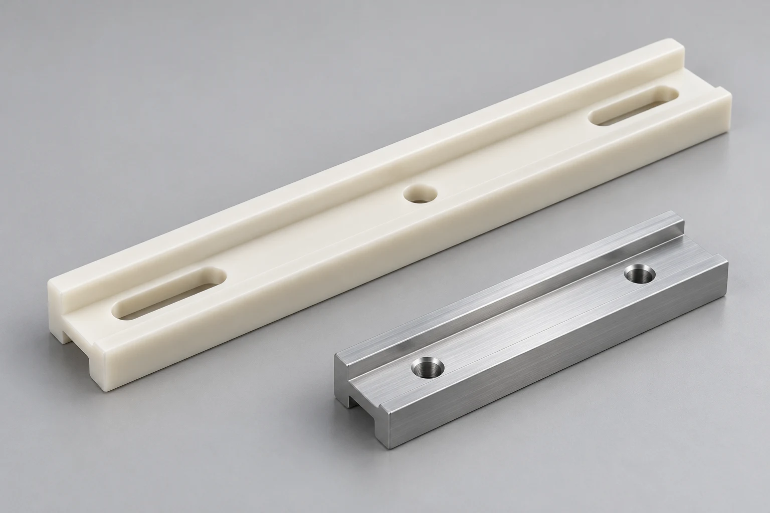
Why Can A Part Pass Inspection But Bind In Service?
A dimension accepted at inspection describes one defined condition. It does not automatically describe the same component inside warm equipment.
Consider the whole interface: plastic part, metal support, fasteners and available movement. Different components may experience different temperatures during operation.
A guide rail might fit during assembly yet contact a stop after heating. A cover might bow when its mounting prevents movement.
These are design questions alongside machining accuracy. Tightening the original dimensional tolerance does not automatically create adequate operating clearance.
Ensinger’s mechanical-engineering guidance identifies thermal expansion as a consideration when changing from metal to plastic.
For procurement, ask which temperature the drawing dimensions represent. Then identify the functional limits that must remain satisfied during service.
What Does The Thermal Expansion Coefficient Describe?
The coefficient of linear thermal expansion, often called CLTE, relates a length change to original length and temperature change.
Mitsubishi Chemical Group’s engineering design guide explains this property within its material-selection and design information.
A coefficient is useful only with its conditions. Identify the grade, temperature interval, direction and test basis before entering a value.
Do not copy one number from a generic polymer chart into every calculation. Ask whether it represents your material and temperature range.
Filled materials can require direction-specific information. Check whether the supplied data and stock orientation support the dimensions being assessed.
The coefficient also does not replace stiffness, creep or chemical-compatibility information. Those properties answer different questions about the operating assembly.
How Do You Estimate Free Length Change?
For a uniform temperature change, a constant-coefficient approximation is: ΔL = α × L₀ × ΔT.
Here, ΔL is length change, α is the expansion coefficient, L₀ is starting length and ΔT is temperature change.
Use compatible units throughout. A coefficient expressed per kelvin can use a Celsius temperature difference because their interval sizes match.
This simple model assumes uniform temperature, unconstrained expansion and a coefficient appropriate across the interval. State those assumptions beside the result.
It does not predict bending from a temperature gradient or stress caused by restraint. Those situations need a suitable assembly analysis.
For wider temperature ranges, ask the responsible analyst whether a constant coefficient remains acceptable. Use more appropriate property data when necessary.
Worked Example: Compare A Plastic Rail And Metal Support
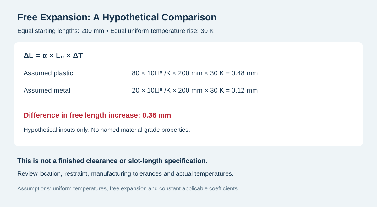
Consider two hypothetical freely expanding parts with the same starting length. The numbers below are arithmetic inputs, not properties of named grades.
| Input Or Result | Hypothetical Plastic | Hypothetical Metal |
|---|---|---|
| Starting length | 200 mm | 200 mm |
| Assumed coefficient | 80 × 10⁻⁶ /K | 20 × 10⁻⁶ /K |
| Uniform temperature increase | 30 K | 30 K |
| Estimated free length increase | 0.48 mm | 0.12 mm |
The estimated difference in free length increase is 0.36 mm. This comparison assumes both parts experience the same uniform temperature rise.
That difference is not automatically a required slot length, running clearance or drawing tolerance. The mounting reference determines where movement occurs.
If one end locates both parts, the relative movement accumulates toward the other end. A central locator changes the distribution.
Add fastener clearances, positioning tolerances and other relevant allowances separately. Avoid calling the free-expansion difference a finished design without those checks.
For CNC plastic machining, provide the released dimensions and explain which interfaces require a thermal review.
Which Calculation Inputs Deserve A Second Check?
Check the length between the features that actually constrain movement. Overall part length may differ from the relevant mounting span.
Confirm the starting temperature associated with that length. Mixing an inspection dimension with an installation temperature creates an inconsistent starting point.
Review coefficient units carefully. Values reported in micrometers per meter per kelvin require the corresponding conversion in the calculation.
Keep signs consistent when evaluating cooling. A negative temperature change represents contraction within the approximation, rather than a negative clearance requirement.
Use enough precision to avoid rounding away a meaningful difference. Report only the accuracy justified by the underlying data and assumptions.
Ask a second reviewer to reproduce critical arithmetic independently. Record the input revision so later material or temperature changes remain traceable.
Why Must You Compare Both Mating Components?
A fit depends on relative dimensions, so examine both sides of the interface. Include the shaft, housing or frame where applicable.
Do not assume every component follows ambient air temperature. Motors, process fluids, friction and cleaning can create different local temperature histories.
Document the temperatures used for each part in the calculation. Identify whether they are measured, specified or provisional estimates.
Cooling can be just as important as heating. Evaluate the relevant temperature extremes and intermediate conditions rather than checking only the hottest case.
A free ring and a restrained bushing do not share identical boundary conditions. Avoid applying unconstrained diameter changes directly to installed clearance.
Our plastic bushing clearance guide provides a framework for the related shaft, housing and installation questions.
How Should Mounting Features Accommodate Movement?
Begin by deciding which feature establishes position. Then identify the directions where the component needs freedom to move.
A slot may permit movement along one direction while another feature locates the part. Its orientation must match the intended movement.
Review washer contact and fastening conditions too. A correctly oriented slot cannot permit sliding if the joint clamps the component rigidly.
Loose hardware is not a universal solution. Retention, vibration, sealing and equipment requirements still apply to the mounting design.
Consider edge distance, remaining wall thickness and access when modifying holes. The supplier needs a complete feature definition to quote and machine it.
For plastic milling, mark slot geometry, datums and relevant contact faces separately on the drawing.
Ask the responsible designer to approve the movement strategy. A machine shop should not infer a critical mounting arrangement from an unfinished sketch.
Example: A Clear Panel Mounted To A Metal Frame
Consider a hypothetical clear panel attached to a rectangular metal frame. This is an illustrative review, not a tested customer installation.
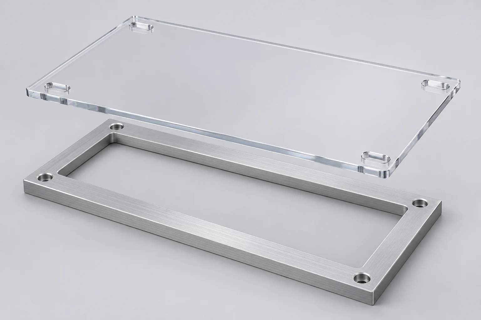
First, distinguish positioning from retention. Identify which features establish the panel location and which retain it during use.
Next, define the panel and frame temperatures. Include cleaning or shutdown conditions if they create a meaningful difference from normal operation.
Review the expansion directions and available movement around the perimeter. Check contact with adjacent panels, handles, seals and frame edges.
Compare the proposed slots with the hardware and clamping method. Confirm that the intended movement remains possible after assembly.
If the panel performs a protective function, thermal allowance is only one requirement. The responsible equipment designer must also assess protection and retention.
For polycarbonate components, specify the grade and required performance rather than relying on transparency alone.
Record the approved assembly details alongside the drawing. Replacing a washer or changing tightening practice can alter the intended behavior.
How Does Temperature Affect Dimensional Inspection?
Inspection should describe a reproducible condition. Agree on the part condition, measurement environment and method before comparing close results.
A part arriving from a different environment may not immediately match the measurement-room temperature. Its interior may also differ from its surface.
Do not prescribe one universal stabilization time for every material and geometry. Confirm a practical procedure for the particular component and measurement requirement.
Avoid measuring immediately after heat-generating processing when the acceptance plan requires a stabilized part. Record any agreed exceptions explicitly.
Ensinger’s machining FAQ discusses machining heat and the need to consider thermal expansion during processing.
Check how the measuring equipment and fixtures contact the part. Support, contact force and restraint can affect the interpretation of a dimensional result.
Our quality and inspection page helps organize project-specific inspection questions. Confirm special environmental or installed-condition checks separately.
What Belongs In A Practical Tolerance Stack?
Separate manufacturing variation from predictable temperature-related movement. Then combine the relevant terms using an agreed engineering method.
| Contribution | Information To Establish |
|---|---|
| Initial part size | Nominal dimensions, limits and reference condition |
| Mating hardware | Relevant dimensions and their permitted variation |
| Thermal change | Grade-specific data and component temperature cases |
| Location | Datum scheme and distribution of relative movement |
| Assembly | Fastener position, restraint, installation and contact |
| Other effects | Moisture, wear or long-term loading where relevant |
| Functional acceptance | Minimum clearance, maximum movement or retained engagement |
Do not subtract a thermal allowance twice because it appears in two documents. Identify where each contribution enters the calculation.
State whether the assessment uses worst-case limits, a statistical approach or another method. The choice needs an appropriate justification.
Our machining tolerance checklist can help structure the dimensional requirements before quotation.
How Should You Compare Candidate Materials?
Compare exact grades over the same temperature cases. An attractive room-temperature datasheet does not establish the complete operating fit.
Request the coefficient interval and direction along with its value. Also check whether the material evidence applies to the specified stock form.
For PEEK machining, identify the particular grade before assessing the proposed interface and service conditions.
For Delrin / POM machining, specify the required material designation instead of approving an unrestricted acetal substitution.
A lower coefficient may simplify one interface while another property limits suitability. Review chemicals, stiffness, wear, impact and electrical requirements together.
Do not choose a filled material solely to reduce expansion. Review its directional behavior, mating surfaces and manufacturing requirements with the responsible engineer.
Use our engineering-plastic selection guide to keep the wider application requirements visible during comparison.
What Should A Thermal Validation Plan Demonstrate?
Test the functional requirement, not just whether the part survives heating. Define what must remain free, aligned, retained or sealed.
Record the grade, drawing revision, hardware and assembly method. A result without those details can be difficult to apply to repeat orders.
Define temperature points, ramping conditions and dwell criteria appropriate to the application. Explain how component temperatures will be assessed.
Check relevant operating conditions at temperature where practical. A measurement taken after cooling may miss a temporary interference or movement problem.
Also examine the returned condition after the cycle when required. Identify whether any remaining change needs separate investigation.
Do not label a short trial a lifetime qualification without evidence. State the purpose, limitations and acceptance criteria of the test.
What Should You Include In The RFQ?
Provide enough context to separate a manufacturing request from an unresolved design decision. Keep provisional assumptions visible until they are approved.
| RFQ Item | Required Detail |
|---|---|
| Part definition | Drawing revision, CAD file, critical interfaces and quantity |
| Material | Exact grade, stock specification and substitution restrictions |
| Temperatures | Inspection, installation, operation and exceptional conditions |
| Mating parts | Relevant geometry, materials and temperature assumptions |
| Mounting | Datums, movement directions, fasteners and clamping arrangement |
| Acceptance | Required clearances, dimensional limits and verification method |
| Documentation | Inspection records, validation ownership and change control |
Ask the quotation to identify exclusions and open engineering questions. Resolve them before comparing offers solely on machining price.
Order evaluation quantities separately when the design still needs validation. Define which results are required before a repeat production release.
Which Changes Should Trigger Another Review?
Revisit the assessment when the grade, stock direction, temperature range or locating scheme changes. Identify these triggers in the approval record.
A replacement frame material can change relative movement even when the plastic drawing stays identical. Include mating-component changes in the review process.
Keep revised calculations connected to the released drawing and assembly instructions. A corrected spreadsheet alone does not update the shop-floor requirement.
How Can You Investigate A Temperature-Related Fit Complaint?
Record the condition where the problem occurs before changing the drawing. Note temperature, operating state, assembly history and affected interface.
Compare the free-state dimensions with the installed behavior. Avoid assuming that an acceptable loose part proves the assembly has adequate movement.
Check material identity and hardware changes. A substitute grade or revised washer can invalidate assumptions used in the original review.
Distinguish reversible thermal movement from wear, moisture effects and permanent distortion. More than one mechanism can contribute to the same symptom.
For sustained loading questions, consult our plastic creep guide rather than treating every dimensional change as thermal expansion.
Agree on a controlled comparison before assigning responsibility. Use the findings to revise the relevant requirement, inspection condition or mounting detail.
Frequently Asked Questions
Does A High Service Temperature Mean Low Thermal Expansion?
No. Service-temperature information and expansion coefficients describe different aspects of material behavior. Review both for the exact grade and application.
Is A Slot Always Necessary In A Plastic Mounting?
No. The design depends on part size, relative movement, restraint and functional requirements. Select and validate the appropriate mounting arrangement.
Can I Use One Coefficient For All Directions?
Only when the evidence supports that assumption. Check directional data, particularly for reinforced materials, before calculating critical dimensional changes.
Will A Tighter Machining Tolerance Prevent Thermal Binding?
Not automatically. Review the full operating clearance and tolerance stack. Tight manufacturing limits do not remove temperature-related movement.
Does Free Expansion Predict An Installed Bushing Bore?
Not by itself. Housing restraint, wall geometry, assembly and temperatures influence the installed interface. Use a suitable bearing-design assessment.
What Information Helps A Supplier Review My Drawing?
Send the exact grade, drawing, quantity and mating-interface details. Explain relevant temperatures and identify the dimensions or movement limits that matter.
Define Temperature Conditions Before Approving The Fit
Connect drawing dimensions to inspection conditions, operating temperatures and assembly constraints. Use grade-specific evidence, document assumptions and validate critical interfaces. Contact TOPS Plastics with your drawing and application details to discuss the machining requirements.