
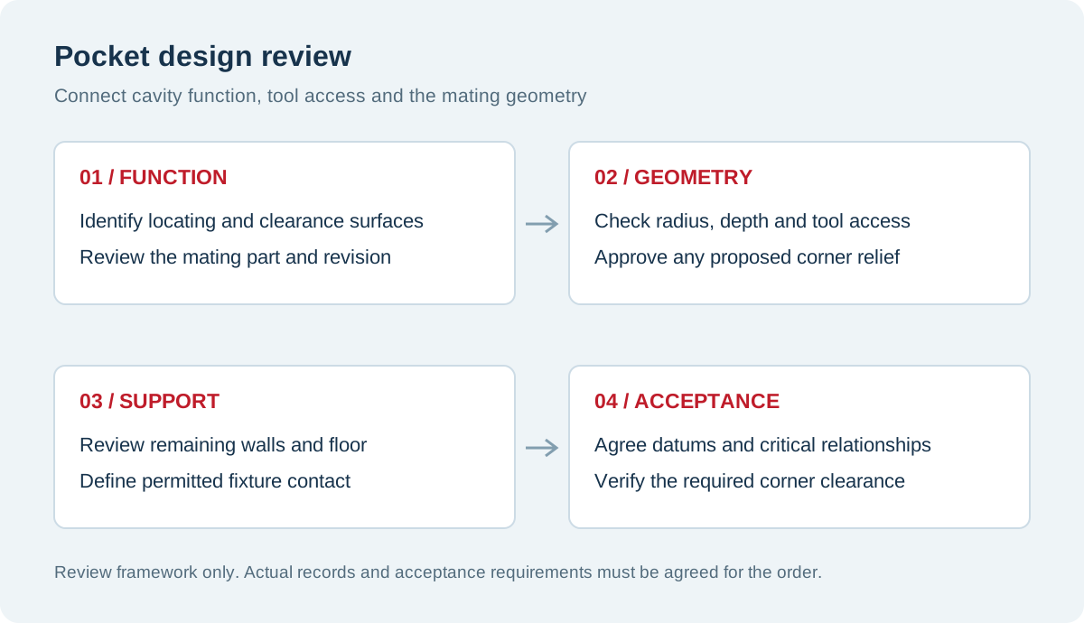
Design a machined plastic pocket around its function, the access needed to cut it and the way it will be inspected. A smaller internal radius is not automatically a better feature. When a corner has no functional reason to be tight, specifying it unnecessarily can constrain tool selection and complicate a deep-pocket operation.
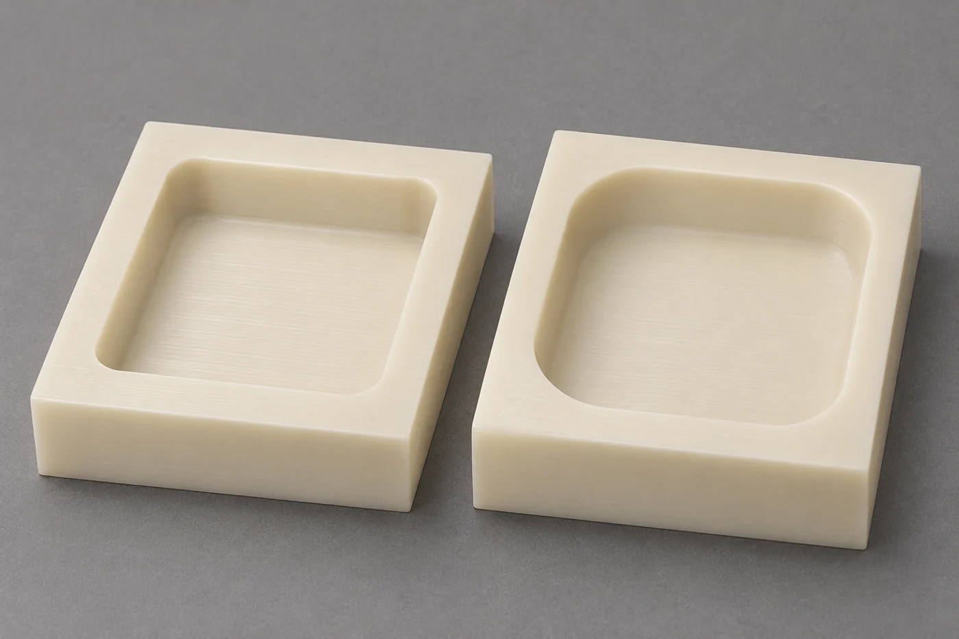
The useful purchasing discussion connects the pocket to its mating part, wall support, material grade and acceptance requirements. There is no universal depth-to-width limit or minimum radius suitable for every plastic component. This guide explains what to review before ordering a housing, fixture, insulator or other milled part with internal cavities.
Identify What The Pocket Actually Does
Begin with the reason material is being removed. A pocket may locate another component, provide clearance, reduce weight or create a working cavity. These functions lead to different controls. Identify which walls and floor regions are functional before assigning the same tight requirement to the whole feature.
A cavity used only for clearance may allow a larger corner radius or a different floor profile. A locating pocket may instead need a defined relationship to mounting datums. A fluid-related feature can introduce additional cleaning or sealing considerations. Describe those needs explicitly rather than asking the machinist to infer them from shape alone.
Review the surrounding assembly as well as the individual model. A design that looks clear in isolation may create an interference at an insert corner or leave no useful inspection access after assembly. Compare the relevant component revisions before approving the pocket geometry.
For broader manufacturing discussions, use the CNC plastic milling page. A drawing-based review is most useful when the intended function and permitted changes are provided with the model.
Understand Why Milled Internal Corners Have A Radius
A rotating end mill has a circular cutting envelope. In ordinary end milling, that geometry leaves a radius where vertical pocket walls meet. A sharp internal vertical corner therefore needs a separate manufacturing discussion rather than being treated as an ordinary result from a round cutter.
Quickparts’ CNC design guidance explains the connection between round tools and internal corner radii. The relevant design implication is to specify a corner that serves the component and can be reached by an appropriate tool. It does not establish one radius that suits every plastic, depth or machining setup.
Distinguish the vertical corner radius from the transition between the pocket wall and floor. They are different geometric features and can involve different tool shapes. If the drawing uses a general radius note, confirm which edges it governs so the supplier does not have to guess the intended detail.
The model and drawing should agree. An unspecified sharp-looking model corner with a different drawing note can create quoting assumptions that later become acceptance disputes. Resolve those conflicts before programming or material purchase.
Review Radius Together With Pocket Depth
A small corner radius can require a smaller tool to reach the final geometry. A deep pocket may also require additional reach. Consider these requirements together, because a tool arrangement that works near the top surface may become less practical when the same corner continues far below it.
Tool access includes more than the cutting diameter. The tool holder and noncutting portions also need clearance. Nearby walls, bosses or raised features can restrict the approach. Ask the supplier to review the complete cavity and surrounding geometry rather than approving a radius from a top-view sketch alone.
Avoid treating a published rule of thumb as a production guarantee. The identified material, tool, support and surface requirements influence what is feasible. A supplier review should establish the proposed approach and any exceptions for the actual drawing.
Where function permits, a larger corner radius or shallower cavity may simplify the route. That change must be approved by the design authority. The supplier should not silently alter a locating feature merely because a different corner would be easier to machine.
Check The Mating Part At Its Corners
A square external corner on an insert can interfere with the rounded internal corner of a pocket. Check the complete mating geometry rather than comparing only the nominal pocket length and width. A fit that appears correct on straight faces can still fail at the corners.
Possible design discussions include rounding the insert, enlarging the pocket radius where clearance allows or adding a localized corner relief. Each option changes geometry and may affect function. Evaluate sealing, strength, cleanliness and appearance before selecting a relief solely for manufacturing convenience.
The fit illustration shows an open polymer pocket beside a separate insert with rounded external corners. It illustrates a corner-clearance discussion. It does not define a tolerance, demonstrate an approved assembly or establish which material belongs in a real application.
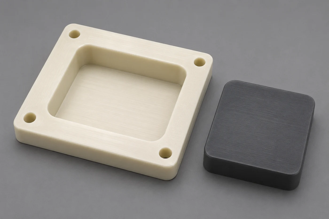
Record the approved relationship on the drawing. If clearance is functional, identify the relevant conditions and mating revision. The thermal expansion guide explains why a fit may also need review across operating temperatures rather than only at inspection.
Preserve Enough Material For Support
Pocket walls and floors must survive machining, handling and service. Removing material can leave a section that responds to cutting or clamping forces. Consider the remaining geometry, including local thin areas around mounting holes and transitions near an external edge.
A broad thin floor can be difficult to evaluate without a defined support condition. A tall open wall can move when restraint is released. The thin-wall plastic machining guide discusses how those features affect workholding and inspection.
Do not assume that increasing clamp force will solve a flexible-feature problem. The fixture needs to resist machining loads without imposing unacceptable distortion. Ask where the part can be supported and which surfaces must remain free from clamp marks.
Design changes such as a thicker local section or a permitted support tab may deserve review. Their usefulness depends on the actual function and assembly space. Approve changes through a controlled revision rather than leaving them as informal shop instructions.
| Feature to review | Question for the design team | Information for the supplier |
|---|---|---|
| Internal vertical corner | What radius or clearance is functional? | Approved radius and any permitted relief |
| Pocket depth | Does every region need the full depth? | Floor requirements and access constraints |
| Mating insert | Can its external corners clear the pocket? | Mating geometry, revision and fit condition |
| Remaining wall or floor | How is it supported during use and inspection? | Critical faces and allowed restraint |
| Mounting features | Do they preserve enough local material? | Datum scheme and assembly requirements |
Plan Chip Removal And Heat Control
A deep cavity can restrict the path for chips leaving the cutting zone. Review access for evacuation as well as access for the tool. Recutting trapped material or allowing it to accumulate can complicate finish and process control.
Mitsubishi Chemical Group’s machining toolkit emphasizes clearance and swarf removal in plastic machining. Use that guidance to organize a process review of the identified stock and operation. It does not replace a component-specific cutting strategy.
Tool condition and geometry deserve attention alongside the cooling method. Ensinger’s machining FAQ discusses sharp tooling and material-specific machining considerations. A pocket design review should allow the supplier to explain whether the proposed geometry constrains an otherwise suitable process.
If process fluids are proposed, review compatibility and cleaning needs. The plastic machining coolant guide addresses those questions. A deep feature may also need a clear handling sequence so retained fluid or debris does not remain an unexplained acceptance issue.
Consider Stock Removal And Released Shape
A large cavity can remove a substantial portion of the starting stock. The resulting component may respond differently from the original blank. Discuss the material condition and removal sequence, especially when the pocket is concentrated on one side of a broad plate.
The plastic warpage guide explains why internal stress, restraint and material removal can interact. A good initial stock shape does not guarantee that an aggressively pocketed component will meet every released-state requirement without process development.
Ask whether the first article should include checks after release from the fixture. If the design requires a restrained acceptance condition, define that condition. Otherwise, a feature that looks correct while clamped may be compared with a different geometry at receiving inspection.
If intermediate treatment or additional finishing operations are proposed, identify their purpose and approval basis. Do not add an unspecified heat-treatment step as a universal remedy. The grade and geometry need a reviewed route that remains connected to the final drawing requirements.
Specify Floor And Surface Requirements Clearly
A pocket floor may be a functional seat, a cosmetic area or a clearance surface. State which applies. Requirements for flatness, texture or appearance should be connected to the part’s job rather than copied from an unrelated metal drawing.
Identify where tool marks or edge transitions matter. A seating component may contact only selected pads, while another design depends on a broader continuous face. The supplier needs that distinction when planning tool paths and inspection.
Review accessibility for deburring and cleaning. A small corner relief or narrow groove can introduce a feature that is easy to add in CAD but difficult to inspect or clean consistently. The deburring guide provides a framework for defining edge conditions.
Avoid a blanket polished-everywhere note unless the application needs it and the process has been reviewed. Additional finishing can affect geometry and evidence requirements. Mark the important surfaces and agree a realistic acceptance method for them.
Build An Inspection Plan Around Function
Choose datums that represent the assembly and can be reproduced during measurement. A flexible rim may not provide the same reference quality as a substantial mounting face. The responsible engineer should approve the datum scheme and any required restraint.
Define which pocket dimensions and relationships control acceptance. Length, width and depth alone may not describe a locating cavity if position or orientation to mounting features matters. Agree how these requirements will be checked before the production quantity is made.
Inspect the corner detail where it influences the mating part. A measurement across straight faces does not confirm that the insert clears the internal radius. Depending on the requirement, the plan may need a geometric check or a representative functional evaluation agreed by the design team.
Use the quality and inspection page to start that discussion. Request evidence tied to the drawing revision, material and measurement condition. A generic report that omits the functional relationships can leave the central acceptance question unresolved.
A Hypothetical Fixture-Pocket Review
Imagine a buyer ordering a polymer fixture with a deep rectangular pocket for a removable insert. The initial model uses sharp internal corners, while the insert also has square external corners. This is a hypothetical design example, not a TOPS customer case.
The review identifies which straight faces locate the insert and whether corner contact is necessary. The design team can then consider rounded insert corners, approved relief or another cavity arrangement. It also checks the remaining floor and mounting geometry before choosing a revision.
The first article is evaluated against the revised drawing and agreed fit conditions. This does not guarantee production success. It creates a meaningful trial because the supplier and buyer are checking the same geometry and functional relationships.
Compare Quotations Against The Same Design
A quotation based on a larger radius is not directly comparable with an offer to produce a smaller one. Require proposed exceptions to be visible. Confirm which drawing revision, material, surface requirements and inspection records each price includes.
Ask what design changes would simplify the route when changes are permitted. A useful response explains the affected feature and its manufacturing consequence. Avoid interpreting an unquantified design suggestion as a guaranteed percentage saving or lead-time reduction.
Keep approval responsibility clear. Purchasing can collect alternatives, but the responsible design team must approve changes that affect function. Save the selected revision and review comments so a repeat order does not return to an obsolete geometry.
What To Include In Your RFQ
Send the current model and drawing, quantity and exact material designation or approved selection criteria. Include the mating part where the pocket controls fit. Identify functional faces, critical datums and any restrictions on corner relief or support tabs.
State whether design changes are possible and who can approve them. Request a first-article stage if the pocket geometry or acceptance method needs validation. Agree what evidence is required before releasing the remaining quantity.
Frequently Asked Questions
Can Ordinary End Milling Produce A Sharp Internal Vertical Corner?
A round end mill leaves an internal radius. If a sharp corner is functionally necessary, discuss the complete manufacturing route. Do not assume a sharp CAD corner will appear automatically in the machined part.
Should Every Pocket Use The Largest Possible Radius?
No. Select a radius that meets function and supports a practical route. Mating geometry, sealing, clearance and surrounding material can limit the choice. Approve the detail through the drawing review.
Is There A Universal Maximum Pocket Depth For Plastics?
No. Depth, width, tool access, material, support and acceptance requirements interact. Submit the full geometry for review rather than approving a design from one ratio alone.
Can A Functional Fit Check Replace All Dimensional Inspection?
Only when the responsible team has defined and approved that acceptance approach. A fit check answers specific assembly questions and may not cover every drawing requirement. Agree its scope before production.
Discuss Your Pocketed Plastic Component
Send TOPS Plastics your drawing and mating requirements. Include material, quantity, critical faces and the changes open to review. Those details support a practical discussion of corner radii, machining access and acceptance before production.