
A reliable hole in a plastic part needs more than a nominal drill diameter. Define what the hole must do, its finished size and location, its usable depth and how it will be inspected. Then review the material, support and machining route together. This approach helps prevent a drawing that looks simple from becoming an unreliable assembly interface.
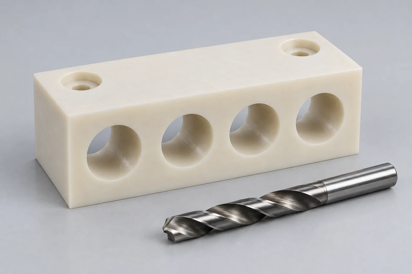
For procurement teams, the useful question is whether the delivered hole will accept the intended fastener, locate the component or carry the required flow under specified conditions. A drill size is a manufacturing input. A finished hole requirement describes the result you need to buy.
Start With The Function Of Each Hole
Separate clearance holes from locating bores, threaded pilot holes and fluid passages. They may have similar appearances but require different acceptance criteria. A screw clearance hole can work over a practical size range, while a locating bore may need a controlled relationship to another feature.
A counterbore adds another function. Its diameter and depth determine whether a screw head or washer seats correctly. Also consider the remaining material beneath it. Increasing the counterbore depth to hide hardware can change the support available to carry the clamping load.
For a passage in a manifold, identify the connection points and any intersecting holes. State whether the design requires a particular internal edge condition or cleanliness level. Do not assume that a clean external opening proves the entire passage is free of loose material.
Give every important hole an identifiable drawing callout. That lets the quotation, first article report and receiving inspection refer to the same feature. It also prevents a supplier from applying an expensive locating requirement to holes that only provide generous fastener clearance.
Specify Diameter, Depth And Position Separately
Hole diameter does not define hole location. Position must relate to functional datums, such as a mounting face and two locating features. Choose those references from the assembly rather than whichever outer surfaces are easiest to measure on the loose component.
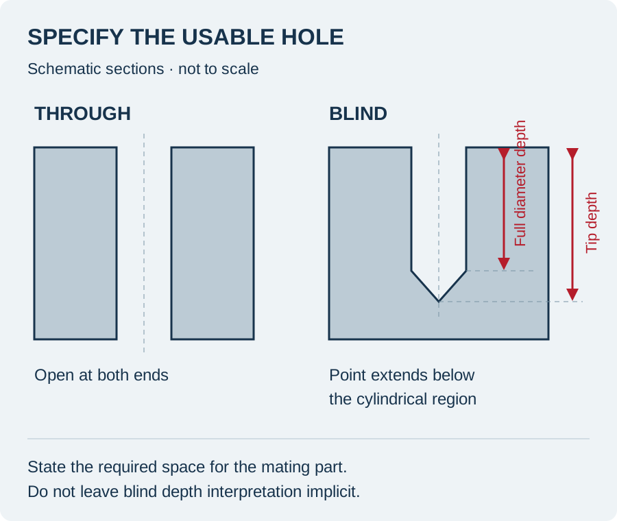
For a blind hole, distinguish usable full diameter depth from the depth reached by the drill point. A pointed tool can extend beyond the cylindrical portion of the hole. If a pin must enter to a defined distance, the drawing should describe the usable space required for that pin.
For a threaded blind hole, separate full thread engagement from drill depth as well. The tool needs room that does not necessarily become usable thread. Leave the process allowance for supplier review while clearly specifying the engagement the assembly actually requires.
| Hole function | Drawing information to define | Acceptance question |
|---|---|---|
| Fastener clearance | Diameter range, location and entry edge | Does the intended fastener pass freely? |
| Locating bore | Size, datum relationship and relevant form | Does the mating feature locate without binding? |
| Counterbored mounting | Head recess size, depth and seating surface | Does the hardware seat without interference? |
| Blind pin hole | Full diameter depth and bottom restrictions | Can the pin reach its intended position? |
| Internal passage | Connections, intersections and cleanliness | Is the intended route open and acceptably clean? |
Use consistent units and identify which document controls when a model and drawing disagree. A model can describe nominal geometry well, but inspection requirements and permissible edge changes still need clear communication.
Why Heat And Chip Removal Matter
Plastics do not respond to a drilling operation exactly like metal. Heat, rubbing and trapped chips can affect the developing bore. The MCG guide to machining plastic parts highlights heat accumulation during drilling and recommends attention to chip evacuation, including periodic tool withdrawal. Its recommendations are starting points for process development, not a guarantee for every geometry.
A deep passage gives chips a longer route out. A blind bottom and a breakthrough into another bore create different cutting conditions. Review those transitions when quoting rather than discovering the difficult section only after the rest of the component has been machined.
Ask the supplier how the proposed process will control heat and remove chips for the selected grade. The answer may involve tool geometry, a staged operation or a suitable cooling approach. Avoid prescribing one fixed speed and feed for all polymers and hole sizes.
If a passage is functionally important, define how its condition will be verified. A dimension taken at the entrance alone cannot establish the size, straightness or cleanliness throughout its length. The inspection method needs access to the area that actually matters.
Cooling Must Be Compatible With The Material
Dry machining is not automatically the right choice, and liquid cooling is not automatically harmless. Ensinger's machining FAQ identifies deep drilling as a situation that can require cooling and discusses material compatibility, including stress cracking concerns for susceptible plastics. Review both heat control and the effect of the medium.
Tell the supplier if the part has restrictions on processing residues. Include any approved cleaning method or prohibited substances where relevant. A machining fluid that suits the cutting operation may still create additional cleaning or qualification work for the finished application.
For transparent components, assess appearance requirements alongside dimensions. Specify which faces and bore surfaces are functional viewing areas, and which are simply clearance features. Avoid a vague instruction for every surface to be optically clear if only a small viewing region matters.
Keep chemical exposure during manufacturing separate from exposure during service. Both need review, but they answer different questions. The existing guide to chemical resistance of plastics can help organize the operating environment information supplied with an RFQ.
Support The Part Without Distorting It
A thin plate, a flexible block and a thick sleeve need different support arrangements. Ask the shop to consider how the component sits during drilling and how it behaves after release. A measurement made while a plate is heavily restrained may not describe its free condition.
Through holes introduce an exit edge. Where the design permits, support near the exit can be part of the manufacturing plan. Where there is no backing access, the supplier may need a different operation or sequence. The drawing should define the acceptable finished edge rather than assume a particular fixture.
Review hole spacing and nearby walls. Several closely spaced bores can leave narrow sections that deserve extra attention during clamping, machining and handling. Do not infer a safe minimum wall from one unrelated material or component. Evaluate the actual grade and loading arrangement.
For parts with extensive material removal, discuss when critical holes will be finished relative to the surrounding pockets and faces. The plastic machining warpage guide explains why the completed geometry and process sequence need to be considered together.
Drilling, Boring And Reaming Serve Different Needs
Drilling creates the initial hole. A later operation may be selected to control the finished size, form, location or surface more closely. Boring and reaming are possible finishing routes, but their suitability depends on the access, material and feature requirements.
Do not assume that every hole needs an additional finishing operation. A practical clearance hole may be acceptable directly from a suitable drilling process. Conversely, calling a tight bore drilled does not establish that the proposed route can achieve the required final condition.
Discuss the result before locking the manufacturing method. State the functional tolerance and inspection requirement, then let the supplier explain the route. If a process itself is mandatory for a qualified design, make that restriction explicit and explain how changes will be approved.
For a sleeve or roller with a central bore, evaluate the relationship between the internal and external features. Machining them in coordinated setups may matter more than choosing a nominally finer size tolerance alone. Our CNC plastic turning service is a relevant starting point for rotational components.
Inspect The Finished Hole In A Defined State
A plug gauge can answer a functional size question, but it does not independently establish position or every form characteristic. Agree what the chosen gauge proves and what needs another method. Excessive insertion force can also obscure whether the free component meets the intended requirement.
An illustrative inspection setup places a drilled plate beside plug gauges and a support block. The key decision is how the actual component will be supported and measured. The illustration is not a calibration record or evidence of a production inspection result.
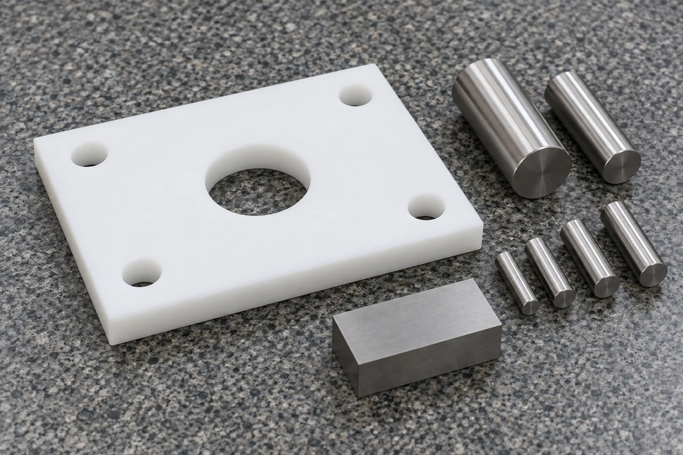
Define the measurement state for critical bores. Include relevant temperature or conditioning requirements and whether the component is free, lightly supported or installed. Avoid comparing readings taken under different conditions as if they describe the same acceptance test.
For depth, use an approach that distinguishes the usable cylindrical region from the pointed bottom. For location, identify the datum setup and feature evaluation. For long holes, decide whether additional access or section specific measurements are necessary to support the requirement.
Record the instrument, feature identifier and result in the agreed report. If a fit is critical, a representative mating component can complement dimensional inspection. It should not silently replace the drawing criteria unless the parties have explicitly agreed that acceptance method.
Example: A Manifold With Intersecting Passages
Consider a hypothetical machined plastic manifold with mounting holes and intersecting internal passages. The original drawing gives outside dimensions and bore diameters but says little about intersection condition. A buyer could receive dimensionally plausible parts that still require substantial clarification before assembly.
First, separate the mounting functions from the flow path. Assign datums that match the installation. Identify which blind ends are permitted and which openings must communicate. Mark any features reserved for plugs, inserts or another specified connection system.
Next, agree how intersections will be checked and cleaned. A process that removes an external burr may not reach an internal crossing. The supplier should review accessibility before committing to the route, and the customer should state any cleanliness acceptance requirement.
Finally, define first article evidence. It might include a dimensional report, an agreed passage inspection and an application specific functional check. Pressure or leak acceptance must be separately defined by the responsible party; it cannot be inferred from bore dimensions alone.
This example describes a review method, not a customer case or a claimed qualification. For a real project, provide the relevant connection details with your plastic manifold inquiry so unresolved requirements can be addressed before production.
Resolve Common Quotation Differences
Two quotations may price different interpretations of the same hole note. One may include additional bore finishing, internal inspection and cleaning, while another covers nominal drilling only. Compare the proposed scope before concluding that the difference is simply machining cost.
Identify the few dimensions that control assembly. A uniform tight tolerance on every hole can create unnecessary manufacturing and inspection work. On the other hand, removing a locating requirement merely to reduce cost can transfer the problem to assembly.
State whether alternative grades or stock forms are allowed. A familiar polymer abbreviation is not enough to approve every formulation. Keep the approved material connected to the drawing revision and any trial evidence, especially for repeat orders with fitted bores.
RFQ Checklist For Drilled Plastic Components
Send the drawing and model together with quantity, part number and destination country. Identify material grade, hole functions and critical datums. Include mating hardware information when the hole has a locating, fastening or connection role that cannot be understood from geometry alone.
Specify usable blind depths, thread engagement where applicable, permitted entry and exit edge changes, and relevant internal cleanliness requirements. State the inspection condition and reporting scope. If these are still undecided, ask for a drawing review rather than letting the quotation imply agreement.
For repeat components, share relevant first article findings and describe what has changed. A new hole depth, material grade or mounting arrangement can alter the review even when the part name remains the same. Preserve those changes in a controlled revision rather than an informal note on an old purchase order.
Frequently Asked Questions
Is Drill Diameter The Same As Finished Hole Diameter?
Not necessarily. The drawing should specify the required finished hole. Tool size is one input to the process, and the result must be checked in the agreed state. Do not replace inspection evidence with the nominal marking on the drill.
Should Every Plastic Hole Be Reamed?
No. Decide from the feature's function and acceptance requirements. Some clearance holes need no separate finishing operation. A critical bore may need a different route, but reaming should be justified against the material, access and desired result.
How Should A Blind Hole Depth Be Specified?
State the usable full diameter depth and any bottom restrictions. For threaded holes, also identify required engagement. Clarify whether an existing depth note refers to the drill tip or cylindrical region before the component is manufactured.
Can A Through Hole Be Drilled From Both Ends?
It may be an option, but the meeting region needs review. Agree the permissible alignment and internal step condition. A passage that looks acceptable from each entrance can still fail a functional requirement where the operations meet.
Does A Smooth Entrance Prove The Bore Is Acceptable?
No. The controlling region may be deeper inside or at an intersection. Match the inspection method to the required size, form, position and cleanliness. External appearance is useful evidence only for the surfaces it actually reveals.
Do Hole Dimensions Establish A Manifold Pressure Rating?
No. Pressure suitability depends on the complete design, material, connections and defined validation conditions. Specify any required pressure or leak evaluation separately. A machining drawing alone should not be treated as evidence of an approved service rating.
Request A Drawing Review
Send TOPS Plastics your drawing and application details through the contact page. Mark critical holes, datums and usable depths, and include quantity and material grade. A focused review can clarify the machining and inspection scope before you commit to a batch of custom plastic components.