
Plastic gear design starts with the complete operating mesh, not a copied metal gear drawing. You need compatible tooth geometry, a defined material grade, adequate running clearance and measurable acceptance criteria. This guide explains what you should specify before requesting custom machined gears.
Define The Duty Before Choosing A Plastic Gear
Your torque cycle, operating environment and required positioning behavior determine whether a plastic gear deserves further evaluation.
Start with the driven machine rather than the gear outside diameter. Record normal torque, startup demand, occasional overloads and reversals. Include operating speed, daily running time and expected maintenance intervals. A slowly indexing mechanism differs from a continuously running drive, even when both share nominal torque.
Identify how failure affects your equipment. A replaceable feeder gear and a safety-related motion system require different validation. State whether tooth wear, angular play, contamination or sudden tooth fracture creates the limiting condition. You cannot select an appropriate inspection plan without defining that condition.
Describe the surrounding assembly too. Shaft support, housing stiffness, alignment and the mating gear influence tooth contact. Include enclosure temperature, cleaning exposure, moisture and lubricant restrictions. Ambient air temperature alone does not describe conditions at loaded tooth surfaces.
For replacements, provide the original drawing and operating history where available. A worn sample can help establish interfaces. However, wear may conceal the original tooth thickness and bore size. Ask your design owner to approve reconstructed dimensions before manufacturing.
Screen Materials By Grade And Environment
You should compare documented stock-shape grades against the application before selecting a polymer family.
POM, nylon and PEEK are possible screening candidates, rather than interchangeable answers. Your selection must address stiffness, fatigue behavior, wear, dimensional changes and available gear-specific evidence. Color and resin family alone do not identify a purchaseable material specification.
| Candidate | Why You Might Evaluate It | What You Must Resolve |
|---|---|---|
| Acetal, Or POM | Machinability and dimensional stability for precision components | Grade identity, temperature exposure and chemical compatibility |
| Nylon, Or PA | Toughness and wear-related applications | Moisture condition, dimensional movement and installed clearance |
| PEEK | Applications needing a higher-temperature material screen | Exact grade, mating surface and economic justification |
| Modified Or Reinforced Grades | A specific property requirement beyond the base polymer | Directionality, abrasive effects and relevant performance evidence |
Use the stock-shape manufacturer's documentation rather than transferring injection-molding data without review. Manufacturing route, additives and conditioning can change the properties you actually receive. Ensinger's material selection guidance provides a starting framework for comparing documented properties and application conditions.
Treat published tensile values as screening information, not a completed gear rating. Repeated tooth loading, operating temperature and contact behavior require their own evaluation. A higher material price does not demonstrate longer service life in your mechanism.
For nylon, specify the condition associated with dimensions and acceptance. Moisture exposure can change properties and dimensions. Ensinger's machinable-plastics FAQ explains this conditioning behavior. Use grade-specific information when establishing storage and assembly requirements.
Specify The Tooth System Completely
A gear drawing must define the tooth system and its relationship to the bore and mounting faces.
Outside diameter and tooth count are insufficient for a reliable replacement. State module or diametral pitch, pressure angle, tooth count and face width. Include helix angle and handedness where applicable. Identify profile modifications, tooth thickness requirements and the applicable drawing convention.
Provide the mating gear details and nominal shaft center distance. Two gears can appear compatible while producing incorrect contact or interference. Confirm that the tooth systems agree before reviewing material or manufacturing cost.
Choose functional datums that represent installation. The bore axis often establishes rotation, while a mounting face establishes axial location. Define how the tooth geometry relates to those datums. A good outside diameter does not prove concentric tooth engagement.
Specify tooth quality through an agreed standard and measurement method when your application needs it. Do not use an unexplained metal-gear accuracy callout as a substitute for discussion. The supplier must confirm feasibility, measurement access and the material condition associated with acceptance.
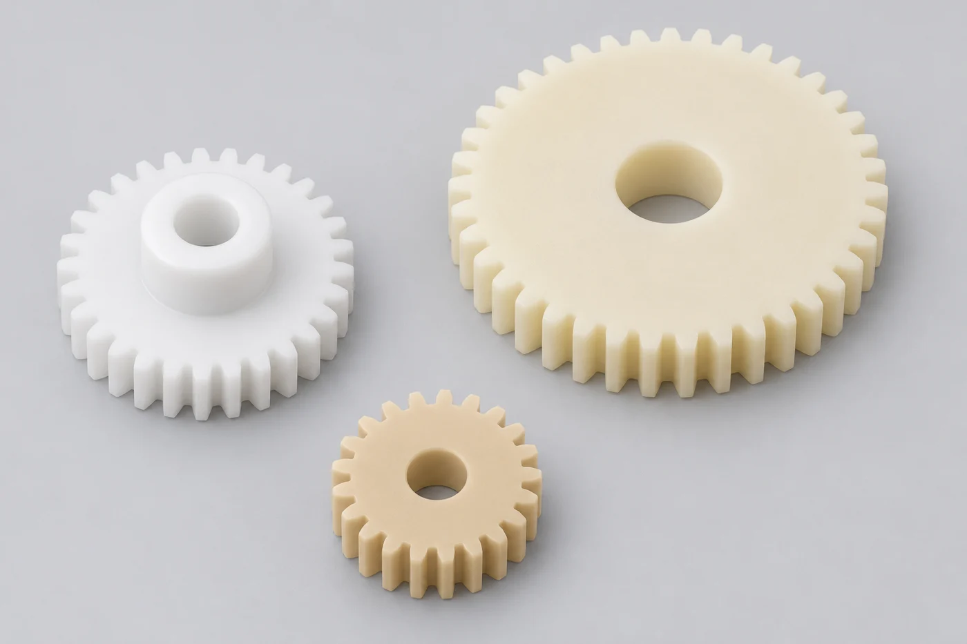
The product illustrations show conceptual gears rather than rated assemblies. They explain geometry and review points without establishing tooth accuracy, capacity or service life.
Design Backlash For The Operating Mesh
Backlash must accommodate the actual operating assembly while remaining compatible with your positioning requirement.
Backlash describes clearance between mating tooth flanks. It is different from shaft-bearing clearance, bore fit and axial endplay. Those movements can combine in measured output play, but they require separate controls and remedies.
Build the clearance review around assembly conditions. Include tooth thickness variation, shaft center distance, runout, alignment, temperature and material conditioning. Evaluate plausible combinations rather than checking only nominal dimensions. Avoid assuming that every dimensional change acts independently.
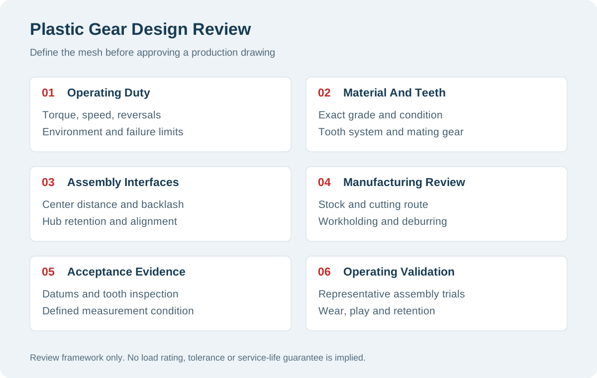
Thermal expansion affects the polymer gears and their supporting structure differently. Moisture can introduce another dimensional change in susceptible grades. Neither effect justifies a universal backlash percentage. Calculate an application-specific range, then validate representative assemblies across the intended environment.
Use the plastic thermal expansion guide when defining temperature states for the drawing. Record whether the accepted mesh is dry, conditioned, cold, stabilized or running. Otherwise, different teams may measure different conditions and report conflicting results.
Do not remove all clearance simply to reduce positional error. Binding and higher operating resistance can create another failure mode. Where reversal accuracy dominates, review the complete drive architecture with your design engineer before committing to plastic gears.
Review The Hub And Shaft Connection
Your hub must transmit torque without relying on unsupported assumptions about polymer clamping or long-term interference.
Check the entire load path from shaft to hub and into the tooth rim. A narrow hub, sharp keyway or thin section can become critical before the teeth. Specify generous transitions where geometry permits, while retaining necessary assembly clearance.
Compare keyed, clamped, inserted and interference-based connections through a design review. Each arrangement changes local stress, assembly forces and serviceability. Metal inserts also introduce differential movement and an additional interface. Their presence does not automatically solve torque transfer.
The assembly illustration separates the gear, shaft and sleeve to clarify these interfaces. It does not prescribe a particular attachment method or represent a validated connection.
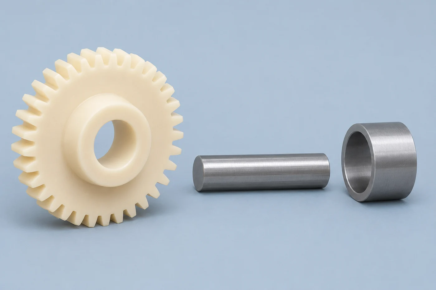
If you propose an interference fit, define assembly temperature, shaft finish, hub wall thickness and retention expectations. Consider stress relaxation and environmental changes. Review the press-fit design guide before assuming an initial fit remains unchanged throughout service.
Avoid tightening a fastener until the gear stops moving as your assembly specification. Define the intended retention arrangement and any approved assembly procedure. Record whether maintenance permits removal, repeated installation or replacement of only the polymer element.
Agree On A Practical Manufacturing Route
Your manufacturing plan should preserve functional relationships while controlling heat, workholding distortion and damage to finished teeth.
A machined gear may require turning, tooth generation, milling and secondary operations. Confirm the actual tooth-cutting route with the supplier. General CNC machining capability alone does not establish availability of every gear geometry or accuracy class.
Use this review sequence before releasing a production order:
- Freeze the tooth definition, material grade, datums and operating requirements.
- Confirm stock availability, documentation and any conditioning requirements.
- Agree on blank preparation, bore creation and tooth-generation feasibility.
- Identify workholding surfaces and protect thin rims from excessive deformation.
- Define deburring methods that preserve functional tooth surfaces and root geometry.
- Inspect the first article before approving repeat production.
Review planned holding surfaces during DFM. A finished tooth flank should not become a casual gripping surface. Consider how releasing the workpiece could change measured bore alignment or face position.
The Mitsubishi Chemical machining toolkit discusses tooling, cooling and dimensional considerations for engineering plastics. Apply its material-processing guidance alongside a separate gear-specific manufacturing and inspection plan. It does not establish TOPS equipment or a universal gear tolerance.
Inspect Geometry And Functional Engagement
Your inspection plan should separate individual gear geometry from behavior in the assembled mesh.
Start with traceable identification, drawing revision and material documentation. Record dimensions in the agreed environmental condition. Inspect the bore, mounting faces, tooth-related features and damage risks against specified acceptance criteria.
| Inspection Question | Evidence To Agree Before Ordering |
|---|---|
| Does The Gear Mount Correctly? | Bore dimensions, mounting-face requirements and functional datums |
| Are Teeth Acceptable? | Agreed tooth measurement, inspection coverage and reporting method |
| Does Rotation Remain Consistent? | Specified runout checks relative to the installation axis |
| Does The Pair Engage Correctly? | Defined mating gear, center distance and mesh-check procedure |
| Can Results Be Compared? | Temperature, conditioning state, fixture and measurement-force controls |
A rolling or functional mesh check can reveal assembled behavior. However, it does not identify every individual geometric error. Likewise, a dimensional report cannot independently demonstrate acceptable wear or endurance. Choose evidence according to the failure mode you need to control.
Specify acceptable burrs, edge damage and surface defects in functional terms. Rounded tooth tips do not prove that the roots and flanks remain correct. Where visual judgment matters, agree on reference samples or clearly documented acceptance examples.
Validate The Gear Before Scaling Production
Representative operating trials are necessary when drawings and material data cannot establish acceptable performance alone.
Define a test plan before making prototypes. State loads, speeds, reversals, environment, lubrication and mating components. Include startup conditions and credible abnormal events. Set measurable stopping criteria rather than waiting for obvious tooth breakage.
Track backlash change, wear, temperature and any noise or vibration relevant to your machine. Inspect the hub connection separately from the tooth surfaces. Identify whether a problem originates in material choice, alignment, tooth geometry or mounting.
Keep the prototype route representative of the proposed production route where practical. A machined prototype and a molded production gear may require separate validation. Changing material grade or manufacturing method after approval can invalidate earlier assumptions.
Avoid plastic gears where the required evidence remains unavailable for a consequential failure mode. Consider metal, another drive arrangement or specialist gear engineering support. Your decision should reflect demonstrated system behavior, rather than an assumption that polymer always reduces noise or maintenance.
Separate Mesh Problems From Mounting Problems
Check the failure pattern before changing material. Uneven contact across the face suggests a different investigation from uniform flank wear. Inspect shaft alignment, support movement and assembly position before blaming the polymer grade.
Document your observations with part identification and operating conditions. Record when the behavior appeared, whether it follows reversal and whether temperature changes it. These details help your engineering team choose a focused corrective trial.
Change one controlled variable at a time where practical. Replacing the grade, hub arrangement and center distance together obscures the reason for improvement. Preserve approved samples and inspection records so later batches remain comparable.
Control Purchasing Scope And Cost
You reduce quotation uncertainty by separating functional requirements from preferences and documenting the required evidence.
Material grade, blank size, tooth geometry, quantity and inspection affect cost. A complicated hub or uncommon tooth form can add manufacturing difficulty. Documentation, conditioning and validation requirements also belong in the commercial scope.
Compare quotations against the same drawing revision and acceptance plan. Ask which operations, reports and material records are included. A cheaper offer may exclude the tooth inspection or functional review that your application requires.
TOPS presents custom gear sourcing and drawing review through its plastic gears page. Use that page to start a project discussion. Confirm the proposed geometry, manufacturing route and inspection scope before interpreting the quotation as technical approval.
Plastic Gear Design FAQ
These answers address common specification questions before you order custom machined plastic gears.
Is POM Always Better Than Nylon For Gears?
No. Compare the exact grades against moisture exposure, loading, temperature and dimensional requirements. Validate the intended mating pair.
Can You Copy A Metal Gear In Plastic?
You can evaluate the geometry, but material substitution requires a fresh design review. Recheck stiffness, clearance, mounting and performance evidence.
How Much Backlash Should You Specify?
There is no universal value. Establish an operating range using tooth geometry, assembly variation, environment and required positioning behavior.
Can A Worn Gear Serve As The Only Drawing?
It can support reconstruction, but wear can hide original dimensions. Obtain design approval for the reconstructed tooth system and interfaces.
Do Plastic Gears Always Run Without Lubrication?
No. Dry-running suitability depends on grade, mating surface and operating conditions. Confirm the intended arrangement through relevant evidence and trials.
Does A Metal Hub Guarantee Reliable Torque Transfer?
No. Review the polymer-to-metal interface, retention method and environmental movement. The complete connection still requires validation.
Is A Standard Dimensional Report Enough?
Only when it covers your agreed acceptance requirements. Tooth geometry, functional engagement and endurance may require separate evidence.
What Should You Send For A Quote?
Provide the drawing, CAD model, grade, quantities, mating gear information and operating conditions. Include inspection expectations and required delivery documentation.
Request A Drawing Review
A useful plastic gear specification connects the tooth system, operating mesh, hub design and acceptance evidence. Send your drawing, material grade, mating details, quantities and validation requirements. Contact us to confirm feasibility and quotation scope before ordering.